最近一直都比较忙,做了一些东西但是没有时间更新博客,这次写个小玩物,也可以说是一个实验,实现效果不错,很适合初学者自己动手做一个。
首先先上实物图
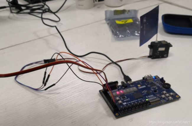
实验平台:EGO1开发板
FPGA型号:xc7a35tcsg324-1
代码平台:VIVADO
实现功能:按键数码管计数,0-99,麦克风控制舵机旋转,舵机旋转为顺时针180°后迅速转回,每次麦克风收到声音后,舵机会在转与不转中来回切换,流水灯在流与不流之间切换。
下面我们看RTL图
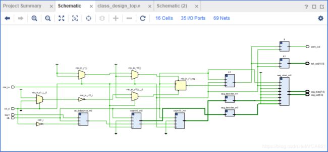
1.顶层文件
`timescale 1ns/1ps
module class_design_top(
                          input         clk,
                          input         mic_in,
                          input         rst_n,
                          input         key1,
                          output [5:0]  seg_sel,
                          output [7:0]  seg_data,
                          output        pwm_out,
                          output [15:0] led_out
                          );
wire      clk_en;
reg       mic_in_r1 = 1'b1;

always @ (posedge clk or negedge rst_n)
begin
    if(!rst_n)
    mic_in_r1 = 1'b1;
    else
    mic_in_r1 <= mic_in;
end

pwm_out li(
            .clk(clk_en),
            .rst_n(rst_n),
            .pwm_out(pwm_out)
           );
mic_switch li1(
                 .clk(clk),
                 .rst_n(rst_n),
                 .sound_in(mic_in_r1),
                 .clk_en(clk_en)
               );
flowing_light li2(
                 .clk(clk_en),
                 .rst(rst_n),
                 .led(led_out)
               );


wire button_posedge;
ax_debounce ax_debounce_m0
(
    .clk             (clk),
    .rst             (~rst_n),
    .button_in       (key1),
    .button_posedge  (button_posedge),
    .button_negedge  (),
    .button_out      ()
);

wire[3:0] count;
wire t0;
count_m10 count10_m0(
    .clk    (clk),
    .rst_n  (rst_n),
    .en     (button_posedge),
    .clr    (1'b0),
    .data   (count),
    .t      (t0)
);
wire[3:0] count1;
wire t1;
count_m10 count10_m1(
    .clk    (clk),
    .rst_n  (rst_n),
    .en     (t0),
    .clr    (1'b0),
    .data   (count1),
    .t      (t1)
);
wire[6:0] seg_data_0;
seg_decoder seg_decoder_m0(
    .bin_data  (count),
    .seg_data  (seg_data_0)
);

wire[6:0] seg_data_1;
seg_decoder seg_decoder_m1(
    .bin_data  (count1),
    .seg_data  (seg_data_1)
);
seg_scan seg_scan_m0(
    .clk        (clk),
    .rst_n      (rst_n),
    .seg_sel    (seg_sel),
    .seg_data   (seg_data),
    .seg_data_0 ({1'b1,7'b1111_111}),
    .seg_data_1 ({1'b1,7'b1111_111}),
    .seg_data_2 ({1'b1,7'b1111_111}),
    .seg_data_3 ({1'b1,7'b1111_111}),
    .seg_data_4 ({1'b1,seg_data_1}),
    .seg_data_5 ({1'b1,seg_data_0})
);

endmodule
2.pwm产生文件,此代码为舵机的控制代码,对舵机控制有问题的同学请自行查询资料。
module pwm_out(
                 input         clk,
                 input         rst_n,

                 output        pwm_out
                 );

reg  [20:0]   cnt = 21'd0;
reg  [17:0]   duty_cnt = 18'd100_000;
reg           pwm_out_r1 = 1'b0;
reg           flag = 1'b0;

assign pwm_out = pwm_out_r1;

always@(posedge clk or negedge rst_n)
begin
    if(!rst_n)
    cnt <= 21'd0;
    else if(cnt == 21'd1_000_000)
    begin
    cnt <= 21'd0;
    pwm_out_r1 <= 1'b1;
    end
    else if(cnt == duty_cnt)
    begin
    pwm_out_r1 <= 1'b0;
    cnt <= cnt + 21'd1;
    end
    else
    cnt <= cnt + 21'd1;
end

always @ (posedge clk or negedge rst_n)
begin
    if(!rst_n)
    duty_cnt <= 18'd50_000;
    else if(cnt == 21'd1_000_000)
    begin
    if (duty_cnt == 18'd100_000)
    duty_cnt <= 18'd50_000;
    else
    duty_cnt <= duty_cnt + 18'd250;
    end

end
3.麦克风开关函数,控制舵机的状态,该地方不能直接通过模块控制,因为麦克风模块收到声音后,并不是回输出一段高电平,而是很多20ms左右的杂乱的方波,对于高速率的FPGA来说,无法作为一个稳定的触发,所以本设计巧妙的将麦克风模块的信号接入80ms技术器的复位端,当声音输入,杂乱的方波会一直复位计数器,当最后一个下降沿后80ms,择可判断一次声音结束,这样的判断方法精度很高,实测效果很好。(差点就去给模块加滤波电路了)控制舵机和流水灯的方式为是否提供时钟
module pwm_out(
                 input         clk,
                 input         rst_n,

                 output        pwm_out
                 );

reg  [20:0]   cnt = 21'd0;
reg  [17:0]   duty_cnt = 18'd100_000;
reg           pwm_out_r1 = 1'b0;
reg           flag = 1'b0;

assign pwm_out = pwm_out_r1;

always@(posedge clk or negedge rst_n)
begin
    if(!rst_n)
    cnt <= 21'd0;
    else if(cnt == 21'd1_000_000)
    begin
    cnt <= 21'd0;
    pwm_out_r1 <= 1'b1;
    end
    else if(cnt == duty_cnt)
    begin
    pwm_out_r1 <= 1'b0;
    cnt <= cnt + 21'd1;
    end
    else
    cnt <= cnt + 21'd1;
end

always @ (posedge clk or negedge rst_n)
begin
    if(!rst_n)
    duty_cnt <= 18'd50_000;
    else if(cnt == 21'd1_000_000)
    begin
    if (duty_cnt == 18'd100_000)
    duty_cnt <= 18'd50_000;
    else
    duty_cnt <= duty_cnt + 18'd250;
    end

end
4.流水灯代码
`timescale 1ns / 1ps


module flowing_light(
       input clk,
       input rst,
       output [15:0] led
);


     reg [23 : 0] cnt_reg;
     reg [15 : 0] light_reg;


     always @ (posedge clk)
          begin
               if (!rst)
               cnt_reg <= 0;
               else
               cnt_reg <= cnt_reg + 1;
          end


     always @ (posedge clk)
          begin
               if (!rst)
               light_reg <= 16'h0001;
               else if (cnt_reg == 24'hffffff)
               begin
                    if (light_reg == 16'h8000)
                        light_reg <= 16'h0001;
               else
                    light_reg <= light_reg << 1;
               end
          end
assign led = light_reg;
endmodule
5.经典的按键消抖和防止亚稳态的代码,来自黑金
`timescale 1 ns / 100 ps
module  ax_debounce
(
    input       clk,
    input       rst,
    input       button_in,
    output reg  button_posedge,
    output reg  button_negedge,
    output reg  button_out
);
//// ---------------- internal constants --------------
parameter N = 32 ;           // debounce timer bitwidth
parameter FREQ = 100;         //model clock :Mhz
parameter MAX_TIME = 20;     //ms
localparam TIMER_MAX_VAL =   MAX_TIME * 1000 * FREQ;
////---------------- internal variables ---------------
reg  [N-1 : 0]  q_reg;      // timing regs
reg  [N-1 : 0]  q_next;
reg DFF1, DFF2;             // input flip-flops
wire q_add;                 // control flags
wire q_reset;
reg button_out_d0;
//// ------------------------------------------------------

////contenious assignment for counter control
assign q_reset = (DFF1  ^ DFF2);          // xor input flip flops to look for level chage to reset counter
assign q_add = ~(q_reg == TIMER_MAX_VAL); // add to counter when q_reg msb is equal to 0

//// combo counter to manage q_next
always @ ( q_reset, q_add, q_reg)
begin
    case( {q_reset , q_add})
        2'b00 :
                q_next <= q_reg;
        2'b01 :
                q_next <= q_reg + 1;
        default :
                q_next <= { N {1'b0} };
    endcase
end

//// Flip flop inputs and q_reg update
always @ ( posedge clk or posedge rst)
begin
    if(rst == 1'b1)
    begin
        DFF1 <= 1'b0;
        DFF2 <= 1'b0;
        q_reg <= { N {1'b0} };
    end
    else
    begin
        DFF1 <= button_in;
        DFF2 <= DFF1;
        q_reg <= q_next;
    end
end

//// counter control
always @ ( posedge clk or posedge rst)
begin
	if(rst == 1'b1)
		button_out <= 1'b1;
    else if(q_reg == TIMER_MAX_VAL)
        button_out <= DFF2;
    else
        button_out <= button_out;
end

always @ ( posedge clk or posedge rst)
begin
	if(rst == 1'b1)
	begin
		button_out_d0 <= 1'b1;
		button_posedge <= 1'b0;
		button_negedge <= 1'b0;
	end
	else
	begin
		button_out_d0 <= button_out;
		button_posedge <= ~button_out_d0 & button_out;
		button_negedge <= button_out_d0 & ~button_out;
	end
end
endmodule
6.两个模10计数器代码,主要是对数码管计数控制
module count_m10(
                 input          clk,
                 input          rst_n,
                 input          en,    //Counter enable
                 input          clr,   //Counter synchronous reset
                 output reg[3:0]data,  //counter value
                 output reg     t      // carry enable signal
                );
always@(posedge clk or negedge rst_n)
begin
    if(rst_n==0)
    begin
        data <= 4'd0;
        t <= 1'd0;
    end
    else if(clr)
    begin
        data <= 4'd0;
        t <= 1'd0;
    end
    else if(en)
    begin
        if(data==4'd9)
        begin
            t<= 1'b1;    //Counter to 9 to generate carry
            data <= 4'd0;//Counter to 9 reset
        end
        else
        begin
            t <= 1'b0;
            data <= data + 4'd1;
        end
    end
    else
        t <= 1'b0;
end

endmodule
7.数码管编码器
module seg_decoder
(
	input[3:0]      bin_data,     // bin data input
	output reg[6:0] seg_data      // seven segments LED output
);

always@(*)
begin
	case(bin_data)
		4'd0:seg_data <= ~(7'b100_0000);
            4'd1:seg_data <= ~(7'b111_1001);
            4'd2:seg_data <= ~(7'b010_0100);
            4'd3:seg_data <= ~(7'b011_0000);
            4'd4:seg_data <= ~(7'b001_1001);
            4'd5:seg_data <= ~(7'b001_0010);
            4'd6:seg_data <= ~(7'b000_0010);
            4'd7:seg_data <= ~(7'b111_1000);
            4'd8:seg_data <= ~(7'b000_0000);
            4'd9:seg_data <= ~(7'b001_0000);
            4'ha:seg_data <= ~(7'b000_1000);
            4'hb:seg_data <= ~(7'b000_0011);
            4'hc:seg_data <= ~(7'b100_0110);
            4'hd:seg_data <= ~(7'b010_0001);
            4'he:seg_data <= ~(7'b000_0110);
            4'hf:seg_data <= ~(7'b000_1110);
            default:seg_data <= ~(7'b111_1111);
	endcase
end
endmodule
8.数码管扫描代码
module seg_scan(
	input           clk,
	input           rst_n,
	output reg[5:0] seg_sel,      //digital led chip select
	output reg[7:0] seg_data,     //eight segment digital tube output,MSB is the decimal point
	input[7:0]      seg_data_0,
	input[7:0]      seg_data_1,
	input[7:0]      seg_data_2,
	input[7:0]      seg_data_3,
	input[7:0]      seg_data_4,
	input[7:0]      seg_data_5
);
parameter SCAN_FREQ = 400;     //scan frequency
parameter CLK_FREQ = 100000000; //clock frequency

parameter SCAN_COUNT = CLK_FREQ /(SCAN_FREQ * 6) - 1;

reg[31:0] scan_timer;  //scan time counter
reg[3:0] scan_sel;     //Scan select counter
always@(posedge clk or negedge rst_n)
begin
	if(rst_n == 1'b0)
	begin
		scan_timer <= 32'd0;
		scan_sel <= 4'd0;
	end
	else if(scan_timer >= SCAN_COUNT)
	begin
		scan_timer <= 32'd0;
		if(scan_sel == 4'd5)
			scan_sel <= 4'd0;
		else
			scan_sel <= scan_sel + 4'd1;
	end
	else
		begin
			scan_timer <= scan_timer + 32'd1;
		end
end
always@(posedge clk or negedge rst_n)
begin
	if(rst_n == 1'b0)
	begin
		seg_sel <= 6'b000000;
		seg_data <= 8'h00;
	end
	else
	begin
		case(scan_sel)
			//first digital led
			4'd0:
			begin
				seg_sel <= 6'b00_0001;
				seg_data <= seg_data_0;
			end
			//second digital led
			4'd1:
			begin
				seg_sel <= 6'b00_0010;
				seg_data <= seg_data_1;
			end
			//...
			4'd2:
			begin
				seg_sel <= 6'b00_0100;
				seg_data <= seg_data_2;
			end
			4'd3:
			begin
				seg_sel <= 6'b00_1000;
				seg_data <= seg_data_3;
			end
			4'd4:
			begin
				seg_sel <= 6'b01_0000;
				seg_data <= seg_data_4;
			end
			4'd5:
			begin
				seg_sel <= 6'b10_0000;
				seg_data <= seg_data_5;
			end
			default:
			begin
				seg_sel <= 6'b00_0000;
				seg_data <= 8'h00;
			end
		endcase
	end
end

endmodule
以上为整个工程所有代码,代码简单容易理解,所有.v文件上面都有,自己记录一下,如果有需要的同学可在下方留言,我会看的^_^!