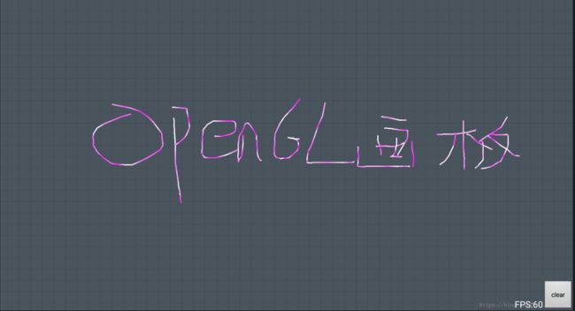
使用GLSurfaceView实现涂鸦画板功能
首先需要实现一个画线工具,代码如下:
package com.project.testOpenGLWithAndroidUI;

import android.util.Log;

import java.nio.ByteBuffer;
import java.nio.ByteOrder;
import java.nio.FloatBuffer;

import javax.microedition.khronos.opengles.GL10;

/**
 * Created by cjz on 2018/8/14.
 */

public class GLLine {
    /**顶点字节数组**/
    private ByteBuffer pointByteBuffer;
    /**顶点RGBA字节数组**/
    private ByteBuffer colorByteBuffer;
    /**顶点坐标数组**/
    private FloatBuffer pointBuffer = null;
    /**顶点RGBA数组**/
    private FloatBuffer colorBuffer = null;
    /**正在写入第几个顶点float**/
    private int pointBufferPos = 0;
    /**正在写入第几个颜色float**/
    private int colorBufferPos = 0;
    /**初始化时的顶点数目**/
    private int initVertexCount = 1 * 1024;

    public void drawLine(float x, float y) {
        //按初始化大小初始化顶点字节数组和顶点数组
        if (pointBuffer == null) {
            pointByteBuffer = ByteBuffer.allocateDirect(initVertexCount * 4);    //顶点数 * sizeof(float)
            pointByteBuffer.order(ByteOrder.nativeOrder());
            pointBuffer = pointByteBuffer.asFloatBuffer();
            pointBuffer.position(0);
            pointBufferPos = 0;
        }
        //按初始化大小初始化RGBA字节数组和RGBA数组
        if (colorBuffer == null) {
            colorByteBuffer = ByteBuffer.allocateDirect(initVertexCount * 4);
            colorByteBuffer.order(ByteOrder.nativeOrder());
            colorBuffer = colorByteBuffer.asFloatBuffer();
            colorBuffer.position(0);
            colorBufferPos = 0;
        }
        //写入坐标值x,y,z
        pointBuffer.put(pointBufferPos++, x);
        pointBuffer.put(pointBufferPos++, y);
        pointBuffer.put(pointBufferPos++, 0f);
        //写入颜色值r,g,b,a
        colorBuffer.put(colorBufferPos++, 1f);
        colorBuffer.put(colorBufferPos++, (float) Math.random());
        colorBuffer.put(colorBufferPos++, 1f);
        colorBuffer.put(colorBufferPos++, 1f);
        //如果写入的颜色数超过初始值,将顶点数和颜色数组容量翻倍
        if (colorBufferPos * 4 >= initVertexCount) {
            Log.i("GLLines", "扩容点数到:" + initVertexCount);
            initVertexCount *= 2;

            ByteBuffer qbb = ByteBuffer.allocateDirect(initVertexCount * 4);    //顶点数 * sizeof(float) ;
            qbb.order(ByteOrder.nativeOrder());
            System.arraycopy(pointByteBuffer.array(), 0, qbb.array(), 0, (pointBufferPos) * 4);   //顶点数 * sizeof(float)
            pointByteBuffer = qbb;
            pointBuffer = pointByteBuffer.asFloatBuffer();

            ByteBuffer qbb2 = ByteBuffer.allocateDirect(initVertexCount * 4);    //顶点数 * sizeof(float) ;
            qbb2.order(ByteOrder.nativeOrder());
            System.arraycopy(colorByteBuffer.array(), 0, qbb2.array(), 0, (colorBufferPos ) * 4);  //sizeof(R,G,B,Alpha) * sizeof(float)
            colorByteBuffer = qbb2;
            colorBuffer = colorByteBuffer.asFloatBuffer();

        }
    }

    public int getVertexCount(){
        return pointBufferPos / 3;
    }

    public void drawTo(GL10 gl) {
        if (pointBuffer != null && colorBuffer != null) {
            pointBuffer.position(0);
            colorBuffer.position(0);
            gl.glVertexPointer(3, GL10.GL_FLOAT, 0, pointBuffer);
            gl.glColorPointer(4, GL10.GL_FLOAT,0, colorBuffer);
            gl.glLineWidth(3f);
            gl.glDrawArrays(GL10.GL_LINE_STRIP,0, pointBufferPos / 3); //添加的point浮点数/3才是坐标数(因为一个坐标由x,y,z3个float构成,不能直接用), 第三个参数count如果超过实际点数就会不断有指向0的点在最后
//            gl.glDrawElements(GL10.GL_LINE_STRIP,0, pointBufferPos / 3, null);  //第一个参数是点的类型,第二个参数是点的个数,第三个是第四个参数的类型,第四个参数是点的存储绘制顺序。
        }
    }
}
其中drawLine函数可以根据传来的浮点值写入到NativeBuffer中,如果线太长就会自动通过System.arraycopy扩容。drawTo是传入gl上下文之后把数组里面的顶点和顶点颜色绘制到OpenGL画布上的。(在里面我留了一个彩蛋,绿色浓度(0f~1f)我用了随机数进行赋值,使得线条呈现出紫色和白色交替的特殊效果,这也是Canvas+path难以实现的一点)
然后是渲染器:
package com.project.testOpenGLWithAndroidUI;


import android.content.Context;
import android.opengl.GLSurfaceView.Renderer;
import android.util.Log;
import android.view.MotionEvent;

import java.util.ArrayList;
import java.util.List;

import javax.microedition.khronos.egl.EGLConfig;
import javax.microedition.khronos.opengles.GL10;


public class MyGLRenderer implements Renderer {
    Context context; // Application's context
    private float x;
    private float y;

    private GLLine currentLines = null;  //当前绘制的线
    private List linesList = new ArrayList<>(); //当前绘制线的表

    public long frameCount = 0;  //共绘制了多少帧
    private float ratio;
    private int width;
    private int height;

    public MyGLRenderer(final Context context) {
        this.context = context;
    }

    /**图形引擎回调产生绘图过程,每画完一帧又会调用这个函数画下一帧**/
    @Override
    public void onDrawFrame(GL10 gl) {
        // 清除屏幕和深度缓存
        gl.glClear(GL10.GL_COLOR_BUFFER_BIT | GL10.GL_DEPTH_BUFFER_BIT);   //不加这个可以产生残影(模拟器可以)
        // 重置当前的模型观察矩阵
        gl.glLoadIdentity();

        // 允许设置顶点
        //GL10.GL_VERTEX_ARRAY顶点数组
        gl.glEnableClientState(GL10.GL_VERTEX_ARRAY);
        // 允许设置颜色
        //GL10.GL_COLOR_ARRAY颜色数组
        gl.glEnableClientState(GL10.GL_COLOR_ARRAY);
        //反走样
        gl.glEnable(GL10.GL_BLEND);
        //线条抗锯齿
        gl.glEnable(GL10.GL_LINE_SMOOTH);

        //绘制模型
        drawModel(gl);

        // 取消颜色设置
        gl.glDisableClientState(GL10.GL_COLOR_ARRAY);
        // 取消顶点设置
        gl.glDisableClientState(GL10.GL_VERTEX_ARRAY);

        //绘制结束
        gl.glFinish();

    }

    @Override
    public void onSurfaceChanged(GL10 gl, int width, int height) {
        this.width = width;
        this.height = height;
        ratio = (float) width / height;
        // 设置OpenGL场景的大小,(0,0)表示窗口内部视口的左下角,(w,h)指定了视口的大小
        gl.glViewport(0, 0, width, height);
        // 设置投影矩阵
        gl.glMatrixMode(GL10.GL_PROJECTION);
        // 重置投影矩阵
        gl.glLoadIdentity();
        // 设置视口的大小
        gl.glFrustumf(-ratio, ratio, -1, 1, 1, 10);
        //以下两句声明,以后所有的变换都是针对模型(即我们绘制的图形)
        gl.glMatrixMode(GL10.GL_MODELVIEW);
        gl.glLoadIdentity();

    }

    @Override
    public void onSurfaceCreated(GL10 gl, EGLConfig config) {
        // 设置透明色为清屏
        gl.glClearColor(0, 0, 0, 0);
    }

    /**帧绘制**/
    public void drawModel(GL10 gl) {
        gl.glTranslatef(-2f * ratio, 2f, -2f); //必须有,z轴可以用于做缩放,按16比9来做,只要右下角象限

        synchronized (linesList) {
            for(GLLine line : linesList) {
                line.drawTo(gl);
            }
        }
        frameCount++;
    }

    public void clearAll() {
        synchronized (linesList) {
            linesList.clear();
        }
    }

    public void setPointer(MotionEvent event) {
        this.x = event.getX();
        this.y = event.getY();

        switch (event.getAction()) {
            case MotionEvent.ACTION_DOWN:
                currentLines = new GLLine();
                synchronized (linesList) {
                    linesList.add(currentLines);
                }
                break;
            case MotionEvent.ACTION_MOVE:
                Log.i("setPointer", String.format("x: %f, y: %f", x, y));
                float realtiveX = x / height * 4f;  //4个象限
                float realtiveY = -y / height * 4f;
                currentLines.drawLine(realtiveX, realtiveY);
                break;
            case MotionEvent.ACTION_UP:
                break;
        }
    }


}
onDrawFrame每16ms间隔就会被调用一次,也就是绘制一帧,然后我们真正绘制线条的地方是drawModel函数,drawModel函数绘制一个List里面保存的GLLine线条对象。setPointer里面每一次接收到down事件就会创建一个GLLine线条,move的时候会纪录线条轨迹顶点。而我们这里是采用比例进行绘图的,也就是假设屏幕为1920*1080,那么(0.1,0.1)这个坐标在实际中代表的就是(192,108)坐标。
然后是我们自定义的GLSurfaceView:
package com.project.testOpenGLWithAndroidUI;

import android.content.Context;
import android.opengl.GLSurfaceView;
import android.util.AttributeSet;
import android.view.MotionEvent;


/**
 * Created by cjz on 2018/8/2.
 */

public class MyGLSurfaceView extends GLSurfaceView{
    private MyGLRenderer renderer;

    public MyGLSurfaceView(Context context) {
        super(context);
    }

    public MyGLSurfaceView(Context context, AttributeSet attrs) {
        super(context, attrs);
    }


    @Override
    public void setRenderer(Renderer renderer) {
        super.setRenderer(renderer);
        this.renderer = (MyGLRenderer) renderer;
    }

    @Override
    public boolean onTouchEvent(MotionEvent event) {
        renderer.setPointer(event);
        return true;
    }
}
其中onTouchEvent的事件将直接传递到我实现的renderer中进行处理。
最后载入到MainActivity中:
package com.project.testOpenGLWithAndroidUI;

import android.app.Activity;
import android.content.pm.ActivityInfo;
import android.graphics.PixelFormat;
import android.os.Bundle;
import android.os.Handler;
import android.view.View;
import android.view.ViewGroup;
import android.view.WindowManager;
import android.widget.Button;
import android.widget.FrameLayout;
import android.widget.LinearLayout;
import android.widget.TextView;

import com.project.testopengl.R;

/**
 * Created by cjz on 2018/8/2.
 */

public class MainActivity extends Activity{

    private FrameLayout ll_container;
    private TextView tv_frame_rate;
    private MyGLRenderer myGlRenderer;
    private Button btn_clear;
    Handler handler = new Handler();
    private MyGLSurfaceView myGLSurfaceView;


    @Override
    protected void onCreate(Bundle savedInstanceState) {
        super.onCreate(savedInstanceState);
        setTheme(android.R.style.Theme_Translucent_NoTitleBar);
        //强制横屏:
        setRequestedOrientation(ActivityInfo.SCREEN_ORIENTATION_LANDSCAPE);
        getWindow().addFlags(WindowManager.LayoutParams.FLAG_KEEP_SCREEN_ON);
        setContentView(R.layout.activity_main_3);
        ll_container = findViewById(R.id.ll_container);
        myGLSurfaceView = new MyGLSurfaceView(this);
        myGLSurfaceView.setEGLConfigChooser(8, 8, 8, 8, 16, 0);
        //设置背景透明:
        myGLSurfaceView.getHolder().setFormat(PixelFormat.TRANSLUCENT);
        myGLSurfaceView.setZOrderOnTop(true);
        myGlRenderer = new MyGLRenderer(this);
        myGLSurfaceView.setRenderer(myGlRenderer);
//        myGLSurfaceView.setZOrderMediaOverlay(true);
        ll_container.addView(myGLSurfaceView);
        initView();
        loopGetRate();
    }

    /**利用handler+递归轮询帧率**/
    private void loopGetRate() {
        handler.postDelayed(new Runnable() {
            @Override
            public void run() {
                tv_frame_rate.setText("FPS:" + myGlRenderer.frameCount);
                myGlRenderer.frameCount = 0;
                if(!MainActivity.this.isFinishing()) {
                    loopGetRate();
                }
            }
        }, 1000);
    }

    private void initView() {
        tv_frame_rate = findViewById(R.id.tv_frame_rate); //帧率显示
        //清屏:
        btn_clear = findViewById(R.id.btn_clear);
        btn_clear.setOnClickListener(new View.OnClickListener() {
            @Override
            public void onClick(View v) {
                myGlRenderer.clearAll();
            }
        });
    }


    @Override
    protected void onPause() {
        super.onPause();
        if (myGLSurfaceView != null) {
            myGLSurfaceView.onPause();
        }
    }

    @Override
    protected void onResume() {
        super.onResume();
        if (myGLSurfaceView != null) {
            myGLSurfaceView.onResume();
        }
    }
}
我在onCreate处通过一些设置使得GLSurfaceView浮于App的最表面,并使得背景色透明,使得App其他地方可以通过绘制内容呈现。
最后是UI配置文件:
使用效果:
因时间有限暂时没来得及仔细讲解代码的一些细节,呆有空时将会对本文进行更新。
