matlab有限元工具箱计算+python绘图
之前介绍过由裴博士基于python的feon有限元库,下载链接在前面,这边补充下feon的网站
https://github.com/YaoyaoBae/Feon,想要了解的可以去购买他2017年编写的'python与有限元'。
相对的这次介绍的是matlab上的一个有限元库,年代比较悠久,但内容非常全面就是操手动作还是有些麻烦。
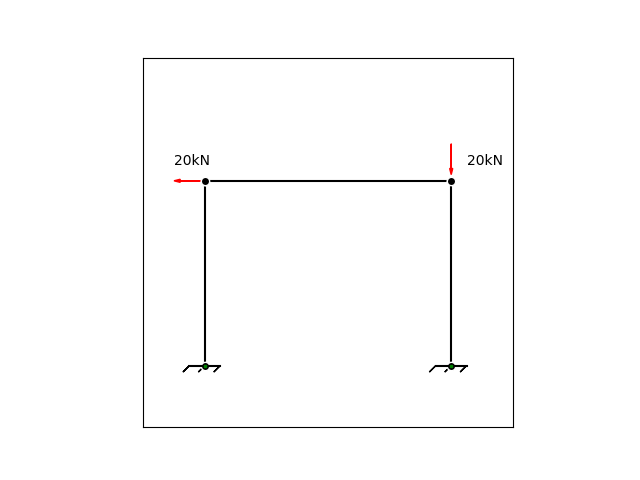
图1是一个用py进行的简单绘图的平面钢架结构,虽然很简单,我们尝试用matlab求解出底部节点的支反力。
先是图片代码
import numpy as np
import matplotlib.pyplot as plt
from matplotlib.lines import Line2D


n1=(0,0)
n2=(0,3)
n3=(4,3)
n4=(4,0)
nds=[n1,n2,n3,n4]
k1=(-0.25,0)
k2=(0.25,0)
kds=[k1,k2]
k3=(4.25,0)
k4=(3.75,0)
kds2=[k3,k4]
#创建图标
fig=plt.figure()

ax=fig.add_subplot(111,aspect='equal')

ax.set_xlim(-1,5)
ax.set_ylim(-1,5)
ax.set_xticks([])
ax.set_yticks([])

    #绘制直线
for i in range(3):
    x,y=[nds[i][0],nds[i+1][0]],[nds[i][1],nds[i+1][1]]
    line=Line2D(x,y,color='k',linewidth=1.5,marker='o',markeredgecolor='w',ms='6')
    ax.add_line(line)

for i in range(1):
    x1, y1 = [kds[i][0], kds[i + 1][0]], [kds[i][1], kds[i + 1][1]]
    line = Line2D(x1, y1, color='k', linewidth=1.5,  markeredgecolor='w', ms=6)
    ax.add_line(line)

for i in range(1):
    x2, y2 = [kds2[i][0], kds2[i + 1][0]], [kds2[i][1], kds2[i + 1][1]]
    line = Line2D(x2, y2, color='k', linewidth=1.5, markeredgecolor='w', ms=6)
    ax.add_line(line)
    #绘制支座
ax.plot(n1[0],n1[1],'gs',ms=2)
ax.plot(n4[0],n4[1],'gs',ms=2)

plt.text(-0.5,3.25, r'20kN')
plt.text(4.25,3.25, r'20kN')
    #绘制箭头
ax.arrow(4,3.6,0,-0.5,length_includes_head=True,head_length=0.1,head_width=0.05,color='r')
ax.arrow(0,3,-0.5,0,length_includes_head=True,head_length=0.1,head_width=0.05,color='r')
ax.arrow(0,0,-0.1,-0.1,length_includes_head=False,)
ax.arrow(0.25,0,-0.1,-0.1,length_includes_head=False,)
ax.arrow(-0.25,0,-0.1,-0.1,length_includes_head=False,)
ax.arrow(4,0,-0.1,-0.1,length_includes_head=False,)
ax.arrow(4.25,0,-0.1,-0.1,length_includes_head=False,)
ax.arrow(3.75,0,-0.1,-0.1,length_includes_head=False,)
plt.show()
接下来我们先创建脚本基本信息
E=210e6;A=2e-2;I=5e-5;L1=3;L2=4;L3=3;
这些图上没有标注因为太麻烦了,果然还是用专业的画图软件画会比较好。。。hhhh
接下来附上整体代码
addpath D:\matlab\toolbox\M-Files
%基本信息,
E=210e6;
A=2e-2;
I=5e-5;
L1=3;
L2=4;
L3=3;
%单根刚度计算
k1=PlaneFrameElementStiffness(E,A,I,L1,90);
k2=PlaneFrameElementStiffness(E,A,I,L2,0);
k3=PlaneFrameElementStiffness(E,A,I,L3,270);
%建立整体刚度矩阵
K=zeros(12,12);
K=PlaneFrameAssemble(K,k1,1,2);
K=PlaneFrameAssemble(K,k2,2,3);
K=PlaneFrameAssemble(K,k3,3,4)
%引入边界条件,如图每个力为20kN,支座固支
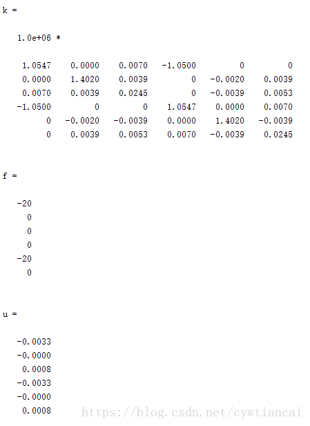
k=K(4:9,4:9)
f=[-20;0;0;0;-20;0]
u=k\f
%后处理
U=[0;0;0;u;0;0;0]
F=K*U
一个简单的前处理+后处理过程
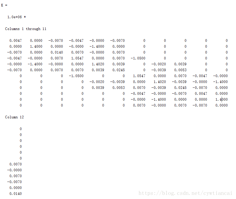
首先我们得到的第一个就是刚度矩阵
是一个12*12的矩阵,因为4个点分别包括平面xy加上转角
求出了支点的位移
再根据F=K*U
求出了所有支点的受力情况。其实后处理还有很多功能,包括求单元力,以及绘制剪力弯矩图,这次就介绍到这,下次会用feon和abaqus软件进行计算对比。


