Verilog语法_7(SPI接口驱动)
September 28, 2016
作者:dengshuai_super
出处:http://blog.csdn.net/dengshuai_super/article/details/52688654
声明:转载请注明作者及出处。
百度百科定义:
SPI(Serial Peripheral Interface–串行外设接口)总线系统是一种同步串行外设接口,它可以使MCU与各种外围设备以串行方式进行通信以交换信息。SPI有三个寄存器分别为:控制寄存器SPCR,状态寄存器SPSR,数据寄存器SPDR。外围设备包括FLASHRAM、网络控制器、LCD显示驱动器、A/D转换器和MCU等。
SPI接口应用:
串行flash的读写擦除命令通过SPI接口进行通信。
CPU芯片与FPGA通过SPI接口进行通信。
其他功能集成电路芯片参数寄存器配置。(例如DAC芯片内部有很多寄存器(因为芯片有很多功能,要通过设置寄存器不同的开关来打开或关闭相应的功能,一上电去初始化寄存器)需要我们去配置。FPGA一上电也是通过配置芯片里边来读取数据,然后配置FPGA内部的SRAM。FPGA是读取FLASH里边的串行数据,读取完校验完才配置到我们的FPGA的SRAM中去)
速度比串口快,而且是同步传输。
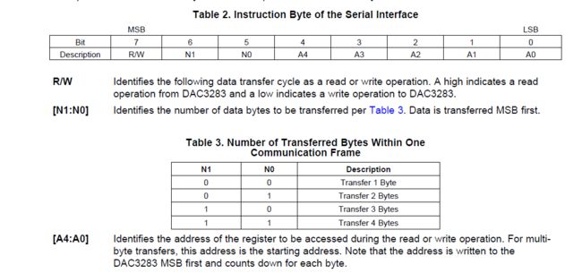
某DAC芯片的SPI配置时序(数字模拟转换器(英语:Digital to analog converter,英文缩写:DAC)是一种将数字信号转换为模拟信号(以电流、电压或电荷的形式)的设备。)
SPI(Serial Peripheral Interface)

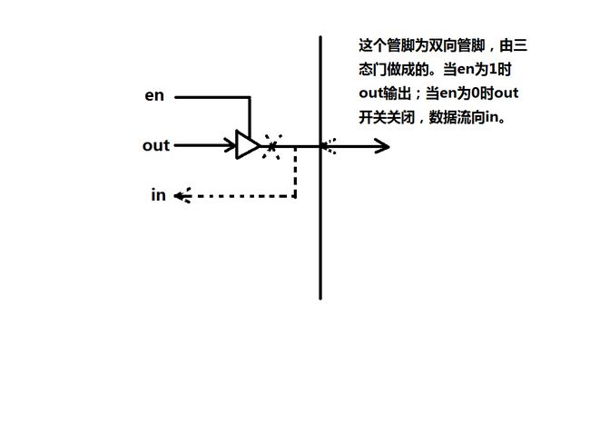
下边是四线SPI(三线的SPI是把SDI和SDO合并成了一个SDIO双向的)
SCLK主机给从机的系统时钟
SDI主机输出给从机的数据。
SDO从机输出给主机的数据
CS:chip select 片选信号,此信号可以使一个主机控制多个从机,此信号有效表示此从机被选中通信。(片选可以理解成选片,很多芯片挂在同一总线上的时候,需要有一个信号来区别总线上的数据和地址由哪个芯片处理,这时就需要一个片选信号CS(chip select),一般是在划分地址空间时,由逻辑电路产生的。在数字电路设计中,一般开路输入管脚呈现为高电平,因此片选信号绝大多数情况下是一个低电平。
带-n的是低电平有效;不带的是高电平有效。)
在这种有命令和数据的情况下,可以把命令和数据都存到我们的RAM中去,这样我们在读出来的时候就按照比特,一个比特一个比特的给它发过去就可以了,可以简化逻辑。
这样虽然占用了更多的ram空间,但是节省逻辑空间。因为Block Memory它大小是固定的,比如说它里边的深度是256,比如cycloneIV最小的是m9k,那么它也会占用整个9k的memory,就算用里面的一点也会把整块占用,布局布线和综合。
因此可以把存储数据和命令都存储到ram,方便我们操作。
案例实现:首先数据存储到RAM或ROM中,然后再从RAM或ROM中读出来再发送。
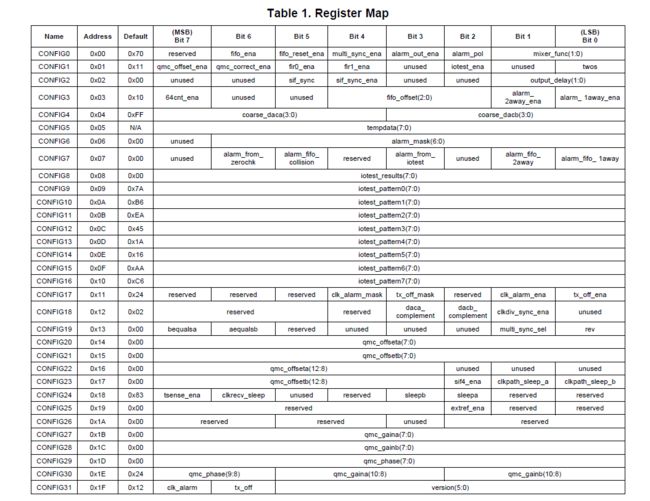
这里有32个寄存器,像这种配置,有些时候我们配置的时候不能连续的配置两个寄存器,每配置完一个寄存器要把使能拉高,停一拍。做FLASH擦出或读写的时候中间有个保护时间,就是说你两次命令需要间隔多长时间。我们中间要隔一定的周期数再发第二个命令。所以,我们发送完一个数据的时候,我们等待一段时间再去发送第二个命令。所以我们把这个顺序流程定义成一个状态机,我们用状态机的方式去控制它的流程。
状态迁移图:
图片
建立一个ram的IP核:
//D:\VivadoProjects\FPGA_From_e_to_c\ex_7\quartus_prj\ipcore_dir\ram_16x32_sr_inst.v
ram_16x32_sr    ram_16x32_sr_inst (
    .address ( address_sig ),
    .clock ( clock_sig ),
    .data ( data_sig ),
    .wren ( wren_sig ),
    .q ( q_sig )
    );
建立一个.mif文件,用来初始化ram:
--D:\VivadoProjects\FPGA_From_e_to_c\ex_7\quartus_prj\ipcore_dir\ram_16x32_sr.mif
-- Copyright (C) 1991-2013 Altera Corporation
-- Your use of Altera Corporation's design tools, logic functions
-- and other software and tools, and its AMPP partner logic
-- functions, and any output files from any of the foregoing
-- (including device programming or simulation files), and any
-- associated documentation or information are expressly subject
-- to the terms and conditions of the Altera Program License
-- Subscription Agreement, Altera MegaCore Function License
-- Agreement, or other applicable license agreement, including,
-- without limitation, that your use is for the sole purpose of
-- programming logic devices manufactured by Altera and sold by
-- Altera or its authorized distributors.  Please refer to the
-- applicable agreement for further details.

-- Quartus II generated Memory Initialization File (.mif)

WIDTH=16;
DEPTH=32;

ADDRESS_RADIX=UNS;
DATA_RADIX=BIN;

CONTENT BEGIN
  0    :   0000000001110000;
  1    :   0000000100110001;
  2    :   0000001000000000;
  3    :   0000001100010000;
  4    :   0000010011111111;
  5    :   0000010100000000;
  6    :   0000011000000000;
  7    :   0000011100000000;
  8    :   0000100000000000;
  9    :   0000100101010101;
  10   :   0000101010101010;
  11   :   0000101101010101;
  12   :   0000110010101010;
  13   :   0000110101010101;
  14   :   0000111010101010;
  15   :   0000111101010101;
  16   :   0001000010101010;
  17   :   0001000100100100;
  18   :   0001001000000010;
  19   :   0001001111000010;
  20   :   0001010000000000;
  21   :   0001010100000000;
  22   :   0001011000000000;
  23   :   0001011100000100;
  24   :   0001100010000011;
  25   :   0001100100000000;
  26   :   0001101000000000;
  27   :   0001101100000000;
  28   :   0001110000000000;
  29   :   0001110100000000;
  30   :   0001111000100100;
  31   :   0001111101010010;

END;
//D:\VivadoProjects\FPGA_From_e_to_c\ex_7\design\spi_ctrl.v
module spi_ctrl(
            input       wire                sclk,//主机给从机的系统时钟50Mhz
            input       wire                rst_n,
            input       wire                work_en,//触发配置操作的使能,属于引入的一个让状态机是否工作的工作使能。
            output      reg                 conf_end,//配置结束,为的是和其他模块相连的时候有个标志
            output      wire                spi_clk,//50-60Mhz
            output    wire              spi_sdi,//SDI主机输出给从机的数据。
            output    wire              spi_csn,//片选信号可以使一个主机控制多个从机,此信号有效表示此从机被选中通信。
            input     wire              spi_sdo//从机输出给主机的数据;;读输入管脚不进行编程
);

parameter       IDLE  = 5'b0_0001;
parameter       WAIT  = 5'b0_0010;
parameter       R_MEM = 5'b0_0100;
parameter       W_REG = 5'b0_1000;
parameter       STOP  = 5'b1_0000;

parameter   H_DIV_CYC  =        5'd25 - 1;

//先来一个分频

reg     [4:0]       state;//状态机的寄存器变量编码方式采用独热码
reg     [4:0]       div_cnt;//分频器
reg                     clk_p=1'b0;//产生数据
wire                    clk_n;//提供spi的从机作为数据采集,clk_n上升沿前边用于建立时间,后边用于保持时间,达到时序最优化
reg                     pose_flag;//标志上升沿
reg     [3:0]       wait_cnt;
reg   [3:0]   shift_cnt;
reg   [4:0]   r_addr=0;
wire  [15:0]  r_data;
wire          wren;
reg   [15:0]  shift_buf;//存储读出来的16位数据,
reg           data_end;
reg                     sdi;
reg                     csn;
reg                     tck;


//分频计数器
always @(posedge sclk or rst_n)
            if(rst_n == 1'b0)
                    div_cnt <= 5'd0;
            else if(div_cnt == H_DIV_CYC)
                    div_cnt <= 'd0;
            else
                    div_cnt <=div_cnt + 1'b1;//当sclk震了24次之后div_cnt出现高电平,然后减到0,在震24次出现下一个高电平,一次把原来的sclk分频了50倍

//分频时钟不允许做寄存器的触发时钟,也就是不能写在always块的触发列表中
always @(posedge sclk or rst_n)
            if(rst_n == 1'b0)
                    clk_p <= 1'b0;
            else if(div_cnt == H_DIV_CYC)
                    clk_p <= ~clk_p;

assign clk_n =~clk_p;

//产生一个标志信号,用于分频同步的标志信号
always @(posedge sclk or negedge rst_n)
                if(rst_n == 1'b0)
                        pose_flag <= 1'b0;
                else if(clk_p == 1'b0 && div_cnt == H_DIV_CYC)
                        pose_flag <= 1'b1;
                else
                        pose_flag <= 1'b0;


//等待计数器
always @(posedge sclk or negedge rst_n)
            if(rst_n == 1'b0)
                    wait_cnt    <= 'd0;
            else if(state == WAIT && pose_flag ==1'b1)
                    wait_cnt <= wait_cnt + 1'b1;
            else if(state !=WAIT)
                    wait_cnt <= 4'd0;

//fsm
always @(posedge sclk or negedge rst_n)
            if(rst_n == 1'b0)
                        state <=IDLE;
            else case(state)
                                IDLE : if(work_en ==1'b1)
                                                    state <=WAIT;
                                WAIT : if(wait_cnt[3] == 1'b1)//当计数到第八次的时候
                                                    state <=R_MEM;
                                R_MEM: state <= W_REG;
                                W_REG: if(shift_cnt == 4'd15 && pose_flag == 1'b1 && data_end != 1'b1)
                                                    state <=WAIT;
                                             else if(shift_cnt == 4'd15 && pose_flag == 1'b1 && data_end == 1'b1)
                                                    state <= STOP;
                                STOP:  state <= STOP;
                                default: state <= IDLE;
                 endcase

always @(posedge sclk or negedge rst_n)
            if(rst_n == 1'b0)
                shift_cnt <= 'd0;
          else if(state == W_REG && pose_flag == 1'b1)
            shift_cnt <= shift_cnt + 1'b1;
          else if(state != W_REG)
            shift_cnt <=4'd0;

//读memory的地址产生
always @(posedge sclk or negedge rst_n)
            if(rst_n ==1'b0)
                    r_addr <= 'd0;
            else if(state == R_MEM)
                    r_addr <= r_addr + 1'b1;

//data_end 最后一个需要移位的数据
always @(posedge sclk or negedge rst_n)
                if(rst_n == 1'b0)
                        data_end <= 1'b0;
                else if(state == R_MEM && (&r_addr)==1'b1 )// 11111按位与等效于r_addr == 5'd31
                        data_end <= 1'b1;

assign wren =1'b0;

always @(posedge sclk or negedge rst_n)
            if(rst_n == 1'b0)
                shift_buf <= 'd0;
            else if(state == R_MEM)
                shift_buf <= r_data;
            else if(state == W_REG && pose_flag == 1'b1)
                shift_buf <={shift_buf[14:0],1'b1};

//数据输出
always @(posedge sclk or negedge rst_n)
                if(rst_n == 1'b0)
                        sdi <=1'b0;
                else if(state == W_REG && pose_flag == 1'b1)
                        sdi <=shift_buf[15];
                else if(state != W_REG)
                        sdi <= 1'b0;

always @(posedge sclk or negedge rst_n)
                if(rst_n == 1'b0)
                        csn <= 1'b1;
                else if(state == W_REG)
                        csn <=1'b0;
                else
                        csn <=1'b1;

always @ (posedge sclk or negedge rst_n)
                if(rst_n == 1'b0)
                        tck <= 1'b0;
                else if(state == W_REG)
                        tck <= clk_n;
                else
                        tck <=1'b0;

assign spi_clk = tck;
assign spi_csn = csn;
assign spi_sdi = sdi;

always @ (posedge sclk or negedge rst_n)
            if(rst_n == 1'b0)
                    conf_end <= 1'b0;
            else if(state == STOP)
                    conf_end <= 1'b1;

ram_16x32_sr    ram_16x32_sr_inst (
    .address ( r_addr ),//读地址
    .clock ( sclk ),
    .data ( 16'd0 ),//写数据
    .wren ( wren ),//写使能高有效,读使能低有效
    .q ( r_data )//读数据
    );
endmodule
testbench:
//tb_ex_spi.v
`timescale 1ns/1ns

module tb_ex_spi;
reg         sclk,rst_n;
reg         work_en;

initial begin
                rst_n = 0;
                sclk  =0;
                #100;
                rst_n = 1;
end

initial begin
                    work_en = 0;
                    #150
                    work_en = 1;
end

always # sclk = ~sclk;

spi_ctrl(
            .sclk                           (sclk),//主机给从机的系统时钟50Mhz
            .rst_n                      (rst_n),
            .work_en                    (work_en),//触发配置操作的使能,属于引入的一个让状态机是否工作的工作使能。
            .conf_end                   (),//配置结束,为的是和其他模块相连的时候有个标志
            .spi_clk                    (),//50-60Mhz
            .spi_sdi                    (),//SDI主机输出给从机的数据。
            .spi_csn                    (),//片选信号可以使一个主机控制多个从机,此信号有效表示此从机被选中通信。
            .spi_sdo                    ()  //从机输出给主机的数据;;读输入管脚不进行编程
);

endmodule
将D:\altera\13.1\quartus\eda\sim_lib\altera_mf.v (ram仿真需要的库文件)拷贝到sim\altera_lib目录下。
把ram_16x32_sr.mif拷贝到sim目录下


