STM32 控制LED灯
STM32 控制LED灯
一、简述
记--直接通过设置寄存器来控制LED灯、通过使用STM库函数来控制LED灯实现流水灯。
例子1:链接: https://pan.baidu.com/s/13KAa6U0HVik47MSZ0wMuvQ 提取码: ejq8
例子2:链接: https://pan.baidu.com/s/115aMtD6nhYanusHsfmM9HQ 提取码: bys4
例子1 通过设置寄存器来控制LED灯
二、效果
LED0闪烁
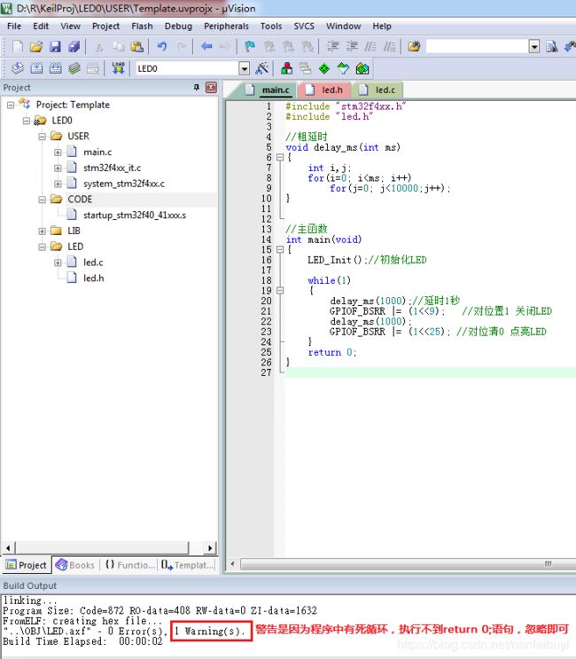
三、工程结构
四、源文件
main.c文件
#include "stm32f4xx.h"
#include "led.h"

//粗延时
void delay_ms(int ms)
{
	int i,j;
	for(i=0; i
led.h文件
#ifndef __LED_H
#define __LED_H
#include "stm32f4xx.h"

//定义宏为寄存器地址的解引用,到时候直接操作宏就是操作寄存器,方便编程。
//加上volatile关键字是为了防止编译器进行优化,导致操作寄存器地址失败。(提醒编译器,这个值是容易变化的。)
#define RCC_AHB1ENR		*(volatile unsigned int *)(0x40023800+0x30)  //外设时钟使能寄存器
#define GPIOF_MODER		*(volatile unsigned int *)(0x40021400+0x00)  //GPIO端口模式寄存器
#define GPIOF_OTYPER	*(volatile unsigned int *)(0x40021400+0x04)  //GPIO端口输出类型寄存器
#define GPIOF_OSPEEDR	*(volatile unsigned int *)(0x40021400+0x08)  //GPIO端口速度寄存器
#define GPIOF_PUPDR 	*(volatile unsigned int *)(0x40021400+0x0C)  //GPIO端口上拉/下拉寄存器
#define GPIOF_BSRR 	    *(volatile unsigned int *)(0x40021400+0x18)  //GPIO端口置位/ 复位寄存器


void LED_Init(void);


#endif
led.c文件
#include "led.h"


void LED_Init(void)
{
	//使能GPIOF组时钟
	RCC_AHB1ENR |= (1<<5);   //对位置1

	//设置GPIO口的模式
	GPIOF_MODER &= ~(1<<19); //对位清0
	GPIOF_MODER |=  (1<<18); //对位置1

	//设置输出模式为推挽模式
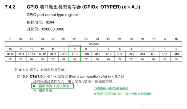
	GPIOF_OTYPER  &= ~(1<<9); //对位清0

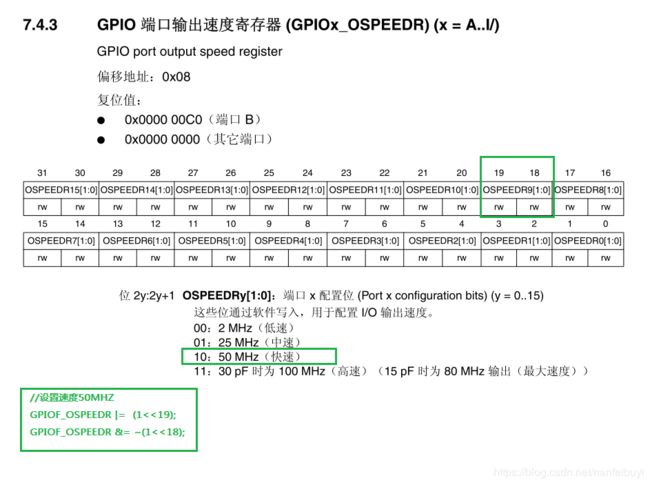
	//设置速度50MHZ
	GPIOF_OSPEEDR |=  (1<<19);
	GPIOF_OSPEEDR &= ~(1<<18);

	//设置为上拉模式
	GPIOF_PUPDR &= ~(1<<19); //对位清0
	GPIOF_PUPDR |=  (1<<18); //对位置1


}
五、总结
5.1 LED灯的硬件视图
(在开发板上找到LED的位置)
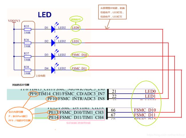
5.2 LED灯的原理图
查看GEC-M4原理图2016-07-29.pdf原理图文件
找到LED灯对应的芯片引脚之后,我们可以通过控制该引脚的电平输出来控制LED灯的两灭。
5.3 点亮LED0
相关文档:STM32F4xx中文参考手册.pdf
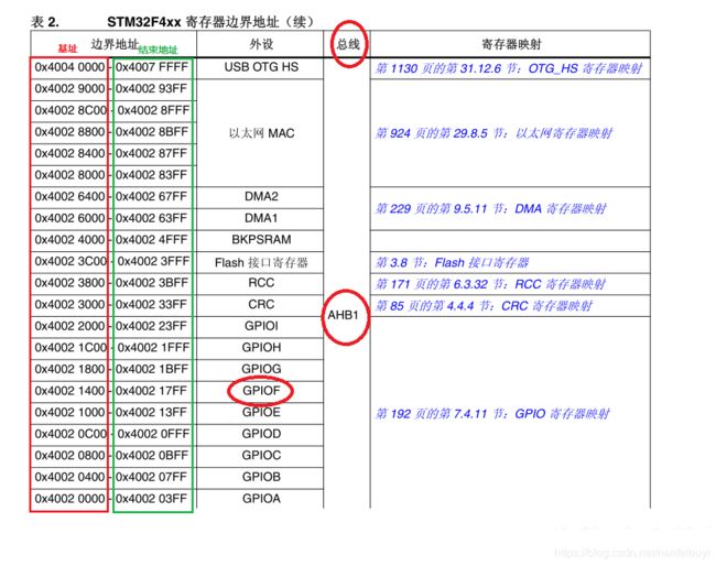
相关寄存器物理地址=基址+偏移地址
//定义宏为寄存器地址的解引用,到时候直接操作宏就是操作寄存器,方便编程。
//加上volatile关键字是为了防止编译器进行优化,导致操作寄存器地址失败。(提醒编译器,这个值是容易变化的。)
#define RCC_AHB1ENR		*(volatile unsigned int *)(0x40023800+0x30)  //外设时钟使能寄存器 AHB1总线
#define GPIOF_MODER		*(volatile unsigned int *)(0x40021400+0x00)  //GPIO端口模式寄存器 F组
#define GPIOF_OTYPER	*(volatile unsigned int *)(0x40021400+0x04)  //GPIO端口输出类型寄存器 F组
#define GPIOF_OSPEEDR	*(volatile unsigned int *)(0x40021400+0x08)  //GPIO端口速度寄存器 F组
#define GPIOF_PUPDR 	*(volatile unsigned int *)(0x40021400+0x0C)  //GPIO端口上拉/下拉寄存器 F组
#define GPIOF_BSRR 	    *(volatile unsigned int *)(0x40021400+0x18)  //GPIO端口置位/ 复位寄存器 F组
步骤1 使能GPIOF组时钟 (LED0对应PF9引脚,GPIOF外设寄存器接在AHB1总线上)
设置外设时钟使能寄存器RCC AHB1 (RCC_AHB1ENR)
外设时钟使能寄存器物理地址=基址+偏移地址 ==》0x40023800+0x30=0x40023830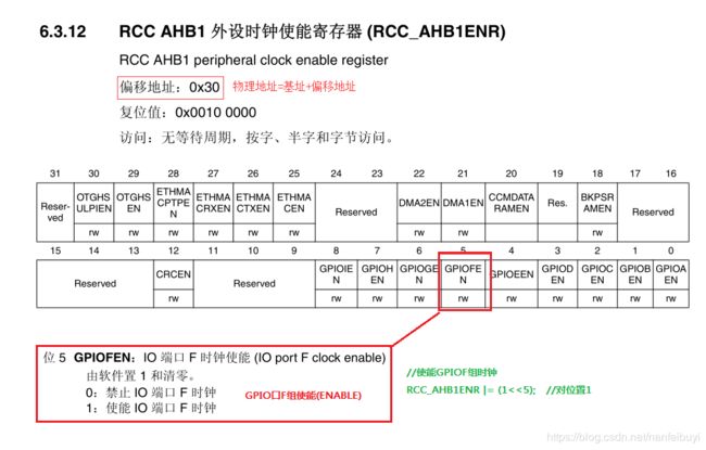
步骤2:设置GPIO口的模式
GPIO 端口模式寄存器的地址:0x40021400+0x00=0x40021400
步骤3: 设置输出模式为推挽模式
GPIO端口输出类型寄存器地址: 0x40021400+0x04
步骤4:设置GPIO端口速度寄存器
GPIO端口速度寄存器 地址:0x40021400+0x08
步骤5:设置GPIO端口上拉/下拉寄存器
GPIO端口上拉/下拉寄存器地址:0x40021400+0x0C
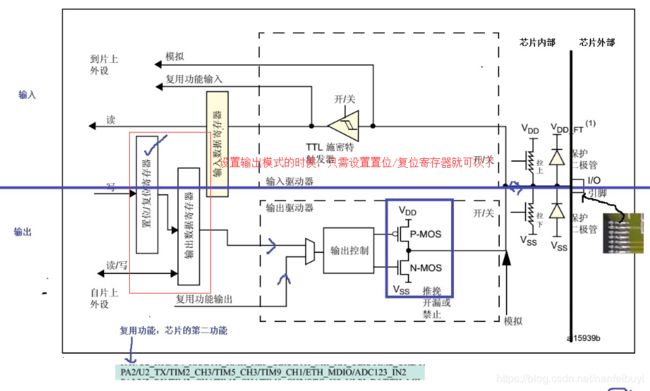
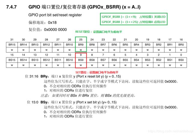
步骤6:设置GPIO 端口置位/ 复位寄存器 (设置引脚电平)
GPIO 端口置位/ 复位寄存器地址:0x40021400+0x18
例子2 通过使用STM32库函数来控制LED灯--流水灯
二、效果
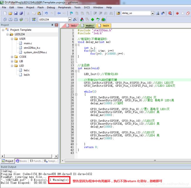
从LED1到LED4轮流亮灭
三、工程结构
四、源文件
main.c文件
#include "stm32f4xx.h"
#include "led.h"

//粗延时(不精确延时)
void delay_ms(int ms)
{
	int i,j;
	for(i=0; i
led.h文件
#ifndef __LED_H
#define __LED_H
#include "stm32f4xx.h"

void LED_Init(void);

#endif
led.c文件
#include "led.h"


void LED_Init(void)
{
	GPIO_InitTypeDef GPIO_InitStruct;

	//初始化GPIOF组时钟
	RCC_AHB1PeriphClockCmd(RCC_AHB1Periph_GPIOF, ENABLE);//LED1 LED2   引脚9、引脚10
	//初始化GPIOE组时钟
	RCC_AHB1PeriphClockCmd(RCC_AHB1Periph_GPIOE, ENABLE);//LED3 LED4   引脚13、引脚14

	//设置引脚为输出模式、速度为50MHZ,输出类型为推挽,上拉方式
	GPIO_InitStruct.GPIO_Pin 	= GPIO_Pin_9|GPIO_Pin_10;  		//引脚9、引脚10
	GPIO_InitStruct.GPIO_Mode 	= GPIO_Mode_OUT;	//输出
	GPIO_InitStruct.GPIO_Speed	= GPIO_Speed_50MHz; //速度
	GPIO_InitStruct.GPIO_OType	= GPIO_OType_PP; 	//推挽
	GPIO_InitStruct.GPIO_PuPd	= GPIO_PuPd_UP;  	//上拉
	//初始化GPIOF组引脚
	GPIO_Init(GPIOF,&GPIO_InitStruct);

	//设置引脚为输出模式、速度为50MHZ,输出类型为推挽,上拉方式
	GPIO_InitStruct.GPIO_Pin 	= GPIO_Pin_13|GPIO_Pin_14;  		//引脚13、引脚14
	GPIO_InitStruct.GPIO_Mode 	= GPIO_Mode_OUT;	//输出
	GPIO_InitStruct.GPIO_Speed	= GPIO_Speed_50MHz; //速度
	GPIO_InitStruct.GPIO_OType	= GPIO_OType_PP; 	//推挽
	GPIO_InitStruct.GPIO_PuPd	= GPIO_PuPd_UP;  	//上拉
	//初始化GPIOE组引脚
	GPIO_Init(GPIOE,&GPIO_InitStruct);

}
五、总结
5.1 相关函数
void RCC_AHB1PeriphClockCmd(uint32_t RCC_AHB1Periph, FunctionalState NewState);//初始化外设时钟函数
void GPIO_Init(GPIO_TypeDef* GPIOx, GPIO_InitTypeDef* GPIO_InitStruct);//初始化引脚
设置引脚电平:
void GPIO_SetBits(GPIO_TypeDef* GPIOx, uint16_t GPIO_Pin);//置位,例子中为高电平
void GPIO_ResetBits(GPIO_TypeDef* GPIOx, uint16_t GPIO_Pin);复位,例子中是低电平
