一种软阴影的实现方法
转载自:http://hi.baidu.com/laizhishen/blog/item/b4c219dee23df1e177c63851.html
软阴影www.GameDev.net 作者:Anirudh.S Shastry
http://www.gamedev.net/reference/articles/article2193.asp
译者:赟赟
介绍
最初,动态阴影技术只有在有限的几种情况下才能实现。但是,随着强大的可编程图形硬件的面世,动态阴影技术已经完全取代了以前的如light map这样的静态阴影技术及像projected shadows这样的半动态阴影技术。目前两种流行的动态阴影技术分别是shadow volumes[来源:GameRes.com]和shadow mapping。
近况
shadow volumes技术是一种基于几何形体的技术,它需要几何体在一定方向的灯光下的轮廓去产生一个封闭的容积,然后通过光线的投射就可以决定场景的阴影部分(常常使用模板缓冲去模拟光线的投射)。这项技术是像素精确的,不会产生任何的锯齿现象,但是与其他的技术一样,它也有缺点。最主要的两个问题一是极度依赖几何形体,二是需要非常高的填充率。由于这些缺点,使得shadow mapping技术渐渐地变得更为流行起来。
阴影映射技术是一种图像空间的技术,它首先在以光源位置作为视点的情况下渲染整个场景的深度信息,然后再使用这些深度信息去决定场景的哪一部分是处于阴影之中。虽然这项技术有许多优点,但它有锯齿现象并且依赖z-缓冲技术。不过它的优点足以抵消它的这些缺点,因此本文选用了这项技术。
软阴影
硬阴影破坏了场景的真实性,因此,我们必须仿造软阴影来提升场景的可视效果。许多狂热的学者都拿出了描述软阴影技术的论文。但实际上,这些技术大部分都是很难在一个较为复杂的场景下实现实时效果。直到我们拥有了能克服这些技术局限性的硬件后,我们才真正的采用了这些方法。
本文采用了基于图像空间的方法,并利用shadow mapping技术来产生软阴影。这个方法不能产生完美的阴影,因为没有真正的模拟出本影和半影,但它不仅仅可以解决阴影映射技术的锯齿现象,还能以赏心悦目的软阴影来提升场景的可视效果。
那么它如何工作?
首先,我们生成阴影映射图(shadow map),具体方法是以光源位置为视点,将场景的深度信息渲染到浮点格式的缓冲中去。然后我们不是像通常那样在阴影下渲染场景,而是将阴影区域渲染到一幅屏幕大小的缓冲中去,这样就可以使用bloom filter进行模糊并将它投射回屏幕空间中使其显示在屏幕上。是不是很简单?
本文只处理了聚光灯源这种情况,但可以很方便的推广到点光源上。
下面是具体步骤:
通过将深度信息写入浮点纹理的方法产生阴影映射图(shadow map)。
深度比较后将场景的阴影部分渲染到定点纹理,此时不要任何的灯光。
使用bloom filter模糊上一步的纹理,本文采用了separable Gaussian filter,也可用其他的方法。
在所有的光源下将上一步模糊后的纹理投射到屏幕空间中,从而得到最终的效果。
步骤一:渲染阴影映射图(shadow map)
首先,我们需要创建一个能保存屏幕深度信息的纹理。因为要把这幅纹理作为render target,所以我们还要创建一个表面(surface)来保存纹理的表面信息。由于深度信息值的范围很大因此这幅纹理必须是浮点类型的。R32F的格式有足够的精度可以满足我们的需要。下面是创建纹理的代码片断:
// Create the shadow map
if( FAILED( g_pd3dDevice->CreateTexture( SHADOW_MAP_SIZE,
SHADOW_MAP_SIZE, 1, D3DUSAGE_RENDERTARGET,
D3DFMT_R32F, D3DPOOL_DEFAULT, &g_pShadowMap,
NULL ) ) )
{
MessageBox( g_hWnd, "Unable to create shadow map!",
"Error", MB_OK | MB_IConERROR );
return E_FAIL;
}
// Grab the texture's surface
g_pShadowMap->GetSurfaceLevel( 0, &g_pShadowSurf );
为了完成阴影映射图,我们要把场景的深度信息渲染到阴影映射图中。为此在光源的世界-视点-投影变换矩阵(world-view-projection matrix)下渲染整个场景。下面是构造这些矩阵的代码:
// Ordinary view matrix
D3DXMatrixLookAtLH( &matView, &vLightPos, &vLightAim, &g_vUp );
// Projection matrix for the light
D3DXMatrixPerspectiveFovLH( &matProj, D3DXToRadian(30.0f),
1.0f, 1.0f, 1024.0f );
//实际上作者在例程中使用的是D3DXMatrixOrthoLH( &matProj, 45.0f, 45.0f, 1.0f, 1024.0f )。这个函数所构造的project矩阵与D3DXMatrixPerspectiveFovLH()构造的不同之处在于:它没有透视效果。即物体的大小与视点和物体的距离没有关系。显然例程中模拟的是平行光源(direction light),而这里模拟的是聚光灯源(spot light不知翻译得对不对?)
// Concatenate the world matrix with the above
// two to get the required matrix
matLightViewProj = matWorld * matView * matProj;
下面是渲染场景深度的顶点渲染和像素渲染的代码:
// Shadow generation vertex shader
struct VSOUTPUT_SHADOW
{
float4 vPosition : POSITION;
float fDepth : TEXCOORD0;
};
VSOUTPUT_SHADOW VS_Shadow( float4 inPosition : POSITION )
{
// Output struct
VSOUTPUT_SHADOW OUT = (VSOUTPUT_SHADOW)0;
// Output the transformed position
OUT.vPosition = mul( inPosition, g_matLightViewProj );
// Output the scene depth
OUT.fDepth = OUT.vPosition.z;
return OUT;
}
这里我们将顶点的位置与变换矩阵相乘,并将变换后的z值作为深度。在像素渲染中将深度值以颜色(color)的方式输出。
float4 PS_Shadow( VSOUTPUT_SHADOW IN ) : COLOR0
{
// Output the scene depth
return float4( IN.fDepth, IN.fDepth, IN.fDepth, 1.0f );
}
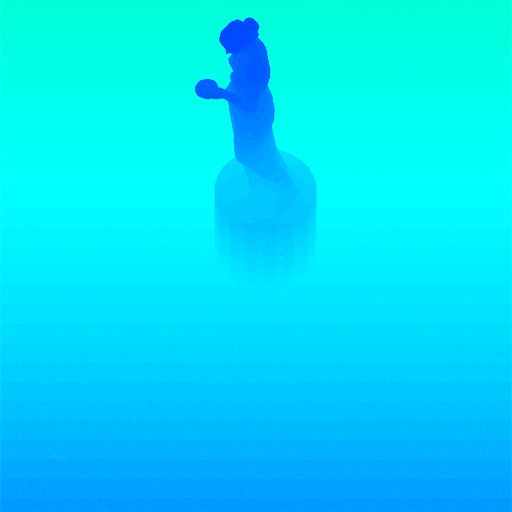
瞧,我们完成了阴影映射图,下面就是以颜色方式输出的阴影映射图,深蓝色部分表明较小的深度值,浅蓝色部分表明较大的深度值。
步骤二:将带阴影的场景渲染到缓冲中
下面,我们要把场景的带阴影的部分渲染到并不立即显示的缓冲中,使我们可以进行模糊处理,然后再将它投射回屏幕。首先把场景的阴影部分渲染到一幅屏幕大小的定点纹理中。
// Create the screen-sized buffer map
if( FAILED( g_pd3dDevice->CreateTexture( SCREEN_WIDTH,
SCREEN_HEIGHT, 1, D3DUSAGE_RENDERTARGET,
D3DFMT_A8R8G8B8, D3DPOOL_DEFAULT,
&g_pScreenMap, NULL ) ) )
{
MessageBox( g_hWnd, "Unable to create screen map!",
"Error", MB_OK | MB_IConERROR );
return E_FAIL;
}
// Grab the texture's surface
g_pScreenMap->GetSurfaceLevel( 0, & g_pScreenSurf );
为了获得投影纹理坐标(projective texture coordinates),我们需要一个纹理矩阵,作用是把投影空间(projection space)中的位置变换到纹理空间(texture space)中去。
// Generate the texture matrix
float fTexOffs = 0.5 + (0.5 / (float)SHADOW_MAP_SIZE);
D3DXMATRIX matTexAdj( 0.5f, 0.0f, 0.0f, 0.0f,
0.0f, -0.5f, 0.0f, 0.0f,
0.0f, 0.0f, 1.0f, 0.0f,
fTexOffs, fTexOffs, 0.0f, 1.0f );
//这个矩阵是把projection space中范围为[-1,1]的x,y坐标值转换到纹理空间中
//[0,1]的范围中去。注意y轴的方向改变了。那个(0.5 / (float)SHADOW_MAP_SIZE)
//的值有什么作用我还不清楚,原文也没有说明。
matTexture = matLightViewProj * matTexAdj;
//---------------------------------------------------------------------------------------------------------------------------------
纹理坐标 0~1 。0.5 / (float)SHADOW_MAP_SIZE ,图片大小为SHADOW_MAP_SIZE所以推断是偏移0.5个像素
float fTexOffs = 0.5; //+ (0.5 / (float)SHADOW_MAP_SIZE);
(x,y,z,1)* matTexAdj =
x = 0.5*x + y*0 + z*0 + 0.5*1 = 0.5*x + 0.5 = (1 + x) / 2
y = 0*y - 0.5*y + z*0 + 0.5*1 = -0.5*y + 0.5 = (1 - y) / 2
//---------------------------------------------------------------------------------------------------------------------------------
我们像往常那样通过深度的比较来获得阴影因数,但随后并不是像平常那样输出整个照亮了的场景,我们只输出阴影因数。下面的顶点渲染和像素渲染完成这个工作。
// Shadow mapping vertex shader
struct VSOUTPUT_UNLIT
{
float4 vPosition : POSITION;
float4 vTexCoord : TEXCOORD0;
float fDepth : TEXCOORD1;
};
VSOUTPUT_UNLIT VS_Unlit( float4 inPosition : POSITION )
{
// Output struct
VSOUTPUT_UNLIT OUT = (VSOUTPUT_UNLIT)0;
// Output the transformed position
OUT.vPosition = mul( inPosition, g_matWorldViewProj );
// Output the projective texture coordinates
OUT.vTexCoord = mul( inPosition, g_matTexture );
// Output the scene depth
OUT.fDepth = mul( inPosition, g_matLightViewProj ).z;
return OUT;
}
我们采用percentage closer filtering (PCF)来平滑锯齿边缘。为了完成“PCF”,我们简单的对周围8个纹理点进行采样,并取得它们深度比较的平均值。
// Shadow mapping pixel shader
//注意这里采用的是tex2Dproj()函数以及转换到纹理空间的向量(x,y,z,w)对纹理进//行采样。这与d3d9sdk中shadowmap例子用tex2D()及向量(x,y)进行采样不同。具体//区别及原因很容易从程序中看出,我就不再啰嗦了。
---------------------------------------------------------------------------------------------------------------------------
知道原因后,其实直接用tex2D()来实现tex2Dproj()的功能也仅仅是在纹理坐标上手动除以其最后一个分量(这里补充一下:其实tex2D本身就已经有tex2Dproj的功能,完全可以代替tex2Dproj使用!说白了就是有用tex2Dproj的地方都可以用tex2D代替,反之不成立。这是我后来在Cg Reference中发现的,之前没有注意到而已啦),如下:
float4 textureColor = tex2Dproj(projectiveMap,
                                  texCoordProj);

  float4 textureColor = tex2D(projectiveMap,
                                  texCoordProj.xy/texCoordProj.w);
----------------------------------------------------------------------------
float4         PS_Unlit( VSOUTPUT_UNLIT IN ) : COLOR0
{
         // Generate the 9 texture co-ordinates for a 3x3 PCF kernel
         float4 vTexCoords[9];
         // Texel size
         float fTexelSize = 1.0f / 1024.0f;
// Generate the tecture co-ordinates for the specified depth-map size
// 4 3 5
// 1 0 2
// 7 6 8
VTexCoords[0] = IN.vTexCoord;
vTexCoords[1] = IN.vTexCoord + float4( -fTexelSize, 0.0f, 0.0f, 0.0f );
vTexCoords[2] = IN.vTexCoord + float4( fTexelSize, 0.0f, 0.0f, 0.0f );
vTexCoords[3] = IN.vTexCoord + float4( 0.0f, -fTexelSize, 0.0f, 0.0f );
vTexCoords[6] = IN.vTexCoord + float4( 0.0f, fTexelSize, 0.0f, 0.0f );
vTexCoords[4] = IN.vTexCoord + float4( -fTexelSize, -fTexelSize, 0.0f, 0.0f );
vTexCoords[5] = IN.vTexCoord + float4( fTexelSize, -fTexelSize, 0.0f, 0.0f );
vTexCoords[7] = IN.vTexCoord + float4( -fTexelSize, fTexelSize, 0.0f, 0.0f );
vTexCoords[8] = IN.vTexCoord + float4( fTexelSize, fTexelSize, 0.0f, 0.0f );
// Sample each of them checking whether the pixel under test is shadowed or not
float fShadowTerms[9];
float fShadowTerm = 0.0f;
for( int i = 0; i < 9; i++ )
{
float A = tex2Dproj( ShadowSampler, vTexCoords[i] ).r;
float B = (IN.fDepth - 0.1f);
// Texel is shadowed
fShadowTerms[i] = A < B ? 0.0f : 1.0f;
fShadowTerm += fShadowTerms[i];
}
// Get the average
fShadowTerm /= 9.0f;
return fShadowTerm;
}
屏幕缓冲完成了,我们还需要进行模糊工作。

步骤三:对屏幕缓冲进行模糊
我们采用seperable gaussian filter模糊屏幕缓冲。但我们也可以用Poisson filter。这次的render targets是A8R8G8B8的纹理和相关的表面。我们需要两个render targets,一个进行水平阶段,一个进行垂直阶段。
// Create the blur maps
for( int i = 0; i < 2; i++ )
{
if( FAILED( g_pd3dDevice->CreateTexture( SCREEN_WIDTH,
SCREEN_HEIGHT, 1, D3DUSAGE_RENDERTARGET,
D3DFMT_A8R8G8B8, D3DPOOL_DEFAULT,
&g_pBlurMap[i], NULL ) ) )
{
MessageBox( g_hWnd, "Unable to create blur map!",
"Error", MB_OK | MB_IConERROR );
return E_FAIL;
}
// Grab the texture's surface
g_pBlurMap[i]->GetSurfaceLevel( 0, & g_pBlurSurf[i] );
}
我们用下面的代码生成15个高斯偏移量(Gaussian offsets)及他们的权重(corresponding weights)。
float GetGaussianDistribution( float x, float y, float rho )
{
float g = 1.0f / sqrt( 2.0f * 3.141592654f * rho * rho );
return g * exp( -(x * x + y * y) / (2 * rho * rho) );
}
void GetGaussianOffsets( bool bHorizontal,
D3DXVECTOR2 vViewportTexelSize,
D3DXVECTOR2* vSampleOffsets,
float* fSampleWeights )
{
// Get the center texel offset and weight
fSampleWeights[0] = 1.0f * GetGaussianDistribution( 0, 0, 2.0f );
vSampleOffsets[0] = D3DXVECTOR2( 0.0f, 0.0f );
// Get the offsets and weights for the remaining taps
if( bHorizontal )
{
for( int i = 1; i < 15; i += 2 )
{
vSampleOffsets[i + 0] = D3DXVECTOR2( i * vViewportTexelSize.x, 0.0f );
vSampleOffsets[i + 1] = D3DXVECTOR2( -i * vViewportTexelSize.x, 0.0f );
fSampleWeights[i + 0] = 2.0f * GetGaussianDistribution( float(i + 0), 0.0f, 3.0f );
fSampleWeights[i + 1] = 2.0f * GetGaussianDistribution( float(i + 1), 0.0f, 3.0f );
}
}
else
{
for( int i = 1; i < 15; i += 2 )
{
vSampleOffsets[i + 0] = D3DXVECTOR2( 0.0f, i * vViewportTexelSize.y );
vSampleOffsets[i + 1] = D3DXVECTOR2( 0.0f, -i * vViewportTexelSize.y );
fSampleWeights[i + 0] = 2.0f * GetGaussianDistribution( 0.0f, float(i + 0), 3.0f );
fSampleWeights[i + 1] = 2.0f * GetGaussianDistribution( 0.0f, float(i + 1), 3.0f );
}
}
}
为了模糊屏幕缓冲,我们将模糊映射图(blur map)作为render target,使用下面的顶点渲染和像素渲染代码渲染一个与屏幕等大的方块。
// 作者在程序中预先定义的屏幕大小是1024 * 768,而随后定义的与屏幕等大的方块为:
// pVertices[0].p = D3DXVECTOR4( 0.0f, 0.0f, 0.0f, 1.0f );
// pVertices[1].p = D3DXVECTOR4( 0.0f, 768 / 2, 0.0f, 1.0f );
// pVertices[2].p = D3DXVECTOR4( 1024 / 2, 0.0f, 0.0f, 1.0f );
// pVertices[3].p = D3DXVECTOR4( 1024 / 2, 768 / 2, 0.0f, 1.0f );
// 这种方法与d3dsdk中HDRLight中获得render target 的width and height然后再构造的// 方法不同:
// svQuad[0].p = D3DXVECTOR4(-0.5f, -0.5f, 0.5f, 1.0f);
// svQuad[1].p = D3DXVECTOR4(Width-0.5f, -0.5f, 0.5f, 1.0f);
// svQuad[2].p = D3DXVECTOR4(-0.5f, Height-0.5f, 0.5f, 1.0f);
// svQuad[3].p = D3DXVECTOR4(Width-0.5f,fHeight-0.5f, 0.5f, 1.0f);
// 而一般定义的窗口大小往往与从render target获得的width and height不相同。
// 而二者的fvf都是D3DFVF_XYZRHW。这两种方法有什么区别我一直没想通。
// Gaussian filter vertex shader
struct VSOUTPUT_BLUR
{
float4 vPosition : POSITION;
float2 vTexCoord : TEXCOORD0;
};
VSOUTPUT_BLUR VS_Blur( float4 inPosition : POSITION, float2 inTexCoord : TEXCOORD0 )
{
// Output struct
VSOUTPUT_BLUR OUT = (VSOUTPUT_BLUR)0;
// Output the position
OUT.vPosition = inPosition;
// Output the texture coordinates
OUT.vTexCoord = inTexCoord;
return OUT;
}
// Horizontal blur pixel shader
float4 PS_BlurH( VSOUTPUT_BLUR IN ): COLOR0
{
// Accumulated color
float4 vAccum = float4( 0.0f, 0.0f, 0.0f, 0.0f );
// Sample the taps (g_vSampleOffsets holds the texel offsets
// and g_fSampleWeights holds the texel weights)
for(int i = 0; i < 15; i++ )
{
vAccum += tex2D( ScreenSampler, IN.vTexCoord + g_vSampleOffsets[i] ) * g_fSampleWeights[i];
}
return vAccum;
}
// Vertical blur pixel shader
float4 PS_BlurV( VSOUTPUT_BLUR IN ): COLOR0
{
// Accumulated color
float4 vAccum = float4( 0.0f, 0.0f, 0.0f, 0.0f );
// Sample the taps (g_vSampleOffsets holds the texel offsets and
// g_fSampleWeights holds the texel weights)
for( int i = 0; i < 15; i++ )
{
vAccum += tex2D( BlurHSampler, IN.vTexCoord + g_vSampleOffsets[i] ) * g_fSampleWeights[i];
}
return vAccum;
}
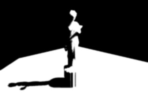
这里,模糊映射图已经完成了,为了增加阴影的模糊程度,增加了纹理上点的采样距离。最后一步自然是将模糊后的纹理图投射回屏幕空间使其显示在屏幕上。
After first Gaussian pass
步骤四:渲染带阴影的场景
为了将模糊后的纹理投射到屏幕上,我们像平常那样渲染场景,但投影模糊后的纹理时要使用屏幕空间的坐标。我们使用裁剪空间的坐标和一些数学方法来产生屏幕空间的坐标。下面的顶点渲染和像素渲染将完成这个工作:
struct VSOUTPUT_SCENE
{
float4 vPosition : POSITION;
float2 vTexCoord : TEXCOORD0;
float4 vProjCoord : TEXCOORD1;
float4 vScreenCoord : TEXCOORD2;
float3 vNormal : TEXCOORD3;
float3 vLightVec : TEXCOORD4;
float3 vEyeVec : TEXCOORD5;
};
// Scene vertex shader
VSOUTPUT_SCENE VS_Scene( float4 inPosition : POSITION,
float3 inNormal : NORMAL,
float2 inTexCoord : TEXCOORD0 )
{
VSOUTPUT_SCENE OUT = (VSOUTPUT_SCENE)0;
// Output the transformed position
OUT.vPosition = mul( inPosition, g_matWorldViewProj );
// Output the texture coordinates
OUT.vTexCoord = inTexCoord;
// Output the projective texture coordinates (we use this
// to project the spot texture down onto the scene)
// 这个是用来产生light map的纹理坐标的。最终效果图中地面上光照效果就是用
// 这个坐标配合上一幅这样的light map实现的。
OUT.vProjCoord = mul( inPosition, g_matTexture );
// Output the screen-space texture coordinates
// 这个就是将裁剪空间的坐标转换到屏幕空间的坐标,方法和将裁剪空间的坐标转换
// 纹理空间的坐标的方法很相似。
OUT.vScreenCoord.x = ( OUT.vPosition.x * 0.5 + OUT.vPosition.w * 0.5 );
OUT.vScreenCoord.y = ( OUT.vPosition.w * 0.5 - OUT.vPosition.y * 0.5 );
OUT.vScreenCoord.z = OUT.vPosition.w;
OUT.vScreenCoord.w = OUT.vPosition.w;
// Get the world space vertex position
float4 vWorldPos = mul( inPosition, g_matWorld );
// Output the world space normal
OUT.vNormal = mul( inNormal, g_matWorldIT );
// Move the light vector into tangent space
OUT.vLightVec = g_vLightPos.xyz - vWorldPos.xyz;
// Move the eye vector into tangent space
OUT.vEyeVec = g_vEyePos.xyz - vWorldPos.xyz;
return OUT;
}
float4 PS_Scene( VSOUTPUT_SCENE IN ) : COLOR0
{
// Normalize the normal, light and eye vectors
IN.vNormal = normalize( IN.vNormal );
IN.vLightVec = normalize( IN.vLightVec );
IN.vEyeVec = normalize( IN.vEyeVec );
// Sample the color and normal maps
float4 vColor = tex2D( ColorSampler, IN.vTexCoord );
// Compute the ambient, diffuse and specular lighting terms
float ambient = 0.0f;
float diffuse = max( dot( IN.vNormal, IN.vLightVec ), 0 );
float specular = pow(max(dot( 2 * dot( IN.vNormal, IN.vLightVec ) * IN.vNormal
- IN.vLightVec, IN.vEyeVec ), 0 ), 8 );
if( diffuse == 0 ) specular = 0;
// Grab the shadow term
float fShadowTerm = tex2Dproj( BlurVSampler, IN.vScreenCoord );
// Grab the spot term
float fSpotTerm = tex2Dproj( SpotSampler, IN.vProjCoord );
// Compute the final color
return (ambient * vColor) +
(diffuse * vColor * g_vLightColor * fShadowTerm * fSpotTerm) +
(specular * vColor * g_vLightColor.a * fShadowTerm * fSpotTerm);
}
终于完成了。看上去不错。该技术的优点一是解决了锯齿问题,二是在多光源,低内存下实现了软阴影。另外该技术与阴影生成方法无关,可以很容易的在shadow volumes技术中采用这项技术。缺点是由于进行了模糊处理而需要一些填充率。
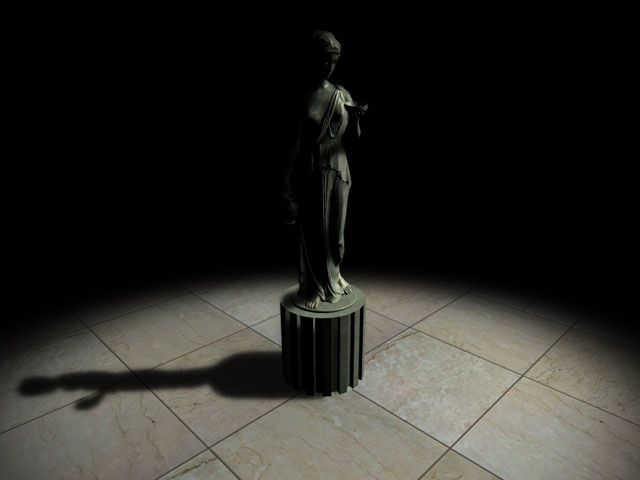
下面是不同阶段的效果比较图:
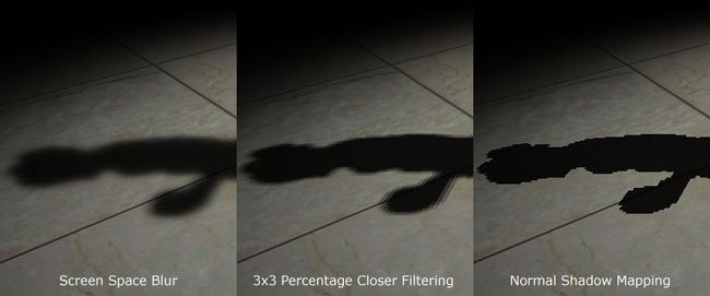
谢谢你阅读这篇文章,如有疑问欢迎来信[email protected]. (这是原作者的信箱)
(汗,好多东西心里明白,但翻译出来就是不满意。各位要是看不明白就找出原文研究吧。)
参考文献
· Hardware Shadow Mapping. Cass Everitt, Ashu Rege and Cem Cebenoyan.
· Hardware-accelerated Rendering of Antialiased Shadows with Shadow Maps. Stefan Brabec and Hans-Peter Seidel.
转载地址:http://bbs.gameres.com/showthread.asp?threadid=36066
图片乃鄙人友情添加,呵呵。
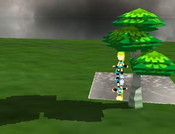
按照上面的方法自己实现了一个:
