【学习笔记】【第五章】仿真验证与Testbench编写
一、Verilog HDL电路仿真和验证概述
仿真,也叫模拟,是通过使用EDA仿真工具,通过输入测试信号,比对输出信号(波形、文本或者VCD文件)和期望值,来确认是否得到与期望所一致的正确的设计结果,验证设计的正确性。验证是一个证明设计思路如何实现,保证设计在功能上正确的一个过程。验证在Verilog HDL设计的整个流程中分为4个阶段:
1、Testbench及其结构
仿真结果:
Verilog HDL测试程序代码:
仿真结果:
仿真,也叫模拟,是通过使用EDA仿真工具,通过输入测试信号,比对输出信号(波形、文本或者VCD文件)和期望值,来确认是否得到与期望所一致的正确的设计结果,验证设计的正确性。验证是一个证明设计思路如何实现,保证设计在功能上正确的一个过程。验证在Verilog HDL设计的整个流程中分为4个阶段:
阶段1: 功能验证——>
阶段2: 综合后验证——>阶段3: 时序验证——>阶段4: 板级验证
1、Testbench及其结构
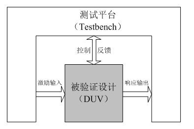
在仿真的时候Testbench用来产生测试激励给待验证设计(Design Under Verification,DUV),或者称为待测设计(Design Under Test,DUT)。
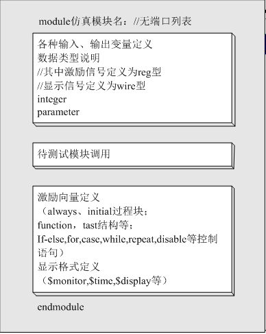
2、测试程序的一般结构
由于Testbench是一个测试平台,信号集成在模块内部,没有输入输出。 在Testbench模块内,例化待测设计的顶层模块,并把测试行为的代码封装在内,直接对待测系统提供测试激励。
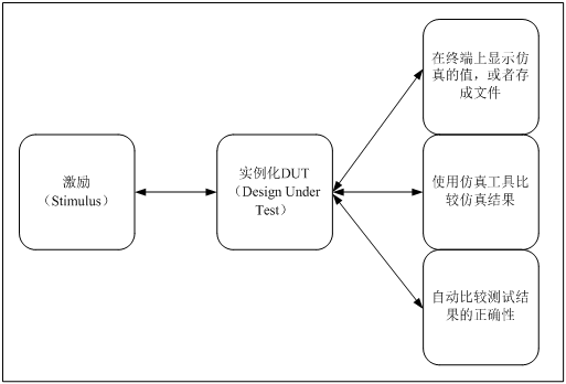
从图中可以清晰地看出Testbench的主要功能:
(1)为DUT提供激励信号。
(2)正确实例化DUT。
(3)将仿真数据显示在终端或者存为文件,也可以显示在波形窗口中以供分析检查。
(4)复杂设计可以使用EDA工具,或者通过用户接口自动比较仿真结果与理想值,实现结果的自动检查。
在编写Testbench时需要注意的问题 :
(1)testbench代码不需要可综合
Testbench代码只是硬件行为描述不是硬件设计 。
(2)行为级描述效率高
Verilog HDL语言具备5个描述层次,分别为开关级、门级、RTL级、算法级和系统级。
(3)掌握结构化、程式化的描述方式
结构化的描述有利于设计维护,可通过initial、always以及assign语句将不同的测试激励划分开来。一般不要将所有的测试都放在一个语句块中。
(1)testbench代码不需要可综合
Testbench代码只是硬件行为描述不是硬件设计 。
(2)行为级描述效率高
Verilog HDL语言具备5个描述层次,分别为开关级、门级、RTL级、算法级和系统级。
(3)掌握结构化、程式化的描述方式
结构化的描述有利于设计维护,可通过initial、always以及assign语句将不同的测试激励划分开来。一般不要将所有的测试都放在一个语句块中。
3、测试平台举例
测试平台需要产生时钟信号、复位信号和一系列的仿真向量,观察DUT的响应,确认仿真结果。
DUT的仿真平台
(1)组合逻辑电路仿真环境的搭建
实例:
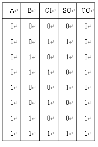
全加器的真值表
Verilog HDL编写的全加器程序代码:
module adder1(a,b,ci,so,co);
    input  a,b,ci;
    output  so,co;
    assign{co,so}=a+b+ci;
endmodule
Verilog HDL测试程序代码:
module adder1_tb;
    wire so,co;
    reg  a,b,ci;
    adder1 U1(a,b,ci,so,co);	//模块例化
    initial               	// 测试信号产生
       begin
              a=0;b=0;ci=0;
           #20 a=0;b=0;ci=1;
           #20 a=0;b=1;ci=0;
           #20 a=0;b=1;ci=1;
           #20 a=1;b=0;ci=0;
           #20 a=1;b=0;ci=1;
           #20 a=1;b=1;ci=0;
           #20 a=1;b=1;ci=1;
           #200  $finish;
       end
   endmodule
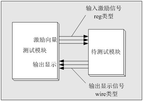
全加器的输入a、b和ci定义为reg型变量;把输出so和co定义为wire型变量用模块例化语句“adder1 U1(a,b,ci,so,co);”把全加器设计电路例化到测试仿真环境中;用initial块语句改变输入的变化并生成测试条件,输入的变化语句完全根据全加器的真值表编写。
仿真结果:
(2)时序逻辑电路仿真环境的搭建
在于时序逻辑电路仿真环境中,需要考虑时序、定时信息和全局复位、置位等信号要求,并定义这些信号。
实例:
Verilog HDL编写的十进制加法计数器源程序代码:
module cnt10(clk,rst,ena,q,cout);
    input   clk,rst,ena;
    output  [3:0]  q;
    output   cout;
    reg    [3:0] q;
    always @ (posedge clk or posedge rst)
       begin
           if(rst)q=4'b0000;
           else if(ena)
              begin
                  if(q<9)q=q+1;
                  else  q=0;
              end
          end
          assign cout=q[3]&q[0];
endmodulemodule cnt10_tb;
reg clk,rst,ena;
wire [3:0] q;
wire cout;
cnt10 U1(clk,rst,ena,q,cout); //模块实例化
always #50 clk=~clk; //时钟信号产生
initial begin
clk=0;rst=0;ena=1; //控制信号产生
#1200 rst=1;
#120 rst=0;
#2000 ena=0;
#200 ena=1;
#20000 $finish;
end
endmodule
实例化语句“cnt10 U1(clk,rst,ena,q,cout);”把十进制计数模块例化到仿真环境中;在always中用语句“#50 clk=~clk;”产生周期为100(标准时间单位)的时钟方波;用initial块生成复位信号rst和使能控制信号ena的测试条件。
仿真结果:
