PIM-DM
涉及知识点:
*PIM DR的选择
*IGMP查询器的选择
*PIM前转器的选择
理论说明:
PIM DR的选择
因为在IGMP V1中不会选举IGMP查询器,如果在同一个多路网段上连接有多台路由器,那么就必须选择PIM DM来避免重复查询!此选举过程由PIM进行,AD越低越优,AD相同再比较metric,同样也是越低越优,还比较不出就将选择IP地址最高的为DR!
IGMP查询器的选择
查询器的选择是针对IGMP V2来说的。网络中拥有最低IP地址的路由器将被选举为IGMP查询器。
PIM前转器的选择
PIM前传器的选择是根据单播路由表条目来的,到组播源的路由的AD最小最优,AD相同就比较metric值,也是最小最优,如果metric值也相同就继续比较IP地址,IP地址则是越大越优!
实验证明:
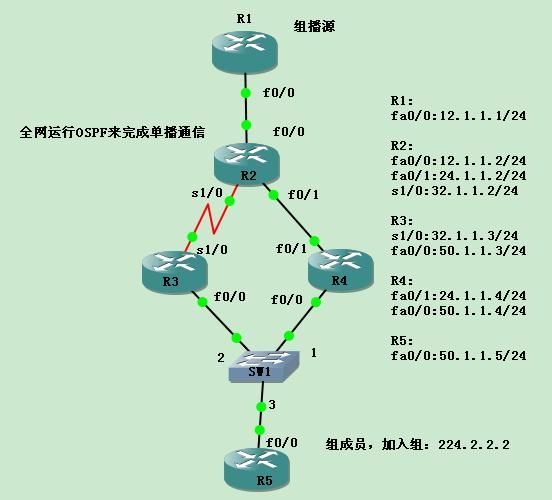
实验基本配置如上图所示!
1 开启组播路由功能
(1)在每台路由器上开启组播路由功能
R1-R5:
R1(config)#ip multicast-routing
2 在接口上开启PIM Dense-Mode
说明:在全网所有路由器的所有接口上开启PIM,从而建立PIM邻居,要在所有接口开启是因为要让PIM自己决定该在什么接口转发组播,这样可以避免RPF检测失败,因为有可能只开部分接口,将导致接口不符合RPF接口而组播失败!
(1)在所有路由器的每个接口上开启PIM
R1(config)#int fa0/0
R1(config-if)#ip pim dense-mode
其他路由器接口同理!
3 查看PIM邻居
说明:相邻的两台路由器接口上开启PIM后,将成为PIM邻居
(1)查看R1的PIM邻居
R1#show ip pim neighbor
PIM Neighbor Table
Mode: B - Bidir Capable, DR - Designated Router, N - Default DR Priority,
S - State Refresh Capable
Neighbor Interface Uptime/Expires Ver DR
Address Prio/Mode
12.1.1.2 FastEthernet0/0 01:56:41/00:01:17 v2 1 / DR S
说明:可以看到R1的PIM邻居有R2,结果正常。因为双方的DR优先级相同,而R2的IP地址大于R1,所以在R1上看到R2为DR。
(2)查看R2的PIM邻居
R2#show ip pim neighbor
PIM Neighbor Table
Mode: B - Bidir Capable, DR - Designated Router, N - Default DR Priority,
S - State Refresh Capable
Neighbor Interface Uptime/Expires Ver DR
Address Prio/Mode
12.1.1.1 FastEthernet0/0 02:02:33/00:01:26 v2 1 / S
24.1.1.4 FastEthernet0/1 02:02:04/00:01:26 v2 1 / DR S
32.1.1.3 Serial1/0 02:02:14/00:01:41 v2 1 / S
(3)查看R3的PIM邻居
R3#show ip pim neighbor
PIM Neighbor Table
Mode: B - Bidir Capable, DR - Designated Router, N - Default DR Priority,
S - State Refresh Capable
Neighbor Interface Uptime/Expires Ver DR
Address Prio/Mode
32.1.1.2 Serial1/0 02:03:13/00:01:42 v2 1 / S
50.1.1.5 FastEthernet0/0 02:02:55/00:01:35 v2 1 / DR S
50.1.1.4 FastEthernet0/0 02:03:00/00:01:34 v2 1 / S
说明:结合R2和R3的输出可以看到DR的选举只在多路网络上才进行选举,R2和R3之前的串口是不选举的,同OSPF上选择DR一样!然后R5地址最大成为DR,R4也成为DR
4 将R5加入组224.2.2.2
说明:组成员要加入组,使用的协议为IGMP,而Cisco路由器开启PIM接口后,接口上将自动开启IGMP,所以R5在加入组时,无需额外开启IGMP而直接加入组224.2.2.2
(1)配置R5加入组224.2.2.2
R5(config)#int fa0/0
R5(config-if)#ip igmp join-group 224.2.2.2
5 测试组播通信
说明:在没有组播数据之前,也就无法确认组播源的位置,在没有组播源的情况下,组播树是不能建立的。在测试R1向组224.2.2.2发送组播流量时,只需要Ping224.2.2.2,只要数据包的目标地址为组播地址,就自动使用组播方式来传递。在R1上Ping组播,那么R1就是组播源
(1)从组播源R1上ping 224.2.2.2
R1#ping 224.2.2.2
Type escape sequence to abort.
Sending 1, 100-byte ICMP Echos to 224.2.2.2, timeout is 2 seconds:
Reply to request 0 from 50.1.1.5, 600 ms
说明:从回包中看出,已经收到组成员50.1.1.5的回包,说明组播成功被转发到组成员R5
6 查看IGMP查询器
(1)在R5上查看网络中的IGMP查询器
R5#show ip igmp interface fa0/0
FastEthernet0/0 is up, line protocol is up
Internet address is 50.1.1.5/24
IGMP is enabled on interface
Current IGMP host version is 2
Current IGMP router version is 2
IGMP query interval is 60 seconds
IGMP querier timeout is 120 seconds
IGMP max query response time is 10 seconds
Last member query count is 2
Last member query response interval is 1000 ms
Inbound IGMP access group is not set
IGMP activity: 2 joins, 0 leaves
Multicast routing is enabled on interface
Multicast TTL threshold is 0
Multicast designated router (DR) is 50.1.1.5 (this system)
IGMP querying router is 50.1.1.3
Multicast groups joined by this system (number of users):
224.0.1.40(1) 224.2.2.2(1)
说明:与前面理论描述的一致,IP地址小的被设置为IGMP查询器!此处R3的地址为50.1.1.3,小于R4的50.1.1.4!
(2)改大R3fa0/0的接口地址为50.1.1.10,再看IGMP查询器是否改变为50.1.1.4
R3(config)#int fa0/0
R3(config-if)#ip ad 50.1.1.10 255.255.255.0
R5#show ip igmp interface fa0/0
FastEthernet0/0 is up, line protocol is up
Internet address is 50.1.1.5/24
IGMP is enabled on interface
Current IGMP host version is 2
Current IGMP router version is 2
IGMP query interval is 60 seconds
IGMP querier timeout is 120 seconds
IGMP max query response time is 10 seconds
Last member query count is 2
Last member query response interval is 1000 ms
Inbound IGMP access group is not set
IGMP activity: 2 joins, 0 leaves
Multicast routing is enabled on interface
Multicast TTL threshold is 0
Multicast designated router (DR) is 50.1.1.10
IGMP querying router is 50.1.1.4
Multicast groups joined by this system (number of users):
224.0.1.40(1) 224.2.2.2(1)
说明:可以看到IGMP查询器已经变为50.1.1.4,进一步证明了上面的理论!注意如果看不到现象就刷新下OSPF进程
7 查看PIM前传器
(1)把见面的IGMP查询地址恢复成原来的,再查看R3和R4到组播源的单播路由表
R3#show ip route
Gateway of last resort is not set
50.0.0.0/24 is subnetted, 1 subnets
C 50.1.1.0 is directly connected, FastEthernet0/0
32.0.0.0/24 is subnetted, 1 subnets
C 32.1.1.0 is directly connected, Serial1/0
24.0.0.0/24 is subnetted, 1 subnets
O 24.1.1.0 [110/2] via 50.1.1.4, 00:00:11, FastEthernet0/0
12.0.0.0/24 is subnetted, 1 subnets
O 12.1.1.0 [110/3] via 50.1.1.4, 00:00:11, FastEthernet0/0
R4#show ip route
Gateway of last resort is not set
50.0.0.0/24 is subnetted, 1 subnets
C 50.1.1.0 is directly connected, FastEthernet0/0
32.0.0.0/24 is subnetted, 1 subnets
O 32.1.1.0 [110/65] via 50.1.1.3, 00:00:32, FastEthernet0/0
[110/65] via 24.1.1.2, 00:00:32, FastEthernet0/1
24.0.0.0/24 is subnetted, 1 subnets
C 24.1.1.0 is directly connected, FastEthernet0/1
12.0.0.0/24 is subnetted, 1 subnets
O 12.1.1.0 [110/2] via 24.1.1.2, 00:00:32, FastEthernet0/1
说明:可以看到AD相同,R4到组播源的metric为2,R3为3,所以R4将被选为PIM前传器,最后结果将在R2组播路由表中体现出来
(2)查看R2的组播路由表
R2#show ip mroute
IP Multicast Routing Table
Flags: D - Dense, S - Sparse, B - Bidir Group, s - SSM Group, C - Connected,
L - Local, P - Pruned, R - RP-bit set, F - Register flag,
T - SPT-bit set, J - Join SPT, M - MSDP created entry,
X - Proxy Join Timer Running, A - Candidate for MSDP Advertisement,
U - URD, I - Received Source Specific Host Report,
Z - Multicast Tunnel, z - MDT-data group sender,
Y - Joined MDT-data group, y - Sending to MDT-data group
Outgoing interface flags: H - Hardware switched, A - Assert winner
Timers: Uptime/Expires
Interface state: Interface, Next-Hop or VCD, State/Mode
(*, 224.2.2.2), 00:00:06/stopped, RP 0.0.0.0, flags: D
Incoming interface: Null, RPF nbr 0.0.0.0
Outgoing interface list:
Serial1/0, Forward/Dense, 00:00:06/00:00:00
FastEthernet0/1, Forward/Dense, 00:00:06/00:00:00
FastEthernet0/0, Forward/Dense, 00:00:06/00:00:00
(12.1.1.1, 224.2.2.2), 00:00:06/00:02:56, flags: T
Incoming interface: FastEthernet0/0, RPF nbr 0.0.0.0
Outgoing interface list:
FastEthernet0/1, Forward/Dense, 00:00:08/00:00:00
Serial1/0, Prune/Dense, 00:00:08/00:02:54, A
(*, 224.0.1.40), 02:33:09/00:02:57, RP 0.0.0.0, flags: DCL
Incoming interface: Null, RPF nbr 0.0.0.0
Outgoing interface list:
FastEthernet0/1, Forward/Dense, 02:32:40/00:00:00
Serial1/0, Forward/Dense, 02:32:51/00:00:00
FastEthernet0/0, Forward/Dense, 02:33:09/00:00:00
说明1:可以看到在(12.1.1.1,24.2.2.2)条目的出口上,fa0/1为转发状态,s1/0为修剪状态,所以R4被选为了PIM前传器,这就证明了前面的理论!
说明2:在PIM-DM模式中同样也有(*,G)的记录,创建(*,G)是为了作为(S,G)的“父”数据结构
8 改变PIM的前传器
说明:根据前面的理论,要想改变PIM的前传器,在相同AD下只需要改变其metric值,这里我们先把其metric也设为一样,再改变R3fa0/0的地址为50.1.1.10
(1)改变R3接口s0/0的cost值,并查看R3到组播源R1的metric
R3(config)#int s1/0
R3(config-if)#ip ospf cost 1
R3#show ip route
Gateway of last resort is not set
50.0.0.0/24 is subnetted, 1 subnets
C 50.1.1.0 is directly connected, FastEthernet0/0
32.0.0.0/24 is subnetted, 1 subnets
C 32.1.1.0 is directly connected, Serial1/0
24.0.0.0/24 is subnetted, 1 subnets
O 24.1.1.0 [110/2] via 50.1.1.4, 00:00:11, FastEthernet0/0
[110/2] via 32.1.1.2, 00:00:11, Serial1/0
12.0.0.0/24 is subnetted, 1 subnets
O 12.1.1.0 [110/2] via 32.1.1.2, 00:00:11, Serial1/0
说明:可以看到metric改为和R4一样了,都为2!
(2)在R2查看PIM前传器结果
R2#show ip mroute
(12.1.1.1, 224.2.2.2), 00:00:04/00:02:55, flags: T
Incoming interface: FastEthernet0/0, RPF nbr 0.0.0.0
Outgoing interface list:
FastEthernet0/1, Forward/Dense, 00:00:06/00:00:00
Serial1/0, Prune/Dense, 00:00:05/00:02:54
说明:可以看到结果任然没有改变,虽然R3到组播源的metric和R4一样了,但是R4的IP地址任然大于R3!
(3)改变R3的IP地址为50.1.1.10,并查看前传器结果
R3(config)#int fa0/0
R3(config-if)#ip ad 50.1.1.10 255.255.255.0
R2#show ip mroute
(12.1.1.1, 224.2.2.2), 00:00:04/00:02:55, flags: T
Incoming interface: FastEthernet0/0, RPF nbr 0.0.0.0
Outgoing interface list:
FastEthernet0/1, Prune/Dense, 00:00:05/00:02:54
Serial1/0, Forward/Dense, 00:00:05/00:00:00
说明:可以看到前传器已经改变!至此,前面的理论已经证明完毕!
补充PIM-DM知识点
1 如果一个路由器有5个接口,其中一个为组播源接口,一个连接了组成员接口,在PIM DM中,这些没有连接组成员的接口也为被放在出口中,也就是说出口记录了4个,实际上只用了1个,这样有点浪费资源了!还是上面的实验,我们查看R2的组播路由表:
R2#show ip mroute
(12.1.1.1, 224.2.2.2), 00:00:04/00:02:55, flags: T
Incoming interface: FastEthernet0/0, RPF nbr 0.0.0.0
Outgoing interface list:
FastEthernet0/1, Prune/Dense, 00:00:05/00:02:54
Serial1/0, Forward/Dense, 00:00:05/00:00:00
说明:可以看到被修剪的接口依然放在了出口,如果是PIM-SM就不会!
