计算图是TensorFlow领域模型的核心。本文通过对计算图领域模型的梳理,讲述计算图构造的基本原理。
边
Edge持有前驱节点与后驱节点,从而实现了计算图的连接,也是计算图前向遍历,后向遍历的衔接点。
边上的数据以Tensor的形式传递,Tensor的标识由源节点的名称,及其所在边的src_output唯一确定。也就是说,tensor_id = op_name:src_output
src_output与dst_input
Edge持有两个重要的属性:
-
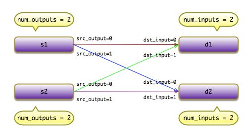
src_output:表示该边为前驱节点的第src_output条输出边; -
dst_input:表示该边为后驱节点的第dst_input条输入边。
例如,存在两个前驱节点s1, s2,都存在两条输出边;存在两个后驱节点d1, d2,都存在两条输入边。
控制依赖
计算图中存在两类边,
- 普通边:用于承载Tensor,常用实线表示;
- 控制依赖:控制节点的执行顺序,常用虚线表示。
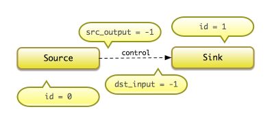
特殊地,控制依赖边,其src_output, dst_input都为-1(Graph::kControlSlot),暗喻控制依赖边不承载任何数据,仅仅表示计算的依赖关系。
bool Edge::IsControlEdge() const {
   return src_output_ == Graph::kControlSlot;
}
节点
Node(节点)持有零条或多条输入/输出的边,分别使用in_edges, out_edges表示。另外,Node持有NodeDef, OpDef。其中,NodeDef持有设备分配信息,及其OP的属性值集合;OpDef持有OP的元数据。
输入边
在输入边的集合中按照索引线性查找,当节点输入的边比较多时,可能会成为性能的瓶颈。依次类推,按照索引查找输出边,算法相同。
Status Node::input_edge(int idx, const Edge** e) const {
  for (auto edge : in_edges()) {
    if (edge->dst_input() == idx) {
      *e = edge;
      return Status::OK();
    }
  }
  return errors::NotFound("not found input edge ", idx);
}
前驱节点
首先通过idx索引找到输入边,然后通过输入边找到前驱节点。依次类推,按照索引查找后驱节点,算法相同。
Status Node::input_node(int idx, const Node** n) const {
  const Edge* e;
  TF_RETURN_IF_ERROR(input_edge(idx, &e));
  if (e == nullptr) {
    *n = nullptr;
  } else {
    *n = e->src();
  }
  return Status::OK();
}
图
Graph(计算图)就是节点与边的集合,领域模型何其简单。计算图是一个DAG图,计算图的执行过程将按照DAG的拓扑排序,依次启动OP的运算。其中,如果存在多个入度为0的节点,TensorFlow运行时可以实现并发,同时执行多个OP的运算,提高执行效率。
空图
计算图的初始状态,并非是一个空图。实现添加了两个特殊的节点:Source与Sink节点,分别表示DAG图的起始节点与终止节点。其中,Source的id为0,Sink的id为1;依次论断,普通OP节点的id将大于1。
另外,Source与Sink之间,通过连接「控制依赖」的边,保证计算图的执行始于Source节点,终于Sink节点。它们之前连接的控制依赖边,其src_output, dst_input值都为-1。
习惯上,仅包含Source与Sink节点的计算图也常常称为空图。
Node* Graph::AddEndpoint(const char* name, int id) {
  NodeDef def;
  def.set_name(name);
  def.set_op("NoOp");

  Status status;
  Node* node = AddNode(def, &status);
  TF_CHECK_OK(status);
  CHECK_EQ(node->id(), node_id);
  return node;
}

Graph::Graph(const OpRegistryInterface* ops)
    : ops_(ops), arena_(8 << 10 /* 8kB */) {
  auto src  = AddEndpoint("_SOURCE", kSourceId);
  auto sink = AddEndpoint("_SINK",   kSinkId);
  AddControlEdge(src, sink);
}
非空图
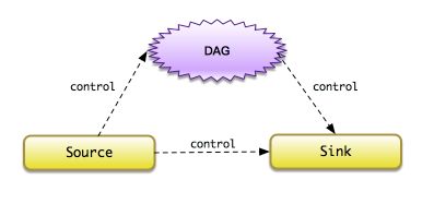
在前端,用户使用OP构造器,将构造任意复杂度的计算图。对于运行时,无非就是将用户构造的计算图通过控制依赖的边与Source/Sink节点连接,保证计算图执行始于Source节点,终于Sink节点。
添加边
计算图的构造过程非常简单,首先通过Graph::AddNode在图中放置节点,然后再通过Graph::AddEdge在图中放置边,实现节点之间的连接。
const Edge* Graph::AllocEdge() const {
  Edge* e = nullptr;
  if (free_edges_.empty()) {
    e = new (arena_.Alloc(sizeof(Edge))) Edge;
  } else {
    e = free_edges_.back();
    free_edges_.pop_back();
  }
  e->id_ = edges_.size();
  return e;
}

const Edge* Graph::AddEdge(Node* source, int x, Node* dest, int y) {
  auto e = AllocEdge();
  e->src_ = source;
  e->dst_ = dest;
  e->src_output_ = x;
  e->dst_input_ = y;

  CHECK(source->out_edges_.insert(e).second);
  CHECK(dest->in_edges_.insert(e).second);

  edges_.push_back(e);
  edge_set_.insert(e);
  return e;
}
添加控制依赖边,则可以转发调用Graph::AddEdge实现。
const Edge* Graph::AddControlEdge(Node* src, Node* dst) {
  return AddEdge(src, kControlSlot, dst, kControlSlot);
}
开源技术书
- TensorFlow内核剖析
- 源代码
https://github.com/horance-liu/tensorflow-internals


