问题的背景
- 关于数据包类型
When communicating in an asynchronous connection link (“ACL”) data connection, the devices 102, 104 utilize “DM” and “DH” packets. A “DM” packet refers to a medium data rate packet, and a “DH” packet refers to a high data rate packet. DM and DH packets have a suffix that refers to the number of time “slots” the particular packet spans. In other words, DM and DH packets have a suffix that refers to the number of time “slots” required to transmit the packet. For example, a DM1 packet is transmitted in one time slot, and a DH3 packet is transmitted in three time slots.
The packet data rate and the number of time slots the packet spans determine the amount of information the packet carries, that is, the packet's data payload. For example, a DM1 packet, which spans one time slot, carries 18 bytes of information, while a DM3 packet, which spans three time slots, carries 123 bytes of information. Further, the longer a packet remains at a particular frequency bin (the more time slots a packet spans), the more susceptible the packet is to interference from another signal at that frequency bin. Thus, a DM3 packet, which spans three time slots, is more susceptible to interference than a DM1 packet, which only spans one time slot.
DM packets have forward error correction (“FEC”), which is an error protection scheme designed to reduce the number of re-transmissions required to successfully communicate a packet's data payload between transmitting and receiving Bluetooth devices. FEC error protection is useful to communicate a packet's data payload from a transmitting Bluetooth device to a receiving Bluetooth device in an environment where an undesirable level of interference exists. However, in an environment containing a minimal level of interference, the FEC error protection scheme adds unnecessary overhead that reduces data throughput.
DM packets utilize a “⅔ rate” FEC protection scheme, which encodes each block of 10 information bits into a 15 bit codeword. This code can correct all single errors and detect all double errors in each codeword. In contrast to DM packets, which utilize ⅔ rate FEC error protection, DH packets provide no FEC error protection. Thus, for example, DH packets are appropriate for use in a relatively error-free environment where high data throughput is desired, whereas DM packets are more appropriate to reduce the number of retransmissions in an error-producing environment, that is, an environment containing a high level of interference.
要解决的问题
In addition to Bluetooth devices, the ISM band is also occupied by systems that operate under the IEEE 802.11 b specification for wireless local area networks (“IEEE 802.1lb wireless systems”). Other devices such as microwave ovens also operate in the same ISM band. IEEE 802.1 lb wireless systems and microwave ovens operate in the ISM band at much greater transmit power than Bluetooth devices. Thus, due to the overlapping frequency bands and greater signal strength utilized by some non-Bluetooth devices, there is a possibility of such devices interfering with Bluetooth communications.
Signal interference is undesirable for various reasons. Chiefly, signal interference can cause Bluetooth transmissions to fail, requiring time-consuming retransmission at the expense of additional power consumption. Since many Bluetooth devices operate on battery power, greater power consumption is undesirable because it drains the battery more quickly. Ultimately, the battery must be recharged, or if a recharging source is unavailable, the battery will cease to operate. As another disadvantage of signal interference, retransmission of Bluetooth signals increases the possibility of causing interference for other Bluetooth and/or IEEE 802.11 b wireless systems operating in the same area. As still another disadvantage, signal interference can reduce the quality of real-time, streaming data, causing a garbled or low quality signal. For various reasons, then, signal interference in Bluetooth communications is undesirable.
To avoid interference from other devices operating in the ISM band, the Bluetooth system uses a technique known as “frequency hop spread spectrum.” In frequency hop spread spectrum, inter-communicating Bluetooth devices hop to a different frequency after each transmission and reception, at a rate of 1600 hops per second. Thus, transmitting and receiving at a different frequency 1600 times per second reduces the probability of the Bluetooth devices encountering long lasting signal interference in one particular frequency bin.
The following approach has been developed to further reduce potential interference to Bluetooth communications. Here, the Bluetooth devices identify the particular ISM frequency bins where interfering devices are radiating or transmitting. The inter-communicating Bluetooth devices then agree to avoid transmitting and receiving on those particular bin frequencies. However, this approach requires governmental approval from the Federal Communications Commission, which currently does not allow devices operating in the ISM band to coordinate transmissions of two radios by selecting fixed frequency subsets.
Another approach is mentioned in a white paper published by Texas Instruments, entitled “Wi-Fi (IEEE 802.1 lb) and Bluetooth,” by Matthew B. Shoemaker, February 2001, Version 1.1. The Shoemaker paper recognizes that various mechanisms can be used to improve the coexistence level of Bluetooth devices when interference is present. For data connections, Shoemaker proposes that Bluetooth devices adaptively select the type of error control used and the length of each packet to transmit in order to maximize the throughput. In addition, Shoemaker proposes flow control to dynamically increase and decrease the rate of transmission. For example, when a contiguous block of bad channels is reached, the Bluetooth device places traffic on hold until good channels are available. Nonetheless, the Shoemaker paper lacks practical details of how to implement these concepts.
Consequently, known Bluetooth communication systems are not completely adequate in all respects due to the unsolved problem of signal interference.
解决方案细节
- 发射和接收机模块
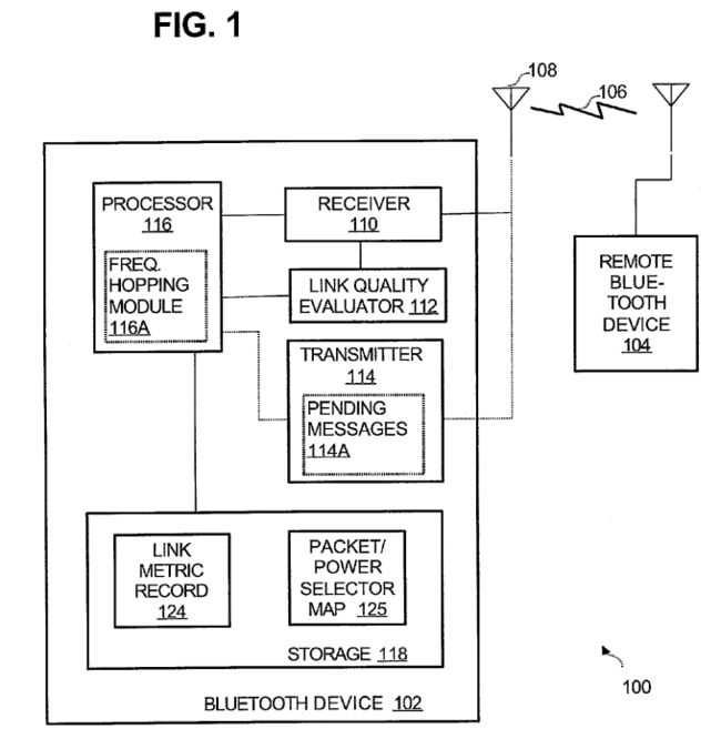
The transmitter 114 is configured to transmit Bluetooth messages in the form of voice and/or data packets to devices such as the remote device 104, using the antenna 108 and wireless link 106. The transmitter 114 is illustrated with messages 114a pending transmission to the remote device 104. The pending messages 114a may be implemented in a buffer, register, or other storage. Alternatively, the messages 114a may be located in storage of the processor 116 or another location, the illustrated location 114a being shown as one example.
Link quality evaluator 112 comprises circuitry to evaluate the quality of signals received by 110. In the illustrated example, the evaluator 112 measures quality of signals arriving in any of the 80 frequency bins in the 2.4 GHz ISM band. Signal quality may be gauged by measured energy (total strength of received signals), the number of packets of a received message in error (“packet error rate”), the signal-to-noise ratio, number of messages whose receipt is failed requiring retransmission by the remote device 104, or another appropriate criteria. One particular gauge of measured energy is received signal strength indicator (RSSI). Depending upon the nature of the signal evaluation being implemented, the evaluator 112 may be coupled to the receiver 110, processor 116, or both. In the illustrated example, the invention 112 keeps track of signal strength of received signals (whether noise or not), keeps track of signal strength of bona fide Bluetooth signals, and also identifies and tracks signal interference levels.
- 链路质量度量表
The storage 118 includes a link metric record 124 and a packet/power selector map 125. The record 124 is used to store information produced by the evaluator 112, and namely, information evaluating the signal quality in the various Bluetooth communication frequencies.
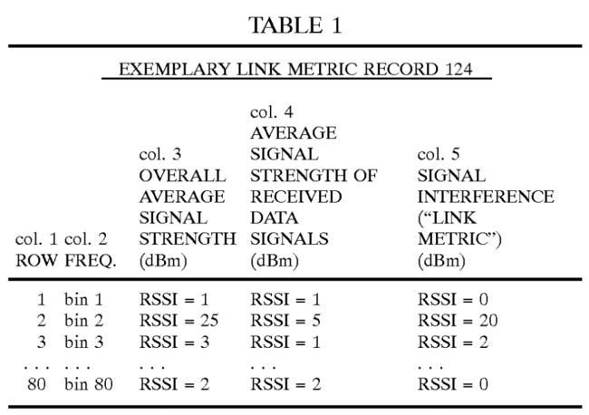
In one specific implementation, the record 124 comprises a table as shown below in TABLE 1. The illustrated table includes 80 rows, with each row corresponding to one of the 80 frequency bins in the 2.4 GHz ISM band. For each frequency bin, the record 124 lists the evaluator 112's overall rating of average signal strength for this bin (for both data and noise), the average signal strength of data-only signals in this frequency bin, and the average signal interference (namely the difference between overall and data signal strength). Optionally, signal interference (column 5) may be omitted to conserve storage, since this information may be obtained by taking the difference of columns 2 and 3. The particular example of TABLE 1 utilizes RSSI to measure signal quality. In the example of TABLE 1, then, frequency bin 2 shows a significant amount of noise since the overall average RSSI is 25 but the average of received data signals is 5. In contrast, frequency bin 1 shows no noise as the overall average and data-only average signal strengths are the same.
- 数据包和发射功率映射表
The storage 118 further includes a packet/power selector map 125. The map 125 contains instructions, data, logic, artificial intelligence, or other data or decision making capability to determine which packet type is appropriate to transmit pending messages 114a. This decision is based upon the size of the message 114a, frequency bin to be used (according to the Bluetooth frequency hopping scheme), signal interference in that frequency bin (according to the record 124), characteristics inherent to each different packet type (e.g., number of slots, robustness of error correction, etc.), and the like. The map 125 also contains data or decision making capability to determine which power level is appropriate to transmit pending messages 114a, based on the foregoing considerations and, in addition, the type of packet to be used. The map 125, also referred to as “mapping rules,” may be implemented by a lookup table, relational or non-relational database, logic circuitry, instruction processing machine, artificial intelligence, or other appropriate decision maker. TABLE 2, below, gives one example of some exemplary entries in a packet/power selector map 125, implemented as a lookup table.
- 更多考虑
TABLE 2 is configured to determine the optimal packet type and transmit power level for each particular circumstance. The “optimal” packet type and transmit power is that which is most likely to maintain data throughput while producing a minimal level of packet re-transmissions at a particular frequency bin, and takes into account, for example, the advantages and properties of packet types as discussed above.
Some exemplary considerations are discussed in greater detail as follows. One consideration includes the limitations of the equipment. For instance, one known model of transmitter 114 is capable of operating at a range of −60.0 dBm to 0 dBm, that is, one microwatt to approximately one milliwatt. In this embodiment, the typical power level for transmitting packets may be between −35.0 dBm to −40.0 dBm. Other considerations include the competing concerns of more robust error correction (versus slower communication), shorter data packets (versus slower communication), longer data packets (versus greater exposure to signal interference), more transmit power (versus shorter battery length), and the like. As an example, one consideration of competing concerns recognizes that if signal interference is significantly high (indicating poorer channel conditions), then TABLE 2 should specify a more reliable (less error prone) packet type. For example, a DM1 packet, which has ⅔ rate FEC protection and spans only one time slot, is more reliable than a DH3 packet, which has no FEC protection and spans three time slots. In a different example, TABLE 2 may specify an upper limit on packet size for each set of conditions, leaving the processor 116 free to choose that or any smaller packet size depending upon the circumstances.
- 测量信号干扰的流程图
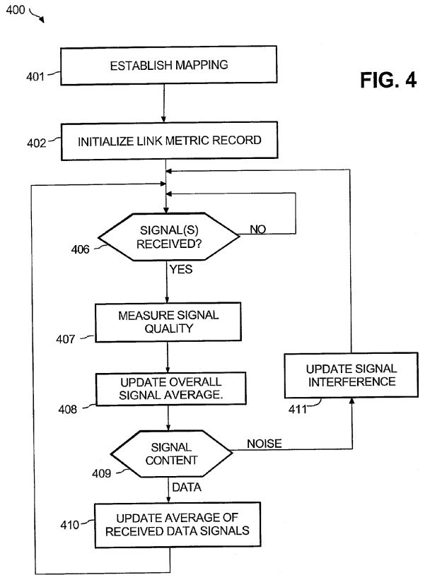
Referring FIG. 4, the sequence 400 describes an exemplary process for evaluating received Bluetooth signals to measure signal interference. As described below in FIG. 5, this information is used to optimize Bluetooth transmissions to succeed in spite of signal interference. For illustrative purposes, without any intended limitation, the sequence 400 is described in the context of the Bluetooth device 102 in its communication with the remote device 104 (FIG. 1).
In step 401, the map 125 is established. This step may be performed in different ways, depending upon the structure of the map 125. For instance, step 401 may involve programmers, engineers, technicians, or other designers constructing a lookup table, configuring logic circuitry, training an artificial intelligence unit, or otherwise configuring the map 125. In this step, the map 125 is configured to choose the packet type and power level appropriate to transmit messages 114a and maintain data throughput while producing a minimal level of packet re-transmissions for each particular frequency bin. The map 125 provides mapping rules correlating different packet types to be used for transmission with various conditions including, at minimum, measured signal interference characteristics. A few examples follow.
In one example, if the most recent update of frequency bin 4 indicated a link metric value of 5, and the amount of data to be transmitted is 25 bytes, then a DH1 packet is chosen with transmit power level of −12 dBm (as shown by row 3 of TABLE 2, above). In another example, if the most recent update of frequency bin 6 indicated a link metric of 15, and the amount of data to be transmitted is 23 bytes, then a DM1 is selected with transmit power of 0 dBm (as shown by row 5 of TABLE 2, above). The remainder 6 bytes is transmitted in the next slot. In still another example, if the most recent update of frequency bin 8 indicated a link metric of 14, and 112 bytes of data are to be transmitted, then a DM3 packet is selected and the transmit power level is set to −5 dBm (as shown by row 7 of TABLE 2, above).
In step 402, the processor 116 initializes the link metric record 124. For instance, the processor 116 may open a blank table, clear a previously established table, create a data structure, or otherwise initialize a data object appropriate to the record 124.
In step 406, the processor 116 and/or receiver 110 determines whether the device 102 has received any signals from other Bluetooth devices. This may be achieved, for example, by checking a receive buffer (not shown), polling the receiver 110, checking a record of past signals that have already been received but not evaluated for signal interference, or another technique. If there are any received signals that have not been evaluated (as discussed below), the process 400 advances from step 406 to step 407, where the link quality evaluator 112 selects the next received signal (by time of receipt, priority, frequency bin, or any other selection criteria) and then measures the received signal's quality. As mentioned above, the evaluator 112 may gauge signal quality based on measured energy (total strength of received signals, such as RSSI), the number of packets of a received message in error (“packet error rate”), the signal-to-noise ratio, number of messages whose receipt is failed requiring retransmission by the remote device 104, or another appropriate criteria. The evaluator 112 operates using information from the receiver 110 or the processor 116, depending upon the nature of the signal evaluation. For instance, signal-to-noise ratio may be determined based on information from the receiver 110, whereas packet error information is available from the processor 116.
After step 407, the processor 116 in step 408 updates the record 124's overall average signal strength (column 3, TABLE 1). Then, based on the measurement of step 407, step 409 then determines whether the current received signal represents data from another Bluetooth device or signal interference. Broadly, step 409 compares measured signal quality of the received signal against a longstanding average for that characteristic. If the current signal exhibits a sudden deviation from the norm, a conclusion of signal interference is made, and step 409 advances to step 411 to update the signal interference shown in the record 124, namely, the difference between the average overall signal strength (updated in step 408) and the standing average data signal strength. Otherwise, if step 409 finds that the evaluated signal represents data, step 409 advances to step 410, where the processor 116 updates the data-only signal strength. For instance, if the record 124 maintains a running average of RSSI for data signals (as in column 4, TABLE 1), the processor 116 updates the average shown in the record 124 to include the current signal strength. After step 410, step 411 is performed to update the signal interference shown in the record 124, namely, the difference between the average overall signal strength (updated in step 408) and the average data signal strength (updated in step 410). After step 411, the routine 400 returns to step 406 to check for other received signals to process.
As a more particular example of step 409, the link evaluator 112 may compare the received signal's RSSI to the long term average for received data signals (e.g., from column 3, TABLE 1). This average may be constituted of received signals from a recent time window, for received signals of the same frequency bin, or another group of received signals. If the current RSSI exceeds the norm by 5 dBm, 10 dBm, or another prescribed amount, then the link evaluator 112 in step 409 concludes that the current signal is interference rather than Bluetooth data. In another example, the link evaluator 112 may maintain a longstanding average packet error rate (such as CRC failure). If the current signal's CRC failure exceeds the norm by a prescribed margin, the link evaluator 112 in step 409 concludes that the current signal is interference rather than Bluetooth data.
- 优化蓝牙发射机以克服信号干扰的流程图
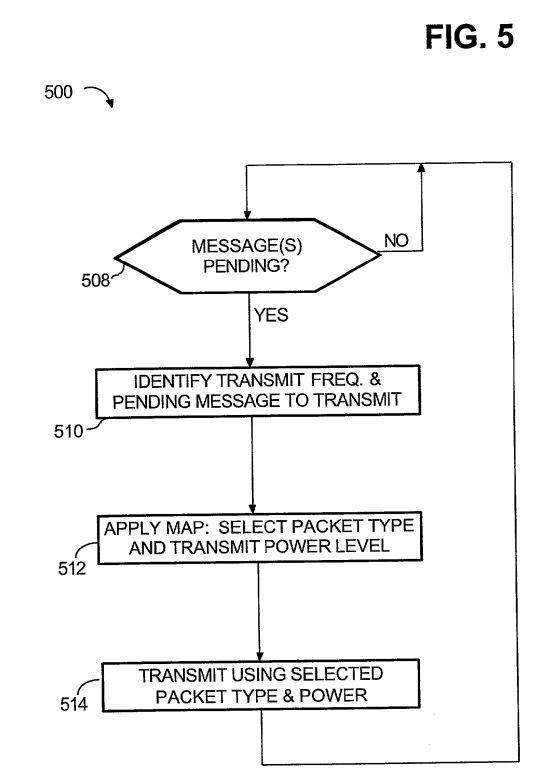
Referring FIG. 5, the sequence 500 describes an exemplary process for optimizing Bluetooth transmissions to overcome signal interference, utilizing the link metric record 124 prepared in the sequence 400. For illustrative purposes, without any intended limitation, the sequence 500 is described in the context of the Bluetooth device 102 in its communication with the remote device 104 (FIG. 1).
In step 508, the processor 116 and/or transmitter 114 determines whether there are any messages pending transmission to remote devices such as 104. In the illustrated embodiment, this is achieved by checking the pending messages 114a. If there are any pending transmit messages, step 510 is performed, where the processor 116 identifies the next message 114a to be transmitted to the remote device 104. This is referred to as the “next pending message.” Also in step 510, the processor 116 receives information from the frequency hopping module 116a designating the next frequency bin to be used in transmitting the next pending message 114a to the remote device 104.
In step 512, the processor 116 chooses the packet type and power level to be used in transmitting the next pending message 114a that was identified in step 510. More particularly, the processor 116 applies the map 125 to the historical signal interference associated with the frequency bin that was selected in step 510. The historical signal interference is obtained from the record 124, as prepared earlier in step 407. For instance, signal interference in the illustrated TABLE 1 is the difference between the average overall signal strength and the average data-only signal strength.
Step 512 determines which packet type(s) to use in transmitting the next pending message to the remote Bluetooth device 104. Depending upon contents of the map 125, the processor 116 may also apply the map 125 to any other applicable properties of the next pending message, assessed signal interference, or other conditions; one example of an additional condition is the size of the message to be sent. As another component of step 512, the processor 116 selects the transmit power level by applying the map 125 to the assessed signal interference characteristics, designated frequency of the module 116a, selected data packet type, and any other relevant properties specified in the map 125.
In a different embodiment of step 512, the map 125 may specify that the processor 116 utilizes a conventional Bluetooth packet/power selection routine as long as the signal interference indicated by the record 124 exceeds does not exceed a predetermined threshold, otherwise utilizing the conventional Bluetooth packet/power selection routine within certain limits if signal interference does exceed the threshold. For instance, the map 125 may dictate that if signal interference exceeds a threshold of −25.0 dBm for frequency bin 30, then future transmissions using that frequency bin 30 must be limited to DM1, DM3, or DH1 packet types. In this example, different thresholds may be used for different frequency bins, or one universal threshold may be applied to all frequency bins. Moreover, different upper limits on packet types may be set for different frequency bins, or one universal data packet limit set.
Next after step 512, the processor 116 in step 514 directs the transmitter 114 to transmit the next pending message 114 using the data packet type and transmit power level chosen in step 512. Following step 514, the program 500 returns to step 508 to process another message pending transmission.
对该方案的总结
原来数据包类型和时隙的选择还有这么多可以考虑。


