Unity Shader - ddx/ddy偏导函数测试,实现:锐化、高度图、Flat shading应用
这两条指令用于对指定的寄存器,求其值在临近像素上的变化率,因为纹理坐标的梯度可以用来确定纹理当前被缩放的程度,可用该值来计算Mip层,另外它也可以用来计算Texel的跨越Size,由此求得正确的过滤宽度,从而纠正通常的线性过滤在远处由于过滤宽度错误而产生的失真。
参考:hlsl函数 ddx ddy
HLSL叫:HLSL ddx、HLSL ddy
ddx(x), ddy(y)
// 其中x,y都是screen space x,y
GLSL叫:
dFdx(x), dFdy(y)
看一个GLSL的图解,用在纹理采样中,此图出自:An introduction to shader derivative functions,这篇文章也是介绍偏导函数的
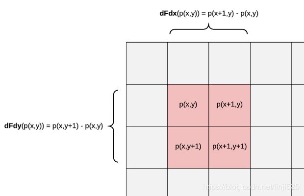
要注意的是,不论HLSL还是GLSL中,偏导函数都只能在fragment shader阶段处理
可用它来做什么
简单的边缘突出应用
在下面Project提供的源Unity工程的 Sharpen.unity 场景
Shader
// jave.lin 2019.07.02
Shader "Test/TestDDX&Tex"
{
    Properties
    {
        [KeywordEnum(IncreaseEdgeAdj, BrightEdgeAdj)] _EADJ("Edge Adj type", Float) = 0
        _Tex("Tex", 2D) = "white" {}
        _Intensity("Intensity", Range(0, 20)) = 2
    }
    SubShader
    {
        Pass
        {
            Tags { "RenderType"="Opaque" }
            Cull off
            Blend SrcAlpha OneMinusSrcAlpha

            CGPROGRAM
            #pragma vertex vert
            #pragma fragment frag
            #pragma multi_compile _EADJ_INCREASEEDGEADJ _EADJ_BRIGHTEDGEADJ
            #include "UnityCG.cginc"
            struct appdata
            {
                float4 vertex : POSITION;
                float2 uv : TEXCOORD0;
            };
            struct v2f
            {
                float2 uv : TEXCOORD0;
                float4 vertex : SV_POSITION;
            };
            sampler2D _Tex;
            float4 _Tex_ST;
            float _Intensity;
            v2f vert (appdata v)
            {
                v2f o;
                o.vertex = UnityObjectToClipPos(v.vertex);
                o.uv = TRANSFORM_TEX(v.uv, _Tex);
                return o;
            }
            fixed4 frag (v2f i, float f : VFACE) : SV_Target
            {
                fixed a = 1;
                if (f < 0) a = 0.5;
                fixed3 c = tex2D(_Tex, i.uv).rgb;
                #if _EADJ_INCREASEEDGEADJ // 边缘调整:增加边缘差异调整
                // 类似两个3x3的卷积核处理
                /*
                one:
                | 0| 0| 0|
                | 0|-1| 1|
                | 0| 0| 0|

                two:
                | 0| 0| 0|
                | 0|-1| 0|
                | 0| 1| 0|
                */
                //使用(ddx(c) + ddy(c)),没有绝对值,会然边缘的像素亮度差异变大,即:加强边缘突出
                c += (ddx(c) + ddy(c)) * _Intensity;
                #else //_EADJ_BRIGHTEDGEADJ // 边缘调整:增加边缘亮度调整
                //c += abs(ddx(c)) + abs(ddy(c)) *_Intensity;
                c += fwidth(c) * _Intensity; // fwidth(c) ==> abs(ddx(c)) + abs(ddy(c))
                //使用fwidth函数,可以看出,会是边缘变亮,突出边缘
                // fwidth func in HLSL: https://docs.microsoft.com/zh-cn/windows/desktop/direct3dhlsl/dx-graphics-hlsl-fwidth
                #endif // end _EADJ_INCREASEEDGEADJ
                return fixed4(c, a);
            }
            ENDCG
        }
    }
}
在shader中,可以看到有两种方法,对应材质Inspector中的两个选项
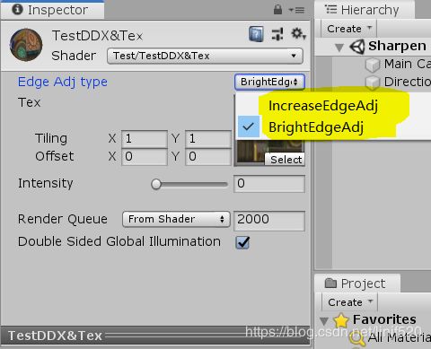
IncreaseEdgeAdj=边缘突出-锐化-增加差值;BrightEdgeAdj=边缘突出-增加亮度
边缘突出-锐化-增加差值
使用(ddx(c ) + ddy(c )),没有绝对值,会然边缘的像素亮度差异变大,即:加强边缘突出
边缘突出-增加亮度
fwidth(c ) ==> abs(ddx(c )) + abs(ddy(c ))
使用fwidth函数,可以看出,会是边缘变亮,突出边缘
高度贴应用
高度图,法线图,都是属于凹凸图的其一
在下面Project提供的源Unity工程的 HeightMap.unity 场景
准备一张高度图
高度图博文
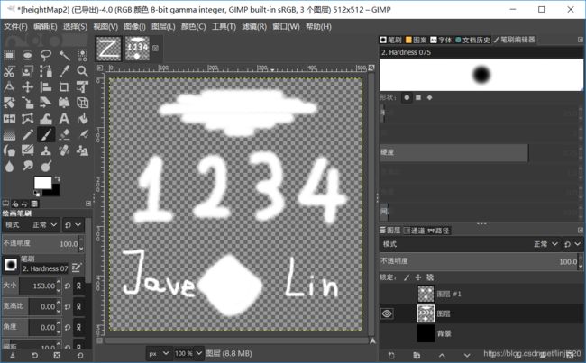
用PS或是GIMP随便画一个黑白的高度图就好了,注意我们的画笔需要设置成软笔刷,这样才会有渐变过渡,不然笔刷太硬,没啥过渡的灰度,那么shader渲染出来的法线角度太陡,就不太容易观察法线对光影的影响。
图片导出jpg就好了,不需要alpha,因为我们shader只要一个通道的值就好R通道。
如下图,我们用GIMP制图
导出到Unity中,再设置一下不需要alpha source,如下图
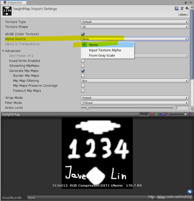
在导出来的jpg我们可以看到只有黑白
黑色表示没有越是接近黑色,说明高度越低,全黑,说明完全没有高度值影响
反之,白色说明就是有高度。
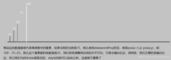
我们调整表面法线就就是用这些相邻像素的高度差异作为影响当前法线的水平、垂直(法线:xy)的因数,即可调整法线。
如果调整法线,如下图:
Shader
// jave.lin 2019.07.02
Shader "Test/TestDDX&HeightMap"
{
    Properties
    {
        [KeywordEnum(LMRTMB,CMRCML,NAVDDXPOSDDY)] _S ("Sample Type", Float) = 0
        _Color("Main Color", Color) = (1,1,1,1)
        _MainTex("Main Tex", 2D) = "white" {}
        _HightMap("Hight Map", 2D) = "white" {}
        _Intensity("Intensity", Range(0, 20)) = 5
        _SpecuarlIntensity("Specular Intensity", Range(0, 100)) = 80
        _SpecuarlStrengthen("Specular Strengthen", Range(0, 1)) = 0.5
    }
    SubShader
    {
        Tags { "Queue"="Transparent" }
        Pass
        {
            CGPROGRAM
            #pragma vertex vert
            #pragma fragment frag
            #pragma multi_compile _S_LMRTMB _S_CMRCML _S_NAVDDXPOSDDY

            #include "UnityCG.cginc"
			#include "Lighting.cginc"
            struct appdata
            {
                float4 vertex : POSITION;
                float2 uv : TEXCOORD0;
                float3 normal : NORMAL;
                float4 tangent : TANGENT;
            };
            struct v2f
            {
                float4 vertex : SV_POSITION;
                float2 uv : TEXCOORD0;
                float3 lightDir : TEXCOORD1;
                float3 viewDir : TEXCOORD2;
                float3 normal : TEXCOORD3;
            };
            fixed4 _Color;
            sampler2D _MainTex;
            float4 _MainTex_ST;
            sampler2D _HightMap;
            float4 _HightMap_TexelSize; // 1/w, 1/h, w, h
            float _Intensity;
            float _SpecuarlIntensity;
            float _SpecuarlStrengthen;
			inline float3x3 getTBN (inout float3 normal, float4 tangent) {
				float3 wNormal = UnityObjectToWorldNormal(normal);		    // 将法线从对象空间转换到世界空间
				float3 wTangent = UnityObjectToWorldDir(tangent.xyz);		// 将切线从对象空间转换到世界空间
				float3 wBitangent = normalize(cross(wNormal, wTangent));	// 根据世界空间下的法线,切线,叉乘算出世界空间下的副切线
                normal = wNormal;
				return float3x3(wTangent, wBitangent, wNormal);			    // 根据世界空间下的法线,切线,副切线,组合成TBN,可将切线空间下的法线转换到世界空间下
			}
            v2f vert (appdata v)
            {
                v2f o;
                o.vertex = UnityObjectToClipPos(v.vertex);
                o.uv = TRANSFORM_TEX(v.uv, _MainTex);
                float3x3 tbn = getTBN(v.normal, v.tangent);
                // w2t or t2w可以参考我之前写的:Unity Shader - 切线空间的法线贴图应用(T2W & W2T)
                // https://blog.csdn.net/linjf520/article/details/94165872
                o.lightDir = mul(tbn, normalize(_WorldSpaceLightPos0.xyz)); // w2t : world to tangent space
                o.viewDir = mul(tbn, normalize(_WorldSpaceCameraPos.xyz - mul(unity_ObjectToWorld, v.vertex))); // w2t : world to tangent space
                o.normal = mul(tbn, v.normal); // w2t : world to tangent space
                return o;
            }
            fixed4 frag (v2f i) : SV_Target
            {
                fixed4 c = tex2D(_MainTex, i.uv);
                // 三种采样方式:本质方法是一样的,类似两个3x3的卷积核处理
                #if _S_LMRTMB
                /*
                one:
                | 0| 0| 0|
                |-1| 0| 1|
                | 0| 0| 0|

                two:
                | 0|-1| 0|
                | 0| 0| 0|
                | 0| 1| 0|
                */
                // 这种方式是参考:Unity Shader-法线贴图(Normal)及其原理
                // https://blog.csdn.net/puppet_master/article/details/53591167
                float offsetU = tex2D(_HightMap, i.uv + _HightMap_TexelSize * float2(-1, 0)).r - tex2D(_HightMap, i.uv + _HightMap_TexelSize * float2(1, 0)).r;
                float offsetV = tex2D(_HightMap, i.uv + _HightMap_TexelSize * float2(0, 1)).r - tex2D(_HightMap, i.uv + _HightMap_TexelSize * float2(0, -1)).r;
                #elif _S_CMRCML
                /*
                one:
                | 0| 0| 0|
                | 0| 1|-1|
                | 0| 0| 0|

                two:
                | 0|-1| 0|
                | 0| 1| 0|
                | 0| 0| 0|
                */
                fixed cr = tex2D(_HightMap, i.uv).r;
                float offsetU = (cr - tex2D(_HightMap, i.uv + _HightMap_TexelSize * float2(1, 0)).r) * _Intensity;
                float offsetV = (cr - tex2D(_HightMap, i.uv + _HightMap_TexelSize * float2(0, -1)).r) * _Intensity;
                #else // _S_NAVDDXPOSDDY
                /*
                one:
                | 0| 0| 0|
                | 0|-1| 1|
                | 0| 0| 0|

                two:
                | 0| 0| 0|
                | 0|-1| 0|
                | 0| 1| 0|
                */
                fixed h = tex2D(_HightMap, i.uv).r;
                float offsetU = -ddx(h); // 右边像素采样 - 当前像素采样 = U的斜率,这里我们取反向,因为我们需要的是当前-右边的值,而ddx是固定的right-cur,所以我们只能取反
                float offsetV = ddy(h); // 下边像素采样 - 当前像素采样 = V的斜率,这里我们不用取反向,斜率方向刚刚好是我们需要的
                #endif // end _S_LMRTMB

                // 调整tangent space normal
                float3 n = normalize(i.normal.xyz + float3(offsetU, offsetV, 0) * _Intensity);
                // 为了测试法线,添加了diffuse与specular的光照因数
                // diffuse
                float ldn = dot(i.lightDir, n) * 0.5 + 0.5;
                fixed3 diffuse = _LightColor0.rgb * _Color * ldn * c.rgb * tex2D(_MainTex, i.uv);
                // specular
                float3 halfAngle = normalize(i.lightDir + i.viewDir);
                float3 hdn = max(0, dot(halfAngle, n));
                fixed3 specular = _LightColor0.rgb * _Color * pow(hdn, 100 - _SpecuarlIntensity) * _SpecuarlStrengthen;
                fixed3 combined = diffuse + specular;
                return fixed4(combined, 1);
            }
            ENDCG
        }
    }
}
其中有三种算法方式,前两种基本一样,支持采样坐标不太一样,最后一种就是使用偏导函数DDX,DDY来处理的
整体运行效果
还有三种不同算法的使用
采样质量从高到底(对应选项从上到下),最后一种就是DDX,DDY
无论用的是那种方式,我们都是采用高度图中相邻像素的灰度值(这里我们用R通道当灰度值,因为只有黑白,无所谓)相减,得到的差值我们当做是:当前像素就临近像素的高度斜率,然后用这个斜率调整对应水平、垂直的,法线:xy值。
Flat Shading 应用
在下面Project提供的源Unity工程的 ShowTBN.unity 场景
Shader
// jave.lin 2019.07.02
Shader "Test/TestDDX&TBN"
{
    Properties
    {
        _HightMap("Hight Map", 2D) = "white" {}
    }
    SubShader
    {
        Pass
        {
            CGPROGRAM
            #pragma vertex vert
            #pragma fragment frag
            #include "UnityCG.cginc"
            struct v2f
            {
                float4 vertex : SV_POSITION;
                float3 worldPos : TEXCOORD0;
            };
            sampler2D _HightMap;
            float4 _HightMap_TexelSize; // 1/w, 1/h, w, h
            v2f vert (float4 vertex : POSITION)
            {
                v2f o = (v2f)0;
                o.vertex = UnityObjectToClipPos(vertex);
                o.worldPos = mul(unity_ObjectToWorld, vertex);
                return o;
            }
            fixed4 frag (v2f i) : SV_Target
            {
                float3 wt = -ddx(i.worldPos); // world space tangent = worldPos(curx + 1, cury) - worldPos(cur, cury)
                float3 wb = ddy(i.worldPos); // world space bitangent = worldPos(curx, cury + 1) - worldPos(cur, cury)
                float3 wn = normalize(cross(wt, wb)) * 0.5 + 0.5; // world space normal
                //类似flat shader
                //平坦着色,没有插值,因为偏导函数只能在同一三角面内处理,没有插值的
                //return fixed4(n, 1);
                float3 wl = normalize(UnityWorldSpaceLightDir(_WorldSpaceLightPos0.xyz));
                float ldn = dot(wl, wn) * 0.5 + 0.5;
                float4 c = 0;
                c.rgb = ldn * wn;
                c.a = 1;
                return c;
            }
            ENDCG
        }
    }
}
主要看我们的法线如果求得
                float3 wt = -ddx(i.worldPos); // world space tangent = worldPos(curx + 1, cury) - worldPos(cur, cury)
                float3 wb = ddy(i.worldPos); // world space bitangent = worldPos(curx, cury + 1) - worldPos(cur, cury)
                float3 wn = normalize(cross(wt, wb)) * 0.5 + 0.5; // world space normal
就算在app to shader阶段没有normal传入,我们也可以通过偏导函数来求得wn世界空间的法线
然后添加了diffuse光照
但要注意,我们在像素阶段用ddx求出来的tbn是相对整个三角面的,所以没有插值,效果就如同Flat shader一样,没有对法线插值。
运行效果
Project
TestDerivativeFunc 提取码: 7jur
References
- An introduction to shader derivative functions
- 凹凸贴图(Bump Map)
- hlsl函数 ddx ddy