7 zedboard DMA and Animation
DMA and Animation
In this lab, we will see how to transfer mass amount of data into or out of memory without processor intervention. There are several Direct Memory Controllers available on the Zynq chip, the one we are interesting in is the DMAC. The DMAC is available in the PS-side of the chip. Steps needed to initiate a DMA transfer are covered. An application is developed that utilizes DMAC to transfer bitmaps of a certain character(Alex the alien) into the display controller memory region (The OLED screen displays Alex moving around ( In animation)). Another application to control Alex using the push buttons is developed as well.
Lab6 Design Flow
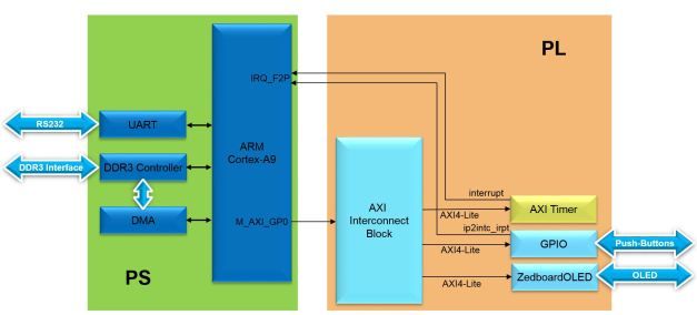
Lab6 Block Diagrm
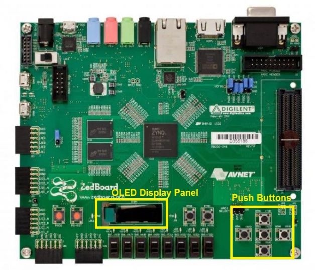
Lab6 Board Interface
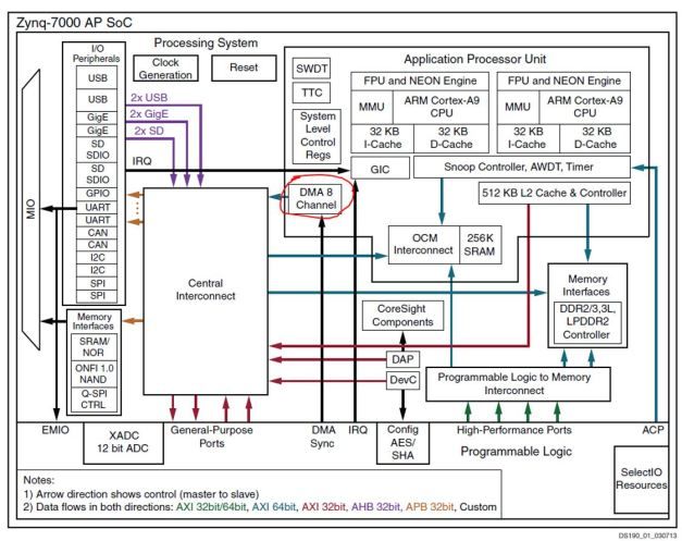
Direct Memory Access (DMA) controllers are widely used in both embedded systems and regular computing platforms primarily to reduce the workload on the processor and enhance the system’s overall response. In general, the task of a DMA controller is to transfer data into or out of memory without processor intervention once the processor has set up the transfer. DMA can significantly increase system performance if used properly. DMAs can be found in almost all devices that deal with mass amount of data such as: Video-, Ethernet-, USB-, Hard/Solid disk drive- controllers. There are several DMA controllers available on the Zynq chip, the one we will be interesting in ,is the DMAC. The DMAC is available in the PS-side of the chip. It is connected to the Zynq’s central interconnect and uses the AXI bus to perform transfers. The DMAC employs 64-bit AXI transfers between system memories and the Zynq’s Programmable Logic (PL). Eight channels are available which allow the DMAC to serve eight separate devices. It is circled in red in the below architecture diagram of the Zynq family.
Zynq Hardware Architecture – DMAC circled in red
The DMAC is able to move large amounts of data without processor intervention once the processor has set up the transfer. The source and destination memories can be anywhere in the system (PS or PL). The memory map for the DMAC includes DDR, OCM(On Chip Memory), linear addressed Quad-SPI read memory, SMC(Static Memory Controller) memories and PL peripherals or memory attached to an M_GP_AXI interface. The DMAC internally has a specialized processor (DMA Instruction Execution Engine) with flexible instruction set for DMA transfers. A block diagram of the DMAC is shown below:
DMAC Block Diagram
The driver of the DMAC (xdmaps) allows us to communicate with the DMA instruction execution engine in a user friendly fashion.
In order to set-up a DMA transfer, the following procedures should be conducted:
1.Specify starting address of source data in memory.
2.Set length of data to be transferred.
3.Specify address of destination region (where you want to transfer the data to).
4.Write a done handler to specify what need to be done once the transfer is complete.
5.Write a fault handler in case the transfer fails to complete (a default handler is available by the driver).
6.Send these data to the DMA instruction execution engine and start the transfer.
In this lab, we will animate an alien character named Alex on the OLED using DMA transfers. The animation of Alex is achieved by displaying bitmaps of Alex that minimally differ from each other(the legs part) as illustrated in the figures below:
Alex’s Bitmaps
when Bitmap1 and Bitmap2 are sequentially displayed on the same position on the OLED with some time delay, it would give the impression as if Alex’s legs are moving. By keep playing these two bitmaps and moving the bitmaps into different positions, it would make Alex looks as if he is walking. These two bitmaps will be stored in the ZedboardOLED controller, specifically in its characters library which contains 32 free spaces to accommodate new characters. Bitmap1 is going to be saved in ASCII code (24)10 0x18, while Bitmap2 in (25)10 0x19. Every time we wish to make Alex appear on a specific location on the OLED we need to send 0x18 or 0x19(We will use the Zedboard OLED driver for this) to the exact byte of the register associated with that position, as we remember from lab3 that there are 4 pages, and each page has 16 positions, so in total there are 64 (16×4) possible positions Alex can fit in.
Data Registers
For instance, sending 0x18 to the first byte of slv_reg4 will make Alex appear on the first position of the second page(Page1). With the help of Zedboard OLED driver this is done by calling function print_char(ASCII code,page,position). “print_char(0x18,1,0)”.
Alex at second page(Page1)
Different frames representing Alex in different positions(On the OLED screen) and postures( legs open , legs closed) are created and stored in a file named all_frames. This file will be loaded in region (A) on the DDR3 memory using SDK.
all_frames file ( Opened using HxD Editor)- Click to enlarge
To display the binary content of a file you need to use a HEX editor. The HxD Editor program is a recommended one.
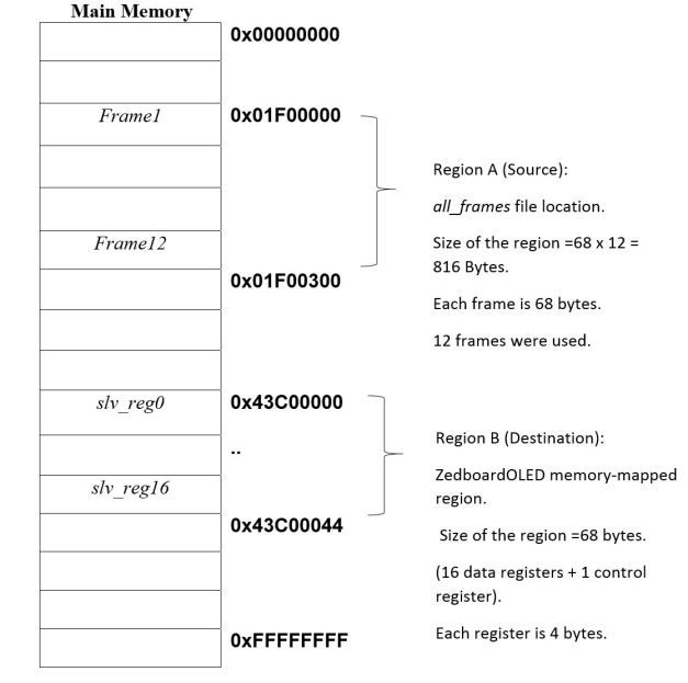
A frame is a complete image of the ZedboardOLED controller’s memory region (68 bytes). Why 68 ? (4 pages x 16 positions = 64 bytes for data) +(4 bytes of the control register). There are 12 frames stored in file all_frames. The task of the DMA controller is to swap in these frames(will be stored in Region A in the DDR memory) periodically into the actual ZedboardOLED controller’s memory-mapped region(Region B) making Alex move around the screen.
DMA-involved memory regions
The way the processor interacts with the DMA is by passing a command structure to the DMA (XDmaPs_Cmd), which will be filled with the source (Region A) and destination (Region B) addresses along with other information. This command will be actually passed to the DMA instruction execution engine through the XDmaPs_Start (XDmaPs * InstPtr,unsigned int Channel,XDmaPs_Cmd * Cmd,int HoldDmaProg)function.
The hardware setup for this experiment is exactly the same as of the previous lab(Lab5 Hardware Timers). The Timer is used to time the period of transferring a new frame, The GPIO is used for the second application(Alex control). The UART is there for enabling a debugging interface if needed. The DMAC is in the PS and its enabled by default so there is nothing we need to do on the hardware side other than using the previous lab files (If you didn’t do the precious,you can download the complete source code from My GitHub page).
Objectives
1.Introduce the DMA controller of the Zynq family available within the PS.
2.Use a DMA controller to transfer data between two regions of memory.
3.Examine different functions of the xdmaps driver.
4.Download data files onto the Zedboard DDR main memory using SDK.
5.Introduce the concept of animation.
6.Learn how to create multiple application in SDK.
7.Practice how to build up on an existing code and add desired functionalities as needed.
Procedures
A-Copy lab5 content into a new directory
1.Create a new folder in your “C:\embeddedcentric” directory, name this folder “lab6″.
2.Open the previous lab directory “C:\embeddedcentric\lab5“. Copy all content of that directory EXCEPT “lab4.sdk”. (Use the Ctrl+A to select all files, then hold the Ctrl Key to de-select “lab4.sdk” ). Note: ( If you don’t have lab5 files, you can download it from my GitHub page).
Copy Lab5 content
3.Paste the content in the newly created folder “C:\embeddedcentric\lab6“.
Paste content in lab6 folder
4.Open Vivado by double clicking on “lab4.xpr”.IMPORTANT NOTE: Do not rename the Vivado project file. Keep it as is “lab4.xpr” even though its the sixth lab. Trying to rename this file would result in a mess later on.
B-Update characters library of ZedboardOLED to include the bitmaps of Alex
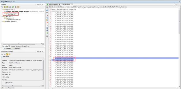
1.In the Source pane, expand the Coefficient Files group and double click on charLib.coe to open it. This file represents the static data that will be stored in the ZedboardOLED controller’s characters library.
charLib.coe Characters Library
2.Replace lines (27) and (28) with the lines below. These lines represents the two 32bits(8×8) bitmaps of Alex. Click Save ![]() .
.
98,5C,B6,5F,5F,B6,5C,98,
18,DC,36,5F,5F,36,DC,18,
We choose 27 and 28 because as stated earlier we want to associate ASCII code 24 and 25 with Alex’s bitmaps, and since there is an offset of 3 between the ASCII code and the address in charLib.coe the bitmaps were stored at (24+3) and (25+3 ) respectively.
Note: If you downloaded the source code from my GitHub page, this step had already been done.
C-Regenerate Bitstream to reflect the new modification
1.In the Design Runs pane in the lower section of Vivado, select synth_1, right click, and select Reset Runs.
Reset Runs- synth_1
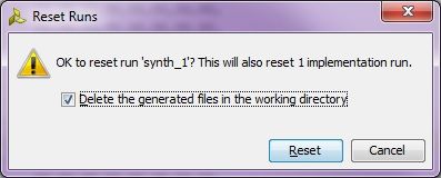
2.A confirmation message pops up. Make sure that Delete the generated files in the working directory is checked, then click Reset.
Reset Runs Confirmation
3.Select synth_1 again, right click then select Generate Bitstream.
Generate Bitstream from Design Runs
Synthesis and implementation will take a while to complete (around 10 mins).
D-Export hardware design to SDK
1.Click File > Export > Export Hardware, make sure you select Include bitstream.
Export Hardware to SDK
2.Select File>Launch SDK. This will open up Launch SDK dialog, leave default options as as, and click OK. All the hardware files related to the design have now been exported to SDK and we can work on the software.
We are now done with the hardware configuration of the system. You may close Vivado.
E-Working with SDK, (Including download Bitstream and run the two applications)
1.In SDK, select File > New > Application Project.
2.In the Application Project window, enter the parameters as provided in the snapshot below and click Next
New Standalone C Project- animation_test
In the next window, select Empty Application from the available templates and click Finish. This will compile the BSP and the related drivers.
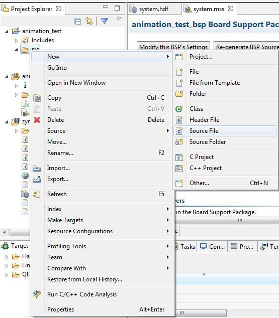
3.Expand animation_test directory, right click on src directory, New->Source File.
New C Source File -lab6.c
4.In the next window that shows up type “lab6.c” in the Source file field, and click Finish. This will create an empty C file in the src directory.
lab5.c empty source file created in SDK
5.Paste the content of lab6.c (Available on my Github page) in the editor view of lab6.c in SDK , and click on Save ![]() or hit (Ctrl+S). By doing so both lab6 application, and its BSP are compiled automatically and the executable .elf file is generated(the default settings of SDK triggers compilation with save). This is the executable file that the ARM processor on the PS side of the Zynq will execute. lab6.c is an extended version of lab5.c. The additions on top of lab5.c are enclosed by comments. The additions include function XDma_Config() , DmaISR() , a modified IntcInitFunction() and a modified TMR_Intr_Handler().
or hit (Ctrl+S). By doing so both lab6 application, and its BSP are compiled automatically and the executable .elf file is generated(the default settings of SDK triggers compilation with save). This is the executable file that the ARM processor on the PS side of the Zynq will execute. lab6.c is an extended version of lab5.c. The additions on top of lab5.c are enclosed by comments. The additions include function XDma_Config() , DmaISR() , a modified IntcInitFunction() and a modified TMR_Intr_Handler().
XDma_Config() creates a DMA command. The command has 9 fields, two fields of our concern are the Channel Control(ChanCtrl) field, and the DMA block descriptor(BD) field. In the DMA block descriptor field three parameters are specified:
(1)Source starting address (SrcAddr).
(2)Destination starting address(DstAddr).
(3)Number of bytes in the block(Length).
DMA block descriptor(BD) field
On the other hand, the channel control field(ChanCtrl) specifies parameters related to the AXI bus transaction.
DMA Channel Control (ChanCtrl) field
XDma_Config() also, sets the done handler ( function to be called when a DMA transaction is completed) and then it starts the DMA.
DmaISR() is called upon every successful DMA transaction. Inside our simple DMA ISR we are simply sending a message saying (DMA stage # passed) to the UART. “#” represent the frame number.
The modified IntcInitFunction() includes code for enabling interrupts on the DMA controller and its corresponding ports on the GIC. It also sets the fault handler for the DMA (function to be called when a DMA transaction has failed).
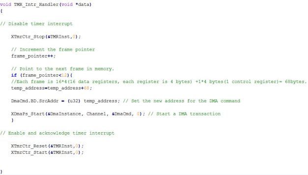
TMR_Intr_Handler() do something completely different than what it used to do in the previous lab. It is responsible for managing the address of the next frame to be copied from Region A to Region B (frame_pointer), and initiating another DMA transaction until the 12 frames have been copied.
TMR_Intr_Handler() in Lab6
6.Select Xilinx Tools-> Program FPGA to download the Bitstream (this will take few seconds).
![]()
Download Bitstream to the PL
7.Download file all_frames from my GitHub page.
IMPORTANT NOTE: Make sure you save file all_frames in a directory that does NOT include spaces. For example, don’t save it in “My Document”. Vivado doesn’t work well with source files saved in directories with spaces in their name. Otherwise , you will get a series of annoying Java Run-time errors. I recommend saving the file in a folder names “data” on your “C:\” drive.
Save file all_frames in a folder with NO spaces
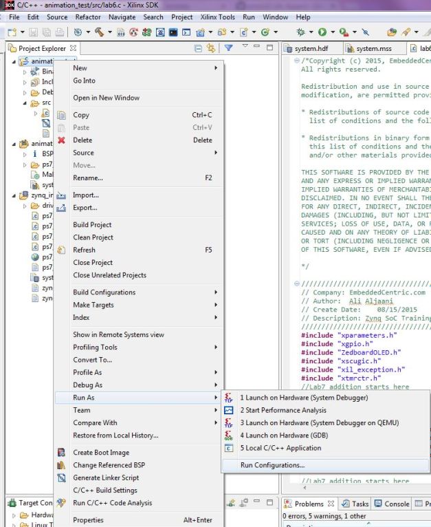
8.Right click on animation_test project directory, click on Run As > Run configurations
Run Configurations
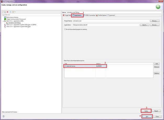
In the Run Configurations window, double click on Xilinx C/C++ application (GDB)to create the animation_test Debug configuration profile.
Run Configurations Window
In the window on the right, select Application and click Add. Browse to the location where the file all_frames is stored, select it and click Open. This will download all_frames file to memory before launching the application. Enter 0x01f00000 (Region A starting address) to tell SDK where to store that file. Click Apply then Run.
Download a data file (all_frames) to memory before running application lab6.c
You should see Alex walking around on the OLED screen by now! See the demo Video
F-Running the second application ( Alex Control)
In this step, we will see how we can easily build up on an existing code and add desired functionality as needed. Its desired to make Alex move! We want to make Alex controllable by the push buttons in such a way when we press BTNU(Upper push button) Alex goes up, BTND Alex goes down , BTNR Alex goes right, BTNL Alex goes left. Keeping in mind not to to cross the bounideris of the screen .
Let’s address this new requirement by thinking of the OLED as a two-dimensional grid. The pages represents the y-axis and the characters positions represent the x-axis.
Alex Control Grid
We will use function print_char(char,page,position) of the Zedboard OLED driver. It prints a character(char) on the OLED at the page and the position specified by the second and third arguments respectively. But now ( page=y-axis, position=x-axis).
Remember that we saved Alex’s bitmaps at charLib.coe addresses 27 and 28 respectively so their ASCII = address-3(offset). therefore its 24 and 25 respectively.
With that in mind, calling function print_char(24,0,0) would display Alex on the first position of the first page in other words at (0,0) in x-y coordinates.
Now let’s see how we can use that to make Alex controllable.
1.Select File > New > Application Project, to create a new software application for Alex control.
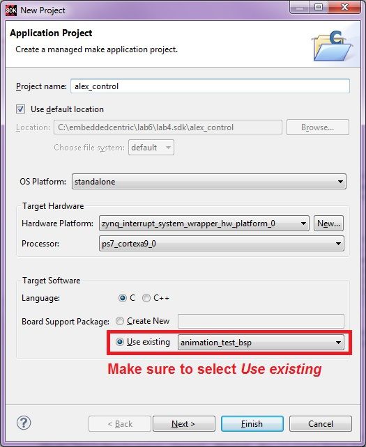
2.In the Application Project window, enter the parameters as provided in the snapshot below. There is no need to create a new BSP, therefore use the one for animation_test. click Next.
New Standalone C Project- alex_control
In the next window, select Empty Application from the available templates and click Finish.
3.Select animation_test-> src, right click on lab6.c and select copy.
copy lab6. c file from animation_test
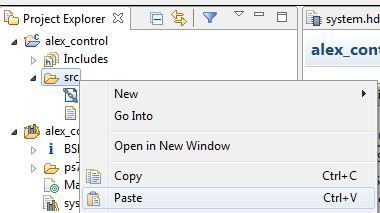
4.Select alex_control-> src right click and select paste.
copying lab6.c to alex_control application project
5.Select the newly copied file, right click, and select Rename.Enter lab6_app2 ,then click OK.
Rename to lab6_app2.c
Now we have a fresh copy of the code that we can modify as we wish to satisfy the new requirements.
6.The first thing to do is to comment out the part where the DMA is enabled. DMA is not needed in here any more, we are not doing anything related to DMA or animation, we just want to make Alex controllable through the push buttons. To stop using the DMA, comment out function XDma_Config(DMA_DEVICE_ID); line 230 by adding “//” in front of it.
Comment out line 230 ( Function DMA_Config)
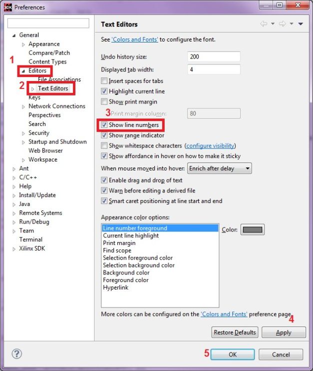
Note: you can always view the lines number by going to Window->Preference->Editors->Text Editors and checking the Show line numbers.
Show line numbers
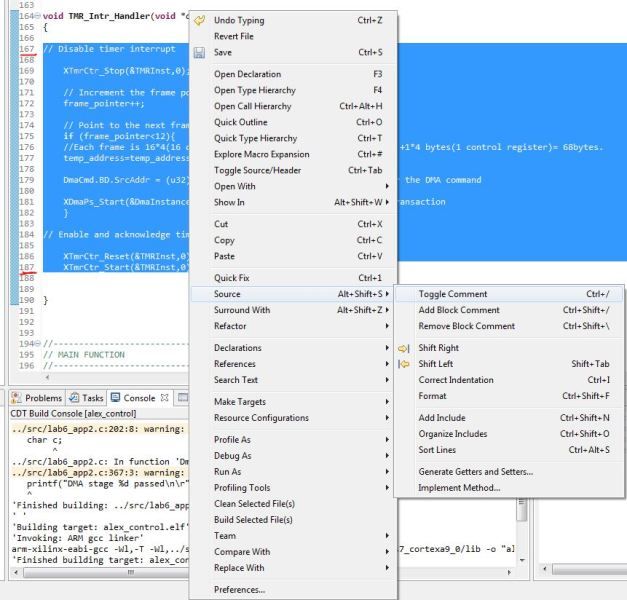
7.Comment out the body of the timer ISR (TMR_Intr_Handler). It is responsible on managing the address of the next frame for DMA transactions. That is no longer needed as we are not using the DMA anymore. Select lines 167-187 , right click Source-> Toggle Comment.
Comment out line lines167-187
8.Declare two static global variables to hold the coordinates of Alex across different functions calls.
Add the following two statements in lines 87-88:
static unsigned int x;
static unsigned int y;
The code should look like this:
Add two static global variables for Alex’s location
9.Add the definition of function show_alex() at the very end of the code. show_alex() displays Alex at the specified x and y coordinates. It uses function print_char() of the Zedboard OLED driver(developed in Lab3).
void show_alex(int x, int y)
{
print_char(24,y,x);
}
The code should look like this :
Add function show_alex at the end of the code
10.Modify the switch case statements inside the push buttons ISR “BTN_Intr_Handler()”. The code below takes care of making Alex controllable by the push buttons.
switch (btn_value)
{
//Checking if BTNC was pressed. Action: Show Alex in the middle
case 1:
x=8;
y=2;
clear_OLED();
show_alex(x,y);
break;//Checking if BTND was pressed. Action: Check for boundary and move Alex down.
case 2:
if (y<3)
{
y=y+1;
clear_OLED();
show_alex(x,y);
}
break;//Checking if BTNL was pressed. Action: Check for boundary and move Alex left.
case 4:
if (x>0)
{
x=x-1;
clear_OLED();
show_alex(x,y);
}
break;//Checking if BTNR was pressed. Action: Check for boundary and move Alex right.
case 8:
if (x<15)
{
x=x+1;
clear_OLED();
show_alex(x,y);
}
break;//Checking if BTNU was pressed. Action: Check for boundary and move Alex up.
case 16:
if (y>0)
{
y=y-1;
clear_OLED();
show_alex(x,y);
}
break;default:
break;}
Your code should look like this :
Modified switch case in BTN_Intr_Handler()
Click on Save ![]() to save and compile the application.
to save and compile the application.
11.Select alex_control project directory-> Run As-> Launch on Hardware (GDB) to run alex_control application on the ARM processor. After the download is complete, you can control Alex using the push buttons. See demo video
By this you have completed Lab6-DMA and Animation. You can find the complete solution of this lab in here.

