鱼眼相机外参的计算和图像的透视变换
0.前言
之前的学习中已经完成了基于鱼眼相机内参进行图像畸变校正,和相机坐标系与像素坐标系之间的转换。这一次将引入相机外参,进行外参的标定计算和基于外参+内参的鱼眼相机透视变换。
1.相机外参的定义
世界坐标系映射至相机坐标系时,需要知道世界坐标系相对于相机坐标系的变换矩阵(平移矩阵R +旋转向量T ),对于世界坐标系中的点Pw(Xw,Yw,Zw),其在相机坐标系中的坐标Pc(Xc,Yc,Zc)通过下式求得
Pc=R*Pw+T
我们把[R,T]称为相机外参,为了求解外参,1)需要先确定世界坐标系的分布,2)需要建立有关外参的方程组。一种常见的方法是在确定了的世界坐标系中铺设带有某种指定特征(譬如棋盘格)的标定布,标定布中特征点的世界坐标已知,然后在相机成像图片中计算得到特征点的像素坐标。问题转换为已知特征点的世界坐标,像素坐标,相机的内参和畸变参数,计算世界坐标系变换至相机坐标系的欧式变换矩阵(即外参)的问题。
2.相机外参的求解
具体数学计算流程尚未仔细阅读,这里直接调用了cv::SolvePnP函数求解R和T,函数具体说明见https://docs.opencv.org/3.4.6/d9/d0c/group__calib3d.html#ga549c2075fac14829ff4a58bc931c033d,这里对其调用形式做如下简要说明。
@函数说明:根据对应的3D-2D坐标计算相机位姿

@objectPoints,点集在世界坐标系中的坐标,Nx3的1通道或者1xN/Nx1的三通道数据,其中N为点数,vector可以作为输入。

@imagePoints,点集在像素坐标系中的坐标,Nx2的1通道或者1xN/Nx1的两通道数据,其中N为点数,vector可以作为输入。

@cameraMatrix,3X3的相机内参

@distCoeffs,相机内参,形式为 (k1,k2,p1,p2[,k3[,k4,k5,k6[,s1,s2,s3,s4[,τx,τy]]]])

@useExtrinsicGuess,flags是SOLVEPNP_ITERATIVE时生效。如果为1,方程使用输入的rvec和tvec作为初始值之后进行优化

@rvec tvec,输出的旋转向量和平移向量,使用cv::Rodrigues可以将旋转向量变换为旋转矩阵

@flags,选项较多,如果输入点数超过4建议选择SOLVEPNP_ITERATIVE

CV_EXPORTS_W bool solvePnP( InputArray objectPoints, InputArray imagePoints,
                            InputArray cameraMatrix, InputArray distCoeffs,
                            OutputArray rvec, OutputArray tvec,
                            bool useExtrinsicGuess = false, int flags = SOLVEPNP_ITERATIVE );
3.实验
测试流程如下,首先标定得到鱼眼相机的内参和畸变参数;之后将其固定在汽车尾部,并尝试标定得到相机外参;利用外参,内参,畸变参数将相机原始图像投影至地面,即得到鸟瞰图。
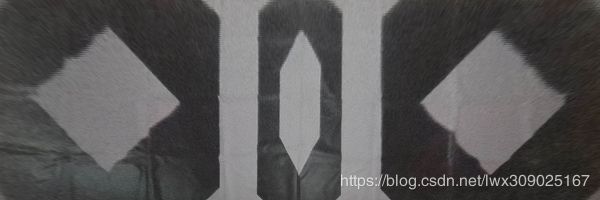
在地面铺设标定布如下所示,手动定义左方、右方两个白色四边形角点的世界坐标;另外因为计算特征点的像素坐标不是本文的重点,角点的像素坐标也手动给出。
之后计算得到相机外参,然后将原始图像投影至地面指定区域,结果如下图所示,达到了预期效果。
主要代码如下。
void ProjectPointFromOriginToUndistorted(cv::Matx33d K, cv::Vec4d D, cv::Point2f input, cv::Point2f& output)
{
	float x, y, theta, theta_d, r, x_origin, y_origin;
	float theta_cal[2], d_theta;

	x_origin = input.x - K(0, 2);
	y_origin = input.y - K(1, 2);
	theta_d = sqrt(x_origin*x_origin + y_origin*y_origin)
		/ K(0, 0);
	theta_cal[0] = 0;
	theta_cal[1] = CV_PI / 2;
	d_theta = fabs(theta_cal[1] - theta_cal[0]);
	while (d_theta > 0.01)
	{
		float val[3];
		float middle_theta_cal = 0.5 * (theta_cal[1] + theta_cal[0]);

		val[0] = theta_cal[0] + D(0)*pow(theta_cal[0], 3)
			+ D(1)*pow(theta_cal[0], 5) + D(2)*pow(theta_cal[0], 7)
			+ D(3)*pow(theta_cal[0], 9) - theta_d;

		val[1] = theta_cal[1] + D(0)*pow(theta_cal[1], 3)
			+ D(1)*pow(theta_cal[1], 5) + D(2)*pow(theta_cal[1], 7)
			+ D(3)*pow(theta_cal[1], 9) - theta_d;

		val[2] = middle_theta_cal + D(0)*pow(middle_theta_cal, 3)
			+ D(1)*pow(middle_theta_cal, 5) + D(2)*pow(middle_theta_cal, 7)
			+ D(3)*pow(middle_theta_cal, 9) - theta_d;

		if (fabs(val[2]) < 1e-6)
		{
			break;
		}
		if (val[0] * val[2] > 0)
		{
			theta_cal[0] = middle_theta_cal;
		}
		else
		{
			theta_cal[1] = middle_theta_cal;
		}
		d_theta = theta_cal[1] - theta_cal[0];
	}

	theta = 0.5 * (theta_cal[1] + theta_cal[0]);
	x = tan(theta) / sqrt(x_origin*x_origin + y_origin*y_origin) * x_origin;
	y = tan(theta) / sqrt(x_origin*x_origin + y_origin*y_origin) * y_origin;
	output.x = x*K(0, 0) + K(0, 2);
	output.y = y*K(1, 1) + K(1, 2);
}

void CalcCameraExtrinsics()
{
	std::vector pixel_uv_vec;
	std::vector point_world_vec;
	cv::Mat rvec, tvec, R, T;

	cv::Mat K(3, 3, CV_64FC1);
	K.at(0, 0) = 290.62; K.at(0, 1) = 0; K.at(0, 2) = 643.44;
	K.at(1, 0) = 0; K.at(1, 1) = 290.62; K.at(1, 2) = 365.61;
	K.at(2, 0) = 0; K.at(2, 1) = 0; K.at(2, 2) = 1;

	cv::Mat D(4, 1, CV_64FC1);
	D.at(0, 0) = 0.165618;
	D.at(1, 0) = 0.020838;
	D.at(2, 0) = -0.023782;
	D.at(3, 0) = 0.002512;

	point_world_vec.push_back(cv::Point3f(-3100, 0, 0));
	point_world_vec.push_back(cv::Point3f(-2250, 850, 0));
	point_world_vec.push_back(cv::Point3f(-1400, 0, 0));
	point_world_vec.push_back(cv::Point3f(-2250, -850, 0));
	point_world_vec.push_back(cv::Point3f(1400, 0, 0));
	point_world_vec.push_back(cv::Point3f(2250, 850, 0));
	point_world_vec.push_back(cv::Point3f(3100, 0, 0));
	point_world_vec.push_back(cv::Point3f(2250, -850, 0));

	pixel_uv_vec.push_back(cv::Point2f(298, 373));
	pixel_uv_vec.push_back(cv::Point2f(419, 338));
	pixel_uv_vec.push_back(cv::Point2f(441, 380));
	pixel_uv_vec.push_back(cv::Point2f(266, 444));
	pixel_uv_vec.push_back(cv::Point2f(835, 383));
	pixel_uv_vec.push_back(cv::Point2f(862, 341));
	pixel_uv_vec.push_back(cv::Point2f(987, 380));
	pixel_uv_vec.push_back(cv::Point2f(1013, 453));

	// 计算得到原始图像中像素点坐标在畸变校正后的图像中的坐标
	for (int i = 0; i < pixel_uv_vec.size(); i++)
	{
		cv::Matx33d K;
		cv::Vec4d D;
		K(0, 0) = 290.62; K(0, 1) = 0; K(0, 2) = 643.44;
		K(1, 0) = 0; K(1, 1) = 290.62; K(1, 2) = 365.61;
		K(2, 0) = 0; K(2, 1) = 0; K(2, 2) = 1;
		D(0) = 0.165618;
		D(1) = 0.020838;
		D(2) = -0.023782;
		D(3) = 0.002512;
		ProjectPointFromOriginToUndistorted(K, D, pixel_uv_vec[i], pixel_uv_vec[i]);
	}

	// 计算得到旋转向量和平移向量,将旋转向量转换为旋转矩阵
	cv::solvePnP(point_world_vec, pixel_uv_vec, K, cv::Mat(), rvec, tvec);
	cv::Rodrigues(rvec, R);

	T.create(4, 4, CV_64FC1);
	R.copyTo(T(cv::Rect(0, 0, 3, 3)));
	T.at(0, 3) = tvec.at(0, 0);
	T.at(1, 3) = tvec.at(1, 0);
	T.at(2, 3) = tvec.at(2, 0);
	T.at(3, 0) = T.at(3, 1) = T.at(3, 2) = 0;
	T.at(3, 3) = 1;

	// 验证计算得到的外参的准确性,通过利用计算得到的外参将世界坐标投影至像素坐标系
	// 并将结果与输入的像素坐标对比来验证
	for (int i = 0; i < point_world_vec.size(); i++)
	{
		// 世界坐标系变换至相机坐标系
		float ux, uy;
		cv::Mat pt_cam, pt_world;
		pt_world.create(4, 1, CV_64FC1);
		pt_world.at(0, 0) = point_world_vec[i].x;
		pt_world.at(1, 0) = point_world_vec[i].y;
		pt_world.at(2, 0) = point_world_vec[i].z;
		pt_world.at(3, 0) = 1;

		pt_cam = T*pt_world;

		// 相机坐标系变换至像素坐标系
		float x = pt_cam.at(0, 0);
		float y = pt_cam.at(1, 0);
		float z = pt_cam.at(2, 0);

		if (z < 1e-6)
			z = 1.f;

		float r = sqrtf(x * x + y * y);

		if (r < 1e-6)
		{
			// 位于光心
			ux = K.at(0, 2);
			uy = K.at(1, 2);
		}
		else
		{
			float theta = atan2f(r, z);

			float theta_d = 1.f;
			float res = 1.f;
			for (int i = 0; i < 4; ++i)
			{
				theta_d *= theta * theta;
				res += D.at(i, 0) * theta_d;
			}

			res *= theta;

			ux = x * K.at(0, 0) * res / r + K.at(0, 2);
			uy = y * K.at(1, 1) * res / r + K.at(1, 2);
		}
		printf("ux, uy: %f %f\n", ux, uy);
	}

	// 将图像透视变换至地面
	int img_w = 3000;
	int img_h = 1000;
	float world_w = 7000;// 单位为mm
	float scale = img_w / world_w;
	cv::Mat dst_img(img_h, img_w, CV_8UC3);
	cv::Mat src_img = cv::imread("back.bmp");
	for (int v = 0; v < img_h; v++)
	{
		for (int u = 0; u < img_w; u++)
		{
			// 目标图像到世界坐标系的映射
			float world_x, world_y, world_z;
			float ux, uy;
			world_x = (u - 0.5 * img_w) / scale;
			world_y = -(v - 0.5 * img_h) / scale;
			world_z = 0;

			cv::Mat pt_cam, pt_world;
			pt_world.create(4, 1, CV_64FC1);
			pt_world.at(0, 0) = world_x;
			pt_world.at(1, 0) = world_y;
			pt_world.at(2, 0) = world_z;
			pt_world.at(3, 0) = 1;

			pt_cam = T*pt_world;

			float x = pt_cam.at(0, 0);
			float y = pt_cam.at(1, 0);
			float z = pt_cam.at(2, 0);

			if (z < 1e-6)
				z = 1.f;

			float r = sqrtf(x * x + y * y);

			if (r < 1e-6)
			{
				ux = K.at(0, 2);
				uy = K.at(1, 2);
			}
			else
			{
				float theta = atan2f(r, z);

				float theta_d = 1.f;
				float res = 1.f;
				for (int i = 0; i < 4; ++i)
				{
					theta_d *= theta * theta;
					res += D.at(i, 0) * theta_d;
				}

				res *= theta;

				ux = x * K.at(0, 0) * res / r + K.at(0, 2);
				uy = y * K.at(1, 1) * res / r + K.at(1, 2);
			}
			if (ux < 0 || ux > src_img.cols - 1
				|| uy < 0 || uy > src_img.rows - 1)
			{
				dst_img.at(v, u) = cv::Vec3b(0, 0, 0);
			}
			else// 只是为了验证畸变校正流程,为方便这里用了最近邻差值
			{
				dst_img.at(v, u) = src_img.at((int)uy, (int)ux);
			}
		}
	}
	cv::imwrite("dst.bmp", dst_img);

}
测试中发现SolvePnP函数无法直接作用于鱼眼相机原始图像,具体地说,我把鱼眼相机中特征点的像素坐标、世界坐标、相机内参和畸变参数传入该函数之后,求得的R和T并不准确;查看函数说明时看到distCoeffs的形式为(k1,k2,p1,p2[,k3[,k4,k5,k6[,s1,s2,s3,s4[,τx,τy]]]]),但是鱼眼相机的畸变参数形式为(D1,D2,D3,D4),由此我判断该函数无法直接作用于鱼眼相机原始图像求解相机外参。既然函数不能接收鱼眼相机畸变参数,那就传入畸变校正后的像素坐标,并把畸变参数置为NULL;有关原始图像坐标到畸变校正后图像坐标的映射计算参考上一篇博客,测试发现这样处理之后可以得到正确的R和T。