USART配置 STM32cubemx配置USART
目录:
1.软件
2.程序
3.使用STM32CubxMX配置USART
4,.介绍程序的实现
一、软件:
(1)STM32CubeMX(2)KEIL5
硬件平台主IC:STM32F412RET6
二,见程序:main.c部分程序
#include "main.h"
#include "stm32f4xx_hal.h"
#include "usart.h"
#include "gpio.h"

#define led0_1  HAL_GPIO_WritePin(GPIOC, GPIO_PIN_0, GPIO_PIN_SET)
#define led1_1  HAL_GPIO_WritePin(GPIOC, GPIO_PIN_1, GPIO_PIN_SET)//IO口高电平输出
#define led2_1  HAL_GPIO_WritePin(GPIOC, GPIO_PIN_2, GPIO_PIN_SET)//IO口高电平输出

#define led0_0  HAL_GPIO_WritePin(GPIOC, GPIO_PIN_0, GPIO_PIN_RESET)
#define led1_0  HAL_GPIO_WritePin(GPIOC, GPIO_PIN_1, GPIO_PIN_RESET)//IO口低电平输出
#define led2_0  HAL_GPIO_WritePin(GPIOC, GPIO_PIN_2, GPIO_PIN_RESET)//IO口高电平输出

void Delay_Nus(uint32_t	t)//us延时
{
	uint8_t	i;
	while(t--)
	{
		i=25;
		while(i--);
	}
}

void Delay_Nms(uint32_t t)//ms延时
{
  while(t--)
  {
    Delay_Nus(1000);
  }
}

void SystemClock_Config(void);

uint8_t aRxBuffer[20];
int main(void)
{
  uint8_t aTxStartMessages[] = "\r\nPlease enter 10 characters:\r\n";
  HAL_Init();
  SystemClock_Config();//时钟
  MX_GPIO_Init();
  MX_USART1_UART_Init();
  while (1)
  {
    HAL_UART_Transmit_IT(&huart1 ,(uint8_t*)aTxStartMessages,sizeof(aTxStartMessages)); //发送函数
    HAL_UART_Receive_IT(&huart1,(uint8_t*)aRxBuffer,10); //接收函数
      led1_0;
      Delay_Nms(40);
      led1_1;
      Delay_Nms(40);
  }
}

void HAL_UART_RxCpltCallback(UART_HandleTypeDef *huart)
{
    UNUSED(huart);
    HAL_UART_Transmit(&huart1,(uint8_t*)aRxBuffer,10,0xFFFF);//(uint8_t*)aRxBuffer为字符串地址,10为字符串长度,0xFFFF为超时时间
}

void SystemClock_Config(void)//系统时钟
{
  RCC_OscInitTypeDef RCC_OscInitStruct;
  RCC_ClkInitTypeDef RCC_ClkInitStruct;
    /**Configure the main internal regulator output voltage
    */
  __HAL_RCC_PWR_CLK_ENABLE();

  __HAL_PWR_VOLTAGESCALING_CONFIG(PWR_REGULATOR_VOLTAGE_SCALE1);

    /**Initializes the CPU, AHB and APB busses clocks
    */
  RCC_OscInitStruct.OscillatorType = RCC_OSCILLATORTYPE_HSI;
  RCC_OscInitStruct.HSIState = RCC_HSI_ON;
  RCC_OscInitStruct.HSICalibrationValue = 16;
  RCC_OscInitStruct.PLL.PLLState = RCC_PLL_NONE;
  if (HAL_RCC_OscConfig(&RCC_OscInitStruct) != HAL_OK)
  {
    _Error_Handler(__FILE__, __LINE__);
  }
    /**Initializes the CPU, AHB and APB busses clocks
    */
  RCC_ClkInitStruct.ClockType = RCC_CLOCKTYPE_HCLK|RCC_CLOCKTYPE_SYSCLK
                              |RCC_CLOCKTYPE_PCLK1|RCC_CLOCKTYPE_PCLK2;
  RCC_ClkInitStruct.SYSCLKSource = RCC_SYSCLKSOURCE_HSI;
  RCC_ClkInitStruct.AHBCLKDivider = RCC_SYSCLK_DIV1;
  RCC_ClkInitStruct.APB1CLKDivider = RCC_HCLK_DIV1;
  RCC_ClkInitStruct.APB2CLKDivider = RCC_HCLK_DIV1;

  if (HAL_RCC_ClockConfig(&RCC_ClkInitStruct, FLASH_LATENCY_0) != HAL_OK)
  {
    _Error_Handler(__FILE__, __LINE__);
  }

    /**Configure the Systick interrupt time
    */
  HAL_SYSTICK_Config(HAL_RCC_GetHCLKFreq()/1000);

    /**Configure the Systick
    */
  HAL_SYSTICK_CLKSourceConfig(SYSTICK_CLKSOURCE_HCLK);

  /* SysTick_IRQn interrupt configuration */
  HAL_NVIC_SetPriority(SysTick_IRQn, 0, 0);
}
/**
  * @brief  This function is executed in case of error occurrence.
  * @param  None
  * @retval None
  */
void _Error_Handler(char * file, int line)
{
  /* USER CODE BEGIN Error_Handler_Debug */
  /* User can add his own implementation to report the HAL error return state */
  while(1)
  {
  }
  /* USER CODE END Error_Handler_Debug */
}

#ifdef USE_FULL_ASSERT

/**
   * @brief Reports the name of the source file and the source line number
   * where the assert_param error has occurred.
   * @param file: pointer to the source file name
   * @param line: assert_param error line source number
   * @retval None
   */
void assert_failed(uint8_t* file, uint32_t line)
{
  /* USER CODE BEGIN 6 */
  /* User can add his own implementation to report the file name and line number,
    ex: printf("Wrong parameters value: file %s on line %d\r\n", file, line) */
  /* USER CODE END 6 */
}
#endif
三.使用STM32CubxMX配置USART
先配置时钟,在配置USART,配置IO口,最后设置好并输出.
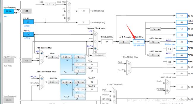
1.配置时钟(结合实际情况配置)
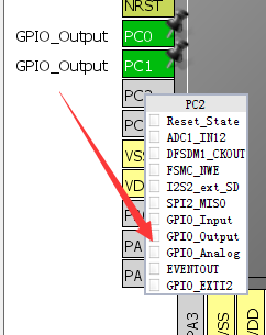
配置IO口为输出模式。
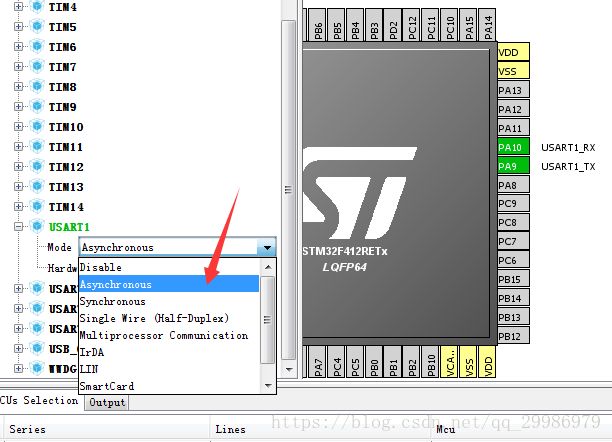
2.配置USART
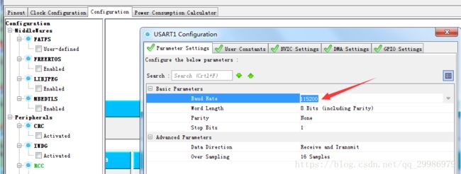
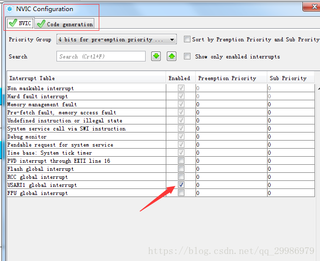
修改波特率和打开USART中断
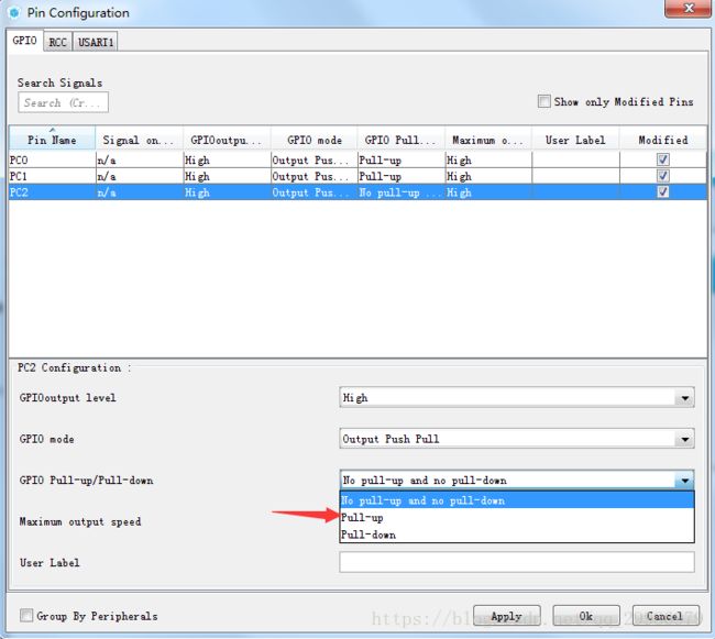
修改IO口输出模式为高速,上拉输出
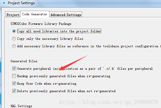
3.输出设置,选择对应的编译器
四.介绍程序的实现
1.USART的实现
uint8_t aRxBuffer[20];
uint8_t aTxStartMessages[] = "\r\nPlease enter 10 characters:\r\n";
HAL_UART_Transmit_IT(&huart1 ,(uint8_t*)aTxStartMessages,sizeof(aTxStartMessages)); //s发送
    HAL_UART_Receive_IT(&huart1,(uint8_t*)aRxBuffer,10);  //接收
void HAL_UART_RxCpltCallback(UART_HandleTypeDef *huart) //放在main()函数下面就可以,把接受到的内容回发
{
UNUSED(huart);
HAL_UART_Transmit(&huart1,(uint8_t*)aRxBuffer,10,0xFFFF);//(uint8_t*)aRxBuffer为字符串地址,10为字符串长度,0xFFFF为超时时间
} 2.IO口驱动外设
#define led0_1  HAL_GPIO_WritePin(GPIOC, GPIO_PIN_0, GPIO_PIN_SET)
#define led1_1  HAL_GPIO_WritePin(GPIOC, GPIO_PIN_1, GPIO_PIN_SET)//IO口高电平输出
#define led2_1  HAL_GPIO_WritePin(GPIOC, GPIO_PIN_2, GPIO_PIN_SET)//IO口高电平输出

#define led0_0  HAL_GPIO_WritePin(GPIOC, GPIO_PIN_0, GPIO_PIN_RESET)
#define led1_0  HAL_GPIO_WritePin(GPIOC, GPIO_PIN_1, GPIO_PIN_RESET)//IO口低电平输出
#define led2_0  HAL_GPIO_WritePin(GPIOC, GPIO_PIN_2, GPIO_PIN_RESET)//IO口高电平输出
3.延时函数
void Delay_Nus(uint32_t	t)//us延时
{
	uint8_t	i;
	while(t--)
	{
		i=25;
		while(i--);
	}
}
void Delay_Nms(uint32_t t)//ms延时
{
  while(t--)
  {
    Delay_Nus(1000);
  }
}
