在Unity的后处理shader中通过屏幕像素坐标和深度贴图反推世界坐标
要通过屏幕像素坐标反推世界坐标,就要知道世界坐标是如何变换为屏幕坐标的。理论上,将世界坐标(x, y, z)变换为(u, v, d)的过程如下:
第一步,将坐标点(x, y, z, 1)乘以从世界坐标系到相机坐标系的转换矩阵(World-to-Camera 4x4 Matrix),将坐标点(x, y, z, 1)变换为相机空间(Camera Space)坐标,转换后的坐标为(x1, y1, z1, w1),其中w1 = 1。
第二步,将相机空间坐标乘以从相机坐标系到裁剪空间(Clipping Space)坐标系的投影矩阵(Projection 4x4 Matrix),将坐标点转换到裁剪空间,转换后的坐标为(x2, y2, z2, w2),其中w2 = -z1。在Unity中,如果坐标点位于视锥体内(z1 > 0),那么x2,y2的范围都是[-z1, z1],z2的范围是[-z1, 0]。也就是说,我们可以想象这一步是将视锥体“压扁”成一个半立方体。
第三步,将裁剪空间中的坐标(x2, y2, z2, w2)除以w2,得到一个归一化的坐标(x3, y3, z3, 1),也就是说,x3, y3的范围是[-1, 1],z3的范围是[0, 1]。 根据摄像机投影的屏幕区域(通常是整个屏幕)和x3, y3,就可以得知这个坐标点在屏幕上的位置。z3则是深度。
投影矩阵的推导可参见:http://www.songho.ca/opengl/gl_projectionmatrix.html
关于裁剪空间可参见:https://www.scratchapixel.com/lessons/3d-basic-rendering/perspective-and-orthographic-projection-matrix/projection-matrix-GPU-rendering-pipeline-clipping
注意上面两篇文章里描述的裁剪空间的z2范围是[-z1, z1],最后得出的归一化坐标的z3的范围也是[-1, 1],这和我在Unity中的实验结果有所不同。
根据以上步骤,假如我们在后处理shader中能够拿到一个像素的归一化坐标(包括深度),并且得知w2,那就可以一步一步反推出世界坐标:先将归一化坐标乘以w2转换到裁剪空间,再乘以投影矩阵的逆转换回相机空间,最后再乘以世界坐标系到相机坐标系的转换矩阵的逆——也就是相机坐标系到世界坐标系的转换矩阵,就反推出了世界坐标。
不过实际在Unity的后处理shader中,我们往往只能拿到像素的归一化坐标,拿不到w2。因此我们要用另外的办法。一般我们在后处理shader中,能拿到的是x3, y3, z3,屏幕的高宽,以及相机的near, far和Field of View(FOV)。有了这些信息,我们就有办法将屏幕坐标直接变换到相机空间的坐标,而无需得知w2和投影矩阵的逆。
后处理shader的代码如下:
Shader "Custom/CalcWorldPosByDepthUseDepthTexInPostProcess" {
    Properties {
        _MainTex ("Base (RGB)", 2D) = "white" {}
    }
    SubShader {
        Tags { "RenderType"="Opaque" }
        LOD 200

        Pass{
            CGPROGRAM

            #include "UnityCG.cginc"
            #pragma vertex vert_img
            #pragma fragment frag

            sampler2D _CameraDepthTexture;

            float4 GetWorldPositionFromDepthValue( float2 uv, float linearDepth )
            {
                float camPosZ = _ProjectionParams.y + (_ProjectionParams.z - _ProjectionParams.y) * linearDepth;

                // unity_CameraProjection._m11 = near / t,其中t是视锥体near平面的高度的一半。
                // 投影矩阵的推导见:http://www.songho.ca/opengl/gl_projectionmatrix.html。
                // 这里求的height和width是坐标点所在的视锥体截面(与摄像机方向垂直)的高和宽,并且
                // 假设相机投影区域的宽高比和屏幕一致。
                float height = 2 * camPosZ / unity_CameraProjection._m11;
                float width = _ScreenParams.x / _ScreenParams.y * height;

                float camPosX = width * uv.x - width / 2;
                float camPosY = height * uv.y - height / 2;
                float4 camPos = float4(camPosX, camPosY, camPosZ, 1.0);
                return mul(unity_CameraToWorld, camPos);
            }

            float4 frag( v2f_img o ) : COLOR
            {
                float rawDepth =  SAMPLE_DEPTH_TEXTURE( _CameraDepthTexture, o.uv );
                // 注意:经过投影变换之后的深度和相机空间里的z已经不是线性关系。所以要先将其转换为线性深度。
                // 见:https://developer.nvidia.com/content/depth-precision-visualized
                float linearDepth = Linear01Depth(rawDepth);
                float4 worldpos = GetWorldPositionFromDepthValue( o.uv, linearDepth );
                return float4( worldpos.xyz / 255.0 , 1.0 ) ;  // 除以255以便显示颜色,测试用。
            }
            ENDCG
        }
    }
}
在上面的代码中,frag函数中的o.uv是将取值范围转换到[0, 1]后的x3, y3。_CameraDepthTexture即深度贴图,里面存储的就是每个像素点的z3。为了使用深度贴图,需要在C#脚本中将相机的depthTextureMode 为Depth或者DepthNormal:
MyCamera.depthTextureMode = DepthTextureMode.Depth; //使用相机自己生成的 _CameraDepthTexture 必须设置这个unity_CameraProjection是相机的投影矩阵,里面的第2行第2个元素存储的就是相机FOV的一半的正切值(tan)。
如何测试计算结果的正确性呢?我们可以在物体自身的材质上写一个shader,像后处理shader一样根据世界坐标显示物体的颜色:
Shader "Custom/GenerateDepthAndShowWoldPos" {
    Properties {
    }
    SubShader {
        Tags { "RenderType"="Opaque" }
        LOD 200
        Blend  Off


        Pass{
            CGPROGRAM

            #include "UnityCG.cginc"
            #pragma vertex vert
            #pragma fragment frag


            struct v2f {
                float4 pos: SV_POSITION;
                float4 worldpos : TEXCOORD0;
            };

            v2f vert( appdata_img v )
            {
                v2f o;
                o.pos = mul( UNITY_MATRIX_MVP,  v.vertex ) ;
                o.worldpos = mul(unity_ObjectToWorld, v.vertex);
                o.worldpos.w = o.pos.z / o.pos.w;
                return o;
            }

            float4 frag( v2f o ) : COLOR
            {
                return float4( o.worldpos.xyz / 255.0, 1.0) ; // o.worldpos.xyz/255 是为了颜色输出。
            }

            ENDCG
        }
    }
    FallBack "Diffuse"
}
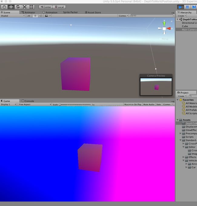
我们知道Unity编辑器的Scene视图是没有后处理效果的,而在编辑器中运行游戏时的Game视图是有后处理效果的。因此如果Scene和Game视图中的物体颜色一致,那就说明后处理反推世界坐标的逻辑写对了:
在上图的Game视图中,物体以外的背景呈现彩色,是因为后处理shader会处理屏幕上的所有像素并反推其世界坐标。不在物体上的像素全都会被映射到视锥体的far截面上。
注:实验用的Unity版本是5.5.0p4。本文参考了前同事的一篇笔记:http://note.youdao.com/share/?id=7350142fadd3b244a80df594ddfbb9f2&type=note#/
