【龙芯1c库】封装串口接口和使用示例
龙芯1c库是把龙芯1c的常用外设的常用功能封装为一个库,类似于STM32库。本文先讲解了龙芯1c库中的串口相关的函数,然后是如何利用这些函数实现串口通信。比如在串口打印helloworld,实现串口echo(即收到什么原封不动的发送回去),如何实现printf。再后是简单介绍一下龙芯1c的串口,最后是讨论一下串口相关的接口函数时如何封装的。
龙芯1c库的git地址是https://gitee.com/caogos/OpenLoongsonLib1c
龙芯1c库中串口接口使用示例
串口接口简介
先来看下串口头文件中提供哪些函数,头文件ls1c_uart.h源码如下
// 串口相关头文件


#ifndef __OPENLOONGSON_UART_H
#define __OPENLOONGSON_UART_H


// 串口模块编号
typedef enum
{
    LS1C_UART00 = 0,        // 全功能串口UART0可以分为两个四线串口UART00和UART01
    LS1C_UART01,
    LS1C_UART1,
    LS1C_UART2,
    LS1C_UART3,
    LS1C_UART4,
    LS1C_UART5,
    LS1C_UART6,
    LS1C_UART7,
    LS1C_UART8,
    LS1C_UART9,
    LS1C_UART10,
    LS1C_UART11
}ls1c_uart_t;


// 串口信息
typedef struct
{
    ls1c_uart_t UARTx;              // 串口模块编号
    unsigned int baudrate;          // 波特率
    BOOL rx_enable;                 // 是否需要使用串口接收数据(使能接收中断),发送默认使能
}ls1c_uart_info_t;


/*
 * 获取指定串口模块的基地址
 * @UARTx 串口编号
 * @ret 基地址
 */
inline void *uart_get_base(ls1c_uart_t UARTx);


/*
 * 初始化指定的串口模块
 * @uart_info_p 串口模块信息
 */
void uart_init(ls1c_uart_info_t *uart_info_p);


/*
 * 初始化串口2
 */
void uart2_init(void);


/*
 * 在串口2上打印字符串
 * @str 待打印的字符串
 */
void uart2_print(const char *str);


/*
 * 在调试串口打印字符串
 * @str 待打印的字符串
 */
void uart_debug_print(const char *str);


/*
 * 在调试串口打印一个字符
 * @ch 待打印的字符
 */
void uart_debug_putc(unsigned char ch);


/*
 * 把中断号转换为串口号
 * @IRQn 中断号
 * @ret 串口号
 */
inline ls1c_uart_t uart_irqn_to_uartx(int IRQn);


/*
 * 发送一个字节
 * @uartx 串口号
 * @ch 待发送的字符串
 */
void uart_putc(ls1c_uart_t uartx, unsigned char ch);


/*
 * 打印一个字符串到指定串口
 * @uartx 串口号
 * @str 待打印的字符串
 */
void uart_print(ls1c_uart_t uartx, const char *str);


#endif一般来说,只需要先调用uart_init()对指定串口初始化,并调用函数pin_set_remap()设置引脚复用,然后即可调用uart_putc()或者uart_print()发送。如果需要接收数据的话,需要调用irq_install()设置中断处理函数,并调用irq_enable()使能相应中断。最后实现中断处理函数即可。
因为我使用的板子是把串口2作为调试串口的,所以头文件中还出现了几个串口2相关的函数。
测试用例
为了进一步演示如何使用这些接口函数,设计了以下几个测试用例。
在串口上打印helloworld
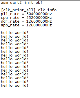
这里以调试串口2为例,在串口2上打印helloworld。代码不多,这里直接贴代码
/*
 * 初始化串口2
 */
void uart2_init(void)
{
    unsigned int tx_gpio = 37;
    unsigned int rx_gpio = 36;

    // 设置复用
    pin_set_remap(tx_gpio, PIN_REMAP_SECOND);
    pin_set_remap(rx_gpio, PIN_REMAP_SECOND);

    // 初始化相关寄存器
    debug_uart_info.UARTx = LS1C_UART2;
    debug_uart_info.baudrate = 115200;
    debug_uart_info.rx_enable = FALSE;  // 调试串口只需要打印(发送)功能,不需要接收功能
    uart_init(&debug_uart_info);

    return ;
}

// 通过串口2打印helloworld
void test_uart2_print_helloworld(void)
{
    while (1)
    {
        uart2_print("hello world!\r\n");
        delay_s(1);
    }
}
运行结果如下
函数printf()
前面已经用函数uart2_print()打印了helloworld,函数printf()也可以打印字符串。那么函数uart2_print和printf()有什么异同?函数uart2_print()只有一个入参,入参是什么样打印出来的字符串就是什么样;而printf()可以有多个参数,入参可以直接是一个字符串,也可以是一个格式,然后后面跟各种参数,printf()内部会将这些参数按照指定的格式生成字符串,并打印出来。实际上,printf()内部最后会调用函数uart2_print()把格式化生成的字符串打印出来。函数printf()使用起来更灵活,一般都是使用函数printf()。
函数printf()是libc中的一个函数,另外专门有一篇有关libc的博文其中对printf有详细的讲解
《【龙芯1c库】移植标准c库libc(libm类似)》
http://blog.csdn.net/caogos/article/details/79551884
标准的libc中的函数printf()是将字符串打印到文件(描述符)中,而这里为了适合裸机编程,对其稍加改造。简单来说就是先调用函数vsprintf()按照入参指定的格式生成待打印的字符串,然后调用串口打印函数uart_debug_print()打印到调试串口上。源码如下
#include
#include
#include "../lib/ls1c_uart.h"


#define PRINTF_BUF_SIZE                 (512)

int printf (const char *fmt, ...)
{
    int     len;
    va_list ap;
    char    buf[PRINTF_BUF_SIZE];

    va_start(ap, fmt);

    // 格式化字符串
    len = vsprintf (buf, fmt, ap);

    // 调用龙芯1c库中的串口函数打印字符串
    uart_debug_print(buf);

    va_end(ap);

    return (len);
} 串口初始化那部分代码是一样的,只是打印的函数调用printf()即可,测试代码如下
// 测试printf()函数
void test_printf(void)
{
    int i = 0;

    printf("[%s] hello!\r\n", __FUNCTION__);

    while (1)
    {
        printf("[%s] %d\r\n", __FUNCTION__, i++);
        delay_s(1);
    }
}
串口的收发(串口echo,收到什么原封不动发送回去)
有些时候不但需要串口发送一些数据,还需要从串口接收数据。实现串口echo是一个非常不错的测试用例,即在串口收到什么就原封不动的发送回去,这既能验证串口的收和发,同时测试程序也不会太复杂。
前面打印字符串用的是uart2_print()或者printf(),而这里则用uart_putc(),函数uart_putc()每次只发送一个字符。
串口接收一般采用中断形式,这里也以中断接收为例来讲解,但是发送还是查询方式。
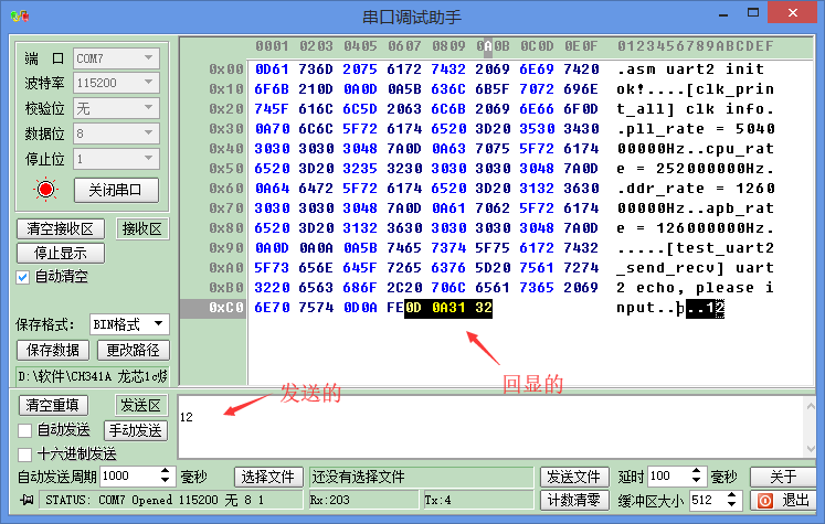
测试串口2的收发
和前面只打印相比,在初始化串口的时候需要打开中断,设置中断处理函数并实现中断处理函数。
串口测试代码如下
/*
 * 测试串口2的收发功能是否正常
 */
void test_uart2_send_recv(void)
{
    unsigned int tx_gpio = 37;
    unsigned int rx_gpio = 36;
    ls1c_uart_info_t uart2_info = {0};

    printf("\n\n[%s] uart2 echo, please input\r\n", __FUNCTION__);

    // 设置复用
    pin_set_remap(tx_gpio, PIN_REMAP_SECOND);
    pin_set_remap(rx_gpio, PIN_REMAP_SECOND);

    // 重新初始化串口2(使能接收中断)
    uart2_info.UARTx    = LS1C_UART2;
    uart2_info.baudrate = 115200;
    uart2_info.rx_enable= TRUE;         // 使能接收中断
    uart_init(&uart2_info);

    // 设置中断处理函数
    irq_install(LS1C_UART2_IRQ, test_uart_irqhandler, NULL);
    irq_enable(LS1C_UART2_IRQ);

    while (1)
    {
        delay_s(1);
    }
}
重点放在中断处理函数是如何实现的。先看源码吧
/*
 * 串口的中断处理函数
 * 如有需要,可以给每个串口单独写个中断处理函数,或者通过入参"中断号"来区分串口,并单独处理
 * @IRQn 中断号
 * @param 传递给中断处理函数的参数
 */
void test_uart_irqhandler(int IRQn, void *param)
{
    ls1c_uart_t uartx = uart_irqn_to_uartx(IRQn);
    void *uart_base = uart_get_base(uartx);
    unsigned char iir = reg_read_8(uart_base + LS1C_UART_IIR_OFFSET);

    // 判断是否为接收超时或接收到有效数据
    if ((IIR_RXTOUT & iir) || (IIR_RXRDY & iir))
    {
        // 是,则读取数据,并原样发送回去
        while (LSR_RXRDY & reg_read_8(uart_base + LS1C_UART_LSR_OFFSET))
        {
            uart_putc(uartx, reg_read_8(uart_base + LS1C_UART_DAT_OFFSET));
        }
    }

    return ;
}首先,调用uart_irqn_to_uartx()将中断号转换为串口号,这样做的目的是——不同的串口使用相同的中断处理函数。这里偷了个懒,实际使用中可能每个串口接不同的设备,可能需要对接收到的数据做不同的处理,如果那样的话,最好还是每个串口单独写一个中断处理函数。
然后,调用uart_get_base()获取串口的基地址,读取IIR寄存器的值。
然后,再判断是否为接收中断。龙芯1c的串口中断有多种,所以需要先判断一下是否为接收中断,接收中断又有两种形式:接收超时和接收到有效数据。
然后,就是把接收缓存中的数据,逐个读出来,并原封不动的发送回去。
测试结果如下
测试串口1的收发
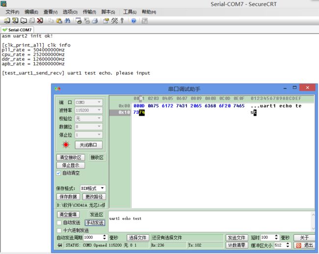
串口1和前面的串口2类似,采用同一个中断处理函数,测试函数如下
/*
 * 测试串口1的收发功能是否正常
 */
void test_uart1_send_recv(void)
{
    // EJTAG引脚复用比较特殊,除了需要设置复用寄存器外,
    // 还需要把引脚JTAG_SEL(注意,不是EJTAG_SEL)拉高,可能板子上有个跳线帽,注意观察
    unsigned int tx_gpio = 3;   // EJTAG_TDO/GPIO03
    unsigned int rx_gpio = 2;   // EJTAG_TDI/GPIO02
    ls1c_uart_info_t uart1_info = {0};

    printf("[%s] uart1 test echo. please input\r\n", __FUNCTION__);

    // 设置复用
    pin_set_remap(tx_gpio, PIN_REMAP_FOURTH);
    pin_set_remap(rx_gpio, PIN_REMAP_FOURTH);

    // 初始化串口
    uart1_info.UARTx    = LS1C_UART1;
    uart1_info.baudrate = 115200;
    uart1_info.rx_enable= TRUE;
    uart_init(&uart1_info);

    // 设置中断处理函数
    irq_install(LS1C_UART1_IRQ, test_uart_irqhandler, NULL);
    irq_enable(LS1C_UART1_IRQ);

    while (1)
    {
        delay_s(1);
    }
}
测试结果如下

测试串口3的收发
串口3也类似,测试函数如下
// 测试串口3的收发功能是否正常
void test_uart3_send_recv(void)
{
    // EJTAG引脚复用比较特殊,除了需要设置复用寄存器外,
    // 还需要把引脚JTAG_SEL(注意,不是EJTAG_SEL)拉高,可能板子上有个跳线帽,注意观察
    unsigned int tx_gpio = 1;   // EJTAG_TCK/GPIO01
    unsigned int rx_gpio = 0;   // EJTAG_SEL/GPIO00
    ls1c_uart_info_t uart3_info = {0};

    printf("[%s] uart3 test echo. please input\r\n", __FUNCTION__);

    // 设置复用
    pin_set_remap(tx_gpio, PIN_REMAP_FOURTH);
    pin_set_remap(rx_gpio, PIN_REMAP_FOURTH);

    // 初始化串口
    uart3_info.UARTx    = LS1C_UART3;
    uart3_info.baudrate = 115200;
    uart3_info.rx_enable= TRUE;
    uart_init(&uart3_info);

    // 设置中断处理函数
    irq_install(LS1C_UART3_IRQ, test_uart_irqhandler, NULL);
    irq_enable(LS1C_UART3_IRQ);

    // 通过串口3先发送一个字符串,用于单独判断发送功能是否正常
    uart_print(LS1C_UART3, "uart3 send\r\n");

    while (1)
    {
        delay_s(1);
        printf("[%s] ......\r\n", __FUNCTION__);
    }
}
测试结果如下

测试串口8的收发
串口8也类似,需要注意的地方是
“龙芯1C300A没有串口8,龙芯1C300B才有串口5到串口11这几个串口”
本测试用例是在白菜板V2.1(cpu是1C300B)上测试的。
测试源码如下
// 测试串口8的收发功能是否正常,注意龙芯1C300A没有串口8,龙芯1C300B才有串口5到串口11这几个串口
void test_uart8_send_recv(void)
{
    unsigned int tx_gpio = 54;      // CAMDATA4/GPIO54/UART8_TX
    unsigned int rx_gpio = 55;      // CAMDATA5/GPIO55/UART8_RX
    ls1c_uart_info_t uart8_info = {0};

    printf("[%s] uart8 test echo. please input...\r\n", __FUNCTION__);

    // 设置引脚复用
    pin_set_remap(tx_gpio, PIN_REMAP_FIFTH);
    pin_set_remap(rx_gpio, PIN_REMAP_FIFTH);

    // 初始化串口
    uart8_info.UARTx    = LS1C_UART8;
    uart8_info.baudrate = 115200;
    uart8_info.rx_enable= TRUE;
    uart_init(&uart8_info);

    // 设置中断处理函数
    irq_install(LS1C_UART8_IRQ, test_uart_irqhandler, NULL);
    irq_enable(LS1C_UART8_IRQ);

    // 通过串口8先发送一个字符串,用于单独判断发送功能是否正常
    uart_print(LS1C_UART8, "uart8 send\r\n");

    while (1)
    {
        delay_s(1);
        printf("[%s] ......\r\n", __FUNCTION__);
    }
}
测试用的完整源码清单
Main.c
#include "../lib/ls1c_public.h"
#include "../lib/ls1c_irq.h"
#include "../lib/ls1c_gpio.h"
#include "../lib/ls1c_delay.h"
#include "../lib/ls1c_mipsregs.h"
#include "../lib/ls1c_uart.h"
#include "../lib/ls1c_sys_tick.h"
#include "../lib/ls1c_clock.h"
#include "../example/test_gpio.h"
#include "../example/test_pwm.h"
#include "../example/test_delay.h"
#include "../example/test_simulate_i2c.h"
#include "../example/test_timer.h"
#include "../example/test_fpu.h"
#include "../example/test_i2c.h"
#include "../example/test_uart.h"
#include "../example/test_sys_tick.h"
#include "../example/test_spi.h"


// pmon提供的打印接口
struct callvectors *callvec;


// 硬浮点初始化
void fpu_init(void)
{
    unsigned int c0_status = 0;
    unsigned int c1_status = 0;

    // 使能协处理器1--FPU
    c0_status = read_c0_status();
    c0_status |= (ST0_CU1 | ST0_FR);
    write_c0_status(c0_status);

    // 配置FPU
    c1_status = read_c1_status();
    c1_status |= (FPU_CSR_FS | FPU_CSR_FO | FPU_CSR_FN);    // set FS, FO, FN
    c1_status &= ~(FPU_CSR_ALL_E);                          // disable exception
    c1_status = (c1_status & (~FPU_CSR_RM)) | FPU_CSR_RN;   // set RN
    write_c1_status(c1_status);

    return ;
}


void bsp_init(void)
{
    // 初始化调试串口
    uart2_init();

    // 硬浮点初始化
    fpu_init();

    // 初始化异常
    exception_init();

    // 显示时钟信息
    clk_print_all();

    return ;
}


int main(void)
{
    bsp_init();

    // -------------------------测试gpio----------------------
    /*
     * 测试库中gpio作为输出时的相关接口
     * led闪烁10次
     */
//    test_gpio_output();

    /*
     * 测试库中gpio作为输入时的相关接口
     * 按键按下时,指示灯点亮,否则,熄灭
     */
//    test_gpio_input();

    /*
     * 测试库中外部中断(gpio输入中断)的相关接口
     * 按键被按下后,会产生一个中断
     */
//    test_gpio_key_irq();


    // ------------------------测试串口-----------------------
    // 通过串口2打印helloworld
    test_uart2_print_helloworld();

    // 测试串口2的收发功能是否正常
//    test_uart2_send_recv();

    // 测试串口2的收发功能是否正常
//    test_uart1_send_recv();

    // 测试串口3的收发功能是否正常
//    test_uart3_send_recv();

    // 测试printf()函数
//    test_printf();


    // ------------------------测试PWM--------------------------------
    // 测试硬件pwm产生连续的pwm波形
//    test_pwm_normal();

    // 测试硬件pwm产生pwm脉冲
//    test_pwm_pulse();

    /*
     * 测试gpio04复用为pwm,gpio06作为普通gpio使用
     * PWM0的默认引脚位GPIO06,但也可以复用为GPIO04
     * 当gpio06还是保持默认为pwm时,复用gpio04为pwm0,那么会同时在两个引脚输出相同的pwm波形
     * 本函数旨在证明可以在gpio04复用为pwm0时,还可以将(默认作为pwm0的)gpio06作为普通gpio使用
     */
//    test_pwm_gpio04_gpio06();

    // 测试pwm最大周期
//    test_pwm_max_period();


    // ------------------------测试软件延时--------------------------------
    // 测试延时函数delay_1ms()
//    test_delay_1ms();

    // 测试延时函数delay_1us()
//    test_delay_1us();

    // 测试延时函数delay_1s()
//    test_delay_1s();


    // ------------------------测试模拟I2C------------------------------
    // 测试模拟I2C
//    test_simulate_i2c_am2320();

    // ------------------------测试硬件I2C---------------------------
    // 用温湿度传感器测试硬件i2c
//    test_i2c_am2320();


    // ------------------------测试硬件定时器---------------------------
    // 测试硬件定时器的定时功能(读取中断状态位的方式判断是否超时)
//    test_timer_poll_time_out();

    // 测试硬件定时器的中断
//    test_timer_irq();

    // 测试硬件定时器的计时
//    test_timer_get_time();

    // ------------------------测试硬浮点(FPU)---------------------------
    // 测试使用硬浮点进行浮点数的加减乘除
//    test_fpu();

    // ------------------------测试滴答定时器---------------------------
    // 通过获取当前tick值来测试滴答定时器,默认已经使能了滴答定时器,每秒1000个tick
//    test_sys_tick();


    // ------------------------测试硬件SPI---------------------------
    // 用tm7705测试硬件SPI
    // 具体为tm7705+ntc热敏电阻实现温度测量(3d打印机就可以采用此方案测量温度)
//    test_spi_tm7705();

    // ------------------------测试CAN---------------------------
    // 详情请参考文件test_can.c


    while (1)
        ;

	return(0);
}
test_uart.c
// 测试串口的源文件

#include "../lib/ls1c_public.h"
#include "../lib/ls1c_uart.h"
#include "../lib/start.h"
#include "../lib/ls1c_irq.h"
#include "../lib/ls1c_pin.h"
#include "../lib/ls1c_delay.h"


/*
 * 串口的中断处理函数
 * 如有需要,可以给每个串口单独写个中断处理函数,或者通过入参"中断号"来区分串口,并单独处理
 * @IRQn 中断号
 * @param 传递给中断处理函数的参数
 */
void test_uart_irqhandler(int IRQn, void *param)
{
    ls1c_uart_t uartx = uart_irqn_to_uartx(IRQn);
    void *uart_base = uart_get_base(uartx);
    unsigned char iir = reg_read_8(uart_base + LS1C_UART_IIR_OFFSET);

    // 判断是否为接收超时或接收到有效数据
    if ((IIR_RXTOUT & iir) || (IIR_RXRDY & iir))
    {
        // 是,则读取数据,并原样发送回去
        while (LSR_RXRDY & reg_read_8(uart_base + LS1C_UART_LSR_OFFSET))
        {
            uart_putc(uartx, reg_read_8(uart_base + LS1C_UART_DAT_OFFSET));
        }
    }

    return ;
}


/*
 * 测试串口2的收发功能是否正常
 */
void test_uart2_send_recv(void)
{
    unsigned int tx_gpio = 37;
    unsigned int rx_gpio = 36;
    ls1c_uart_info_t uart2_info = {0};

    printf("\n\n[%s] uart2 echo, please input\r\n", __FUNCTION__);

    // 设置复用
    pin_set_remap(tx_gpio, PIN_REMAP_SECOND);
    pin_set_remap(rx_gpio, PIN_REMAP_SECOND);

    // 重新初始化串口2(使能接收中断)
    uart2_info.UARTx    = LS1C_UART2;
    uart2_info.baudrate = 115200;
    uart2_info.rx_enable= TRUE;         // 使能接收中断
    uart_init(&uart2_info);

    // 设置中断处理函数
    irq_install(LS1C_UART2_IRQ, test_uart_irqhandler, NULL);
    irq_enable(LS1C_UART2_IRQ);

    while (1)
    {
        delay_s(1);
    }
}


/*
 * 测试串口1的收发功能是否正常
 */
void test_uart1_send_recv(void)
{
    // EJTAG引脚复用比较特殊,除了需要设置复用寄存器外,
    // 还需要把引脚JTAG_SEL(注意,不是EJTAG_SEL)拉高,可能板子上有个跳线帽,注意观察
    unsigned int tx_gpio = 3;   // EJTAG_TDO/GPIO03
    unsigned int rx_gpio = 2;   // EJTAG_TDI/GPIO02
    ls1c_uart_info_t uart1_info = {0};

    printf("[%s] uart1 test echo. please input\r\n", __FUNCTION__);

    // 设置复用
    pin_set_remap(tx_gpio, PIN_REMAP_FOURTH);
    pin_set_remap(rx_gpio, PIN_REMAP_FOURTH);

    // 初始化串口
    uart1_info.UARTx    = LS1C_UART1;
    uart1_info.baudrate = 115200;
    uart1_info.rx_enable= TRUE;
    uart_init(&uart1_info);

    // 设置中断处理函数
    irq_install(LS1C_UART1_IRQ, test_uart_irqhandler, NULL);
    irq_enable(LS1C_UART1_IRQ);

    while (1)
    {
        delay_s(1);
    }
}


// 测试串口3的收发功能是否正常
void test_uart3_send_recv(void)
{
    // EJTAG引脚复用比较特殊,除了需要设置复用寄存器外,
    // 还需要把引脚JTAG_SEL(注意,不是EJTAG_SEL)拉高,可能板子上有个跳线帽,注意观察
    unsigned int tx_gpio = 1;   // EJTAG_TCK/GPIO01
    unsigned int rx_gpio = 0;   // EJTAG_SEL/GPIO00
    ls1c_uart_info_t uart3_info = {0};

    printf("[%s] uart3 test echo. please input\r\n", __FUNCTION__);

    // 设置复用
    pin_set_remap(tx_gpio, PIN_REMAP_FOURTH);
    pin_set_remap(rx_gpio, PIN_REMAP_FOURTH);

    // 初始化串口
    uart3_info.UARTx    = LS1C_UART3;
    uart3_info.baudrate = 115200;
    uart3_info.rx_enable= TRUE;
    uart_init(&uart3_info);

    // 设置中断处理函数
    irq_install(LS1C_UART3_IRQ, test_uart_irqhandler, NULL);
    irq_enable(LS1C_UART3_IRQ);

    // 通过串口3先发送一个字符串,用于单独判断发送功能是否正常
    uart_print(LS1C_UART3, "uart3 send\r\n");

    while (1)
    {
        delay_s(1);
        printf("[%s] ......\r\n", __FUNCTION__);
    }
}

// 测试printf()函数
void test_printf(void)
{
    int i = 0;

    printf("[%s] hello!\r\n", __FUNCTION__);

    while (1)
    {
        printf("[%s] %d\r\n", __FUNCTION__, i++);
        delay_s(1);
    }
}


// 通过串口2打印helloworld
void test_uart2_print_helloworld(void)
{
    while (1)
    {
        uart2_print("hello world!\r\n");
        delay_s(1);
    }
}
test_uart.h
// 测试串口的头文件


#ifndef __OPENLOONGSON_TEST_UART_H
#define __OPENLOONGSON_TEST_UART_H


/*
 * 测试串口2的收发功能是否正常
 */
void test_uart2_send_recv(void);


/*
 * 测试串口1的收发功能是否正常
 */
void test_uart1_send_recv(void);


// 测试串口3的收发功能是否正常
void test_uart3_send_recv(void);


// 测试printf()函数
void test_printf(void);


// 通过串口2打印helloworld
void test_uart2_print_helloworld(void);


#endif
封装串口接口
我认为串口本身并不复杂,相关寄存器也只有几个,而linux等操作系统为了实现shell等,把本来简单的串口整的“好像很复杂的样子”。所以这里直接把1c库中串口相关函数的源码贴出来,代码不多,对照芯片手册,详细很快能看懂。
ls1c_uart.c
// 串口相关源码

#include
#include
#include "ls1c_public.h"
#include "ls1c_regs.h"
#include "ls1c_pin.h"
#include "ls1c_uart.h"
#include "ls1c_clock.h"
#include "start.h"
#include "ls1c_irq.h"


// 串口线路状态寄存器的位域
#define LS1C_UART_LSR_TE                (1 << 6)
#define LS1C_UART_LSR_TFE               (1 << 5)


// 打印缓存的大小
#define LS1C_UART_PRINT_BUF_SIZE        (256)


// 调试串口信息
ls1c_uart_info_t debug_uart_info = {0};


/*
 * 获取指定串口模块的基地址
 * @UARTx 串口编号
 * @ret 基地址
 */
inline void *uart_get_base(ls1c_uart_t UARTx)
{
    void *base = NULL;

    switch (UARTx)
    {
        case LS1C_UART00:
            base = (void *)LS1C_UART00_BASE;
            break;
        case LS1C_UART01:
            base = (void *)LS1C_UART01_BASE;
            break;

        case LS1C_UART1:
            base = (void *)LS1C_UART1_BASE;
            break;

        case LS1C_UART2:
            base = (void *)LS1C_UART2_BASE;
            break;

        case LS1C_UART3:
            base = (void *)LS1C_UART3_BASE;
            break;

        case LS1C_UART4:
            base = (void *)LS1C_UART4_BASE;
            break;

        case LS1C_UART5:
            base = (void *)LS1C_UART5_BASE;
            break;

        case LS1C_UART6:
            base = (void *)LS1C_UART6_BASE;
            break;

        case LS1C_UART7:
            base = (void *)LS1C_UART7_BASE;
            break;

        case LS1C_UART8:
            base = (void *)LS1C_UART8_BASE;
            break;

        case LS1C_UART9:
            base = (void *)LS1C_UART9_BASE;
            break;

        case LS1C_UART10:
            base = (void *)LS1C_UART10_BASE;
            break;

        case LS1C_UART11:
            base = (void *)LS1C_UART11_BASE;
            break;

        default:
            break;
    }

    return base;
}


/*
 * 初始化指定的串口模块
 * @uart_info_p 串口模块信息
 */
void uart_init(ls1c_uart_info_t *uart_info_p)
{
    void *uart_base = uart_get_base(uart_info_p->UARTx);
    unsigned long baudrate_div = 0;

    // 禁止所有中断
    reg_write_8(0,      uart_base + LS1C_UART_IER_OFFSET);

    // 接收FIFO的中断申请Trigger为14字节,清空发送和接收FIFO,并复位
    reg_write_8(0xc3,   uart_base + LS1C_UART_FCR_OFFSET);

    // 设置波特率
    reg_write_8(0x80,   uart_base + LS1C_UART_LCR_OFFSET);
    baudrate_div = clk_get_cpu_rate() / 16 / uart_info_p->baudrate / 2;
    reg_write_8((baudrate_div >> 8) & 0xff, uart_base + LS1C_UART_MSB_OFFSET);
    reg_write_8(baudrate_div & 0xff,        uart_base + LS1C_UART_LSB_OFFSET);

    // 8个数据位,1个停止位,无校验
    reg_write_8(0x03,   uart_base + LS1C_UART_LCR_OFFSET);

    // 使能接收中断
    if (TRUE == uart_info_p->rx_enable)
    {
        reg_write_8(IER_IRxE|IER_ILE , uart_base + LS1C_UART_IER_OFFSET);
    }

    return ;
}


/*
 * 判断FIFO是否为空
 * @uartx 串口号
 * @ret TRUE or FALSE
 */
BOOL uart_is_transmit_empty(ls1c_uart_t uartx)
{
    void *uart_base = uart_get_base(uartx);
    unsigned char status = reg_read_8(uart_base + LS1C_UART_LSR_OFFSET);

    if (status & (LS1C_UART_LSR_TE | LS1C_UART_LSR_TFE))
    {
        return TRUE;
    }
    else
    {
        return FALSE;
    }
}


/*
 * 发送一个字节
 * @uartx 串口号
 * @ch 待发送的字符串
 */
void uart_putc(ls1c_uart_t uartx, unsigned char ch)
{
    void *uart_base = uart_get_base(uartx);

    // 等待
    while (FALSE == uart_is_transmit_empty(uartx))
        ;

    // 发送
    reg_write_8(ch, uart_base + LS1C_UART_DAT_OFFSET);

    return ;
}


/*
 * 打印一个字符串到指定串口
 * @uartx 串口号
 * @str 待打印的字符串
 */
void uart_print(ls1c_uart_t uartx, const char *str)
{
    while ('\0' != *str)                // 判断是否为字符串结束符
    {
        uart_putc(uartx, *str);   // 发送一个字符
        str++;
    }

    return ;
}


/*
 * 初始化串口2
 */
void uart2_init(void)
{
    unsigned int tx_gpio = 37;
    unsigned int rx_gpio = 36;

    // 设置复用
    pin_set_remap(tx_gpio, PIN_REMAP_SECOND);
    pin_set_remap(rx_gpio, PIN_REMAP_SECOND);

    // 初始化相关寄存器
    debug_uart_info.UARTx = LS1C_UART2;
    debug_uart_info.baudrate = 115200;
    debug_uart_info.rx_enable = FALSE;  // 调试串口只需要打印(发送)功能,不需要接收功能
    uart_init(&debug_uart_info);

    return ;
}


/*
 * 在串口2上打印字符串
 * @str 待打印的字符串
 */
void uart2_print(const char *str)
{
    uart_print(LS1C_UART2, str);
    return ;
}


/*
 * 在调试串口打印字符串
 * @str 待打印的字符串
 */
void uart_debug_print(const char *str)
{
    uart_print(debug_uart_info.UARTx, str);
    return ;
}


/*
 * 在调试串口打印一个字符
 * @ch 待打印的字符
 */
void uart_debug_putc(unsigned char ch)
{
    uart_putc(debug_uart_info.UARTx, ch);
    return ;
}


/*
 * 把中断号转换为串口号
 * @IRQn 中断号
 * @ret 串口号
 */
inline ls1c_uart_t uart_irqn_to_uartx(int IRQn)
{
    ls1c_uart_t uartx = LS1C_UART2;

    switch (IRQn)
    {
        /* 串口UART00和UART01的中断号还待确定
        case LS1C_UART00_IRQ:
            uartx = LS1C_UART00;
            break;

        case LS1C_UART01_IRQ:
            uartx = LS1C_UART01;
            break;
       */

        case LS1C_UART1_IRQ:
            uartx = LS1C_UART1;
            break;

        case LS1C_UART2_IRQ:
            uartx = LS1C_UART2;
            break;

        case LS1C_UART3_IRQ:
            uartx = LS1C_UART3;
            break;

        case LS1C_UART4_IRQ:
            uartx = LS1C_UART4;
            break;

        case LS1C_UART5_IRQ:
            uartx = LS1C_UART5;
            break;

        case LS1C_UART6_IRQ:
            uartx = LS1C_UART6;
            break;

        case LS1C_UART7_IRQ:
            uartx = LS1C_UART7;
            break;

        case LS1C_UART8_IRQ:
            uartx = LS1C_UART8;
            break;

        case LS1C_UART9_IRQ:
            uartx = LS1C_UART9;
            break;

        case LS1C_UART10_IRQ:
            uartx = LS1C_UART10;
            break;

        case LS1C_UART11_IRQ:
            uartx = LS1C_UART11;
            break;

        default:
            uartx = LS1C_UART2;
            break;
    }

    return uartx;
}
ls1c_uart.h
// 串口相关头文件


#ifndef __OPENLOONGSON_UART_H
#define __OPENLOONGSON_UART_H


// 串口模块编号
typedef enum
{
    LS1C_UART00 = 0,        // 全功能串口UART0可以分为两个四线串口UART00和UART01
    LS1C_UART01,
    LS1C_UART1,
    LS1C_UART2,
    LS1C_UART3,
    LS1C_UART4,
    LS1C_UART5,
    LS1C_UART6,
    LS1C_UART7,
    LS1C_UART8,
    LS1C_UART9,
    LS1C_UART10,
    LS1C_UART11
}ls1c_uart_t;


// 串口信息
typedef struct
{
    ls1c_uart_t UARTx;              // 串口模块编号
    unsigned int baudrate;          // 波特率
    BOOL rx_enable;                 // 是否需要使用串口接收数据(使能接收中断),发送默认使能
}ls1c_uart_info_t;


/*
 * 获取指定串口模块的基地址
 * @UARTx 串口编号
 * @ret 基地址
 */
inline void *uart_get_base(ls1c_uart_t UARTx);


/*
 * 初始化指定的串口模块
 * @uart_info_p 串口模块信息
 */
void uart_init(ls1c_uart_info_t *uart_info_p);


/*
 * 初始化串口2
 */
void uart2_init(void);


/*
 * 在串口2上打印字符串
 * @str 待打印的字符串
 */
void uart2_print(const char *str);


/*
 * 在调试串口打印字符串
 * @str 待打印的字符串
 */
void uart_debug_print(const char *str);


/*
 * 在调试串口打印一个字符
 * @ch 待打印的字符
 */
void uart_debug_putc(unsigned char ch);


/*
 * 把中断号转换为串口号
 * @IRQn 中断号
 * @ret 串口号
 */
inline ls1c_uart_t uart_irqn_to_uartx(int IRQn);


/*
 * 发送一个字节
 * @uartx 串口号
 * @ch 待发送的字符串
 */
void uart_putc(ls1c_uart_t uartx, unsigned char ch);


/*
 * 打印一个字符串到指定串口
 * @uartx 串口号
 * @str 待打印的字符串
 */
void uart_print(ls1c_uart_t uartx, const char *str);


#endif更多更完整的代码,请移步到git查看。
感谢阅读!

