5G 38.300 Rel15 中文版
文章目录
- 38.300 NR; NR and NG-RAN Overall Description
- 1 范围
- 2 参考
- 3 缩略语和定义
- 4 整体架构和功能分裂
- 4.1整体架构
- 4.2 功能分割
- 4.3网络接口
- 4.4无线电协议架构
- 5 物理层
- 5.1波形,数字命理和框架结构
- 5.2下行
- 5.3上行
- 5.4载波聚合
- 5.5传输信道
- 6 层2
- 6.1概述
- 6.2 MAC子层
- 6.3 RLC子层
- 6.4 PDCP子层
- 6.5 SDAP子层
- 6.6 L2数据流
- 6.7载波聚合
- 6.8双连接
- 6.9补充上行链路
- 6.10带宽适应
- 7 RRC
- 7.1服务和职能
- 7.2协议状态
- 7.3系统信息处理
- 7.4访问控制
- 7.5 UE能力检索框架
- 7.6 NAS消息的传输
- 7.7 载波聚合
- 7.8带宽适应
- 8 NG 标识
- 9移动性和状态转变
- 9.1概述
- 9.2内部-NR
- 10 Scheduling
- 11 UE Power Saving
- 12 QoS
- 13 Security
- 14 UE Capabilities
- 15 Self-Configuration and Self-Optimisation
- 16 垂直支持
- Annex A (informative): QoS Handling in RAN
- Annex B (informative): Deployment Scenarios
3rd Generation Partnership Project;
Technical Specification Group Radio Access Network;
NR; NR and NG-RAN Overall Description;
Stage 2
(Release 15)
38.300 NR; NR and NG-RAN Overall Description
1 范围
本文档提供了NG-RAN的概述和总体描述,并侧重于连接到5GC的NR的无线电接口协议架构(连接到5GC的E-UTRA在36系列中有所涉及)。 无线电接口协议的细节在38系列的配套规范中规定。
2 参考
3 缩略语和定义
4 整体架构和功能分裂
4.1整体架构
NG-RAN节点是:
- gNB,向UE提供NR用户平面和控制平面协议终端; 要么
- ng-eNB,向UE提供E-UTRA用户平面和控制平面协议终端。
gNB和ng-eNB通过Xn接口相互连接。 gNB和ng-eNB也通过NG接口连接到5GC,更具体地通过NG-C接口连接到AMF(接入和移动管理功能),并通过NG-U接口连接到UPF(用户平面功能)。 NG-U接口(参见3GPP TS 23.501 [3])。
注意:功能划分的体系结构和F1接口在3GPP TS 38.401 [4]中定义。
NG-RAN架构如下图4.1-1所示。

4.2 功能分割
gNB和ng-eNB承载以下功能:
- 用于无线电资源管理的功能:无线电承载控制,无线电接纳控制,连接移动性控制,在上行链路和下行链路中向UE的动态资源分配(调度);
- 数据的IP头压缩,加密和完整性保护;
- 当不能从UE提供的信息确定到AMF的路由时,在UE附着处选择AMF;
- 用户平面数据向UPF的路由;
- 控制平面信息向AMF的路由;
- 连接设置和释放;
- 调度和传输寻呼消息(源自AMF);
- 调度和传输系统广播信息(源自AMF或O&M);
- 移动和调度的测量和测量报告配置;
- 上行链路中的传输级分组标记;
- 会话管理;
- 支持网络切片;
- QoS流量管理和映射到数据无线电承载;
- 支持处于RRC_INACTIVE状态的UE;
- NAS消息的分发功能;
- 无线接入网络共享;
- 双连接;
- NR和E-UTRA之间的紧密互通。
AMF承载以下主要功能(参见3GPP TS 23.501 [3]):
- NAS信令终止;
- NAS信令安全;
- AS安全控制;
- 用于3GPP接入网络之间的移动性的CN间节点信令;
- 空闲模式UE可达性(包括寻呼重传的控制和执行);
- 注册区管理;
- 支持系统内和系统间的移动性;
- 访问认证;
- 访问授权,包括检查漫游权;
- 移动管理控制(订阅和政策);
- 支持网络切片;
- SMF选择。
UPF承载以下主要功能(参见3GPP TS 23.501 [3]):
- 内/内RAT移动性的锚点(适用时);
- 与数据网络互连的外部PDU会话点;
- 分组路由和转发;
- 数据包检查和用户平面部分的策略规则实施;
- 交通使用情况报告;
- 上行链路分类器,支持将流量路由到数据网络;
- 分支点以支持多宿主PDU会话;
- 用户平面的QoS处理,例如,包过滤,门控,UL / DL速率执行;
- 上行链路流量验证(SDF到QoS流量映射);
- 下行链路分组缓冲和下行链路数据通知触发。
会话管理功能(SMF)承载以下主要功能(参见3GPP TS 23.501 [3]):
- 会话管理;
- UE IP地址分配和管理;
- 选择和控制UP功能;
- 配置UPF的交通转向,将交通路由到正确的目的地;
- 控制政策执行和QoS的一部分;
- 下行链路数据通知。
这在下图中总结,其中黄色框表示逻辑节点,白框表示主要功能。
4.3网络接口
4.3.1 NG接口
4.3.1.1 NG用户平面
NG用户平面接口(NG-U)在NG-RAN节点和UPF之间定义。 NG接口的用户面协议栈如图4.3.1.1-1所示。传输网络层建立在IP传输上,GTP-U用于UDP / IP之上,以承载NG-RAN节点和UPF之间的用户平面PDU。

NG-U在NG-RAN节点和UPF之间提供无保证的用户平面PDU传送。
NG-U的更多细节可以在3GPP TS 38.410 [16]中找到。
4.3.1.2 NG控制平面
NG控制平面接口(NG-C)在NG-RAN节点和AMF之间定义。 NG接口的控制平面协议栈如图4.3.1.2-1所示。传输网络层建立在IP传输之上。为了可靠地传输信令消息,在IP之上添加SCTP。应用层信令协议称为NGAP(NG应用协议)。 SCTP层提供有保证的应用层消息传递。在传输中,IP层点对点传输用于传递信令PDU。

NG-C提供以下功能:
- NG接口管理;
- UE上下文管理;
- UE移动性管理;
- 传输NAS消息;
- 寻呼;
- PDU会话管理;
- 配置转移;
- 警告信息传输。
NG-C的更多细节可以在3GPP TS 38.410 [16]中找到。
4.3.2 Xn接口
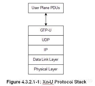
4.3.2.1 Xn用户平面
Xn用户平面(Xn-U)接口在两个NG-RAN节点之间定义。 Xn接口上的用户平面协议栈如图4.3.2.1-1所示。传输网络层建立在IP传输上,GTP-U用于UDP / IP之上以承载用户平面PDU。
Xn-U提供无保证的用户平面PDU传输,并支持以下功能:
- 数据转发;
- 流量控制。
Xn-U的更多细节可以在3GPP TS 38.420 [17]中找到。
4.3.2.2 Xn控制平面
Xn控制平面接口(Xn-C)在两个NG-RAN节点之间定义。 Xn接口的控制平面协议栈如图4.3.2.2-1所示。传输网络层建立在IP之上的SCTP上。应用层信令协议称为XnAP(Xn应用协议)。 SCTP层提供有保证的应用层消息传递。在传输IP层中,点对点传输用于传递信令PDU。

Xn-C接口支持以下功能:
- Xn接口管理;
- UE移动性管理,包括上下文传送和RAN寻呼:
- 双连接。
Xn-C的更多细节可以在3GPP TS 38.420 [17]中找到。
4.4无线电协议架构
4.4.1用户平面
下图显示了用户平面的协议栈,其中SDAP,PDCP,RLC和MAC子层(在网络侧的gNB中终止)执行子条款6中列出的功能。

4.4.2控制平面
下图显示了控制平面的协议栈,其中:
- PDCP,RLC和MAC子层(在网络侧的gNB中终止)执行子条款6中列出的功能;
- RRC(在网络侧的gNB中终止)执行子条款7中列出的功能;
- NAS控制协议(在网络侧的AMF中终止)执行3GPP TS 23.501 [3]中列出的功能,例如:身份验证,移动性管理,安全控制…

4.5多RAT双连接
NG-RAN支持多RAT双连接(MR-DC)操作,其中RRC_CONNECTED中的UE被配置为利用由两个不同调度器提供的无线电资源,这两个调度器位于通过非理想回程连接的两个不同NG-RAN节点中并且提供E-UTRA(即,如果节点是ng-eNB)或NR接入(即,如果节点是gNB)。 MR-DC操作的更多细节可以在3GPP TS 37.340 [6]中找到。
5 物理层
5.1波形,数字命理和框架结构
下行链路传输波形是使用循环前缀的传统OFDM。上行链路传输波形是使用循环前缀的常规OFDM,其中变换预编码功能执行可以被禁用或启用的DFT扩展。

数字命理基于指数可扩展的子载波间隔f =2μ×15 kHz,其中μ= {0,1,3,4}用于PSS,SSS和PBCH,μ= {0,1,2,3}用于其他信道。所有子载波间隔均支持正常CP,μ= 2支持扩展CP。 12个连续的子载波形成物理资源块(PRB)。运营商最多支持275个PRB。

UE配置有载波带宽部分,其定义UE在小区的操作带宽内的操作带宽。对于初始接入,并且直到接收到UE在小区中的配置,使用从系统信息检测到的初始带宽部分。 UE可以配置有若干载波带宽部分,其中只有一个可以在给定的分量载波上是活动的。
下行链路和上行链路传输被组织成具有10ms持续时间的帧,由10个1ms子帧组成。每帧被分成两个大小相等的半帧,每个半帧有五个子帧。
定时提前TA用于相对于下行链路帧定时调整上行链路帧定时

基本传输单元是一个slot。时隙持续时间是具有正常CP的14个符号和具有扩展CP的12个符号,并且作为所使用的子载波间隔的函数在时间上缩放。
FDD和TDD都受支持。
5.2下行
5.2.1下行传输方案
PDSCH支持基于闭环DMRS的空间复用。最多支持8个和12个正交DL DMRS端口,分别支持类型1和类型2 DMRS。对于SU-MIMO,每个UE最多支持8个正交DL DMRS端口,并且MU-MIMO支持每个UE多达4个正交DL DMRS端口。 SU-MIMO码字的数量是1-4层传输的数量,而5-8层传输的数量是2。
使用相同的预编码矩阵发送DMRS和对应的PDSCH,并且UE不需要知道预编码矩阵来解调传输。发射机可以对传输带宽的不同部分使用不同的预编码器矩阵,从而产生频率选择性预编码。 UE还可以假设在表示预编码资源块组(PRG)的一组PRB上使用相同的预编码矩阵。
5.2.2物理下行共享信道的物理层处理
传输信道的下行物理层处理包括以下步骤:
- 传输块CRC附件(3824以上的TBS具有24位CRC,否则为16位CRC);
- 代码块分段和代码块CRC附件(24位CRC);
- 信道编码:LDPC编码(基本图#1或基本图#2);
- 物理层混合ARQ处理和速率匹配;
- 位交织;
- 调制:QPSK,16QAM,64QAM和256QAM;
- 层映射和预编码;
- 映射到分配的资源和天线端口。
UE可以假设在其中将PDSCH发送到UE的每个层上存在具有解调参考信号的至少一个符号。 DMRS符号和资源元素映射的数量由更高层配置。
可以在附加符号上发送相位跟踪RS以帮助接收机相位跟踪。
DL-SCH物理层模型在3GPP TS 38.202 [20]中描述。
5.2.3物理下行链路控制信道
UE特定的物理下行链路控制信道(PDCCH)用于调度PDSCH上的DL传输和PUSCH上的UL传输。 PDCCH上的下行链路控制信息(DCI)包括:
- 至少包含调制和编码格式,资源分配以及与DL-SCH相关的混合ARQ信息的下行链路指配;
- 上行链路调度许可至少包含与UL-SCH相关的调制和编码格式,资源分配和混合ARQ信息。
控制信道由控制信道元素的聚合形成,每个控制信道元素由一组资源元素组组成。通过聚合不同数量的控制信道元素来实现控制信道的不同码率。
极化编码用于PDCCH。
承载PDCCH的每个资源元素组携带其自己的DMRS。
QPSK调制用于PDCCH。
5.2.4同步信号和PBCH
同步信号和PBCH块由主要和次要同步信号(PSS,SSS)组成,每个信号占用1个符号和127个子载波,PBCH跨越3个OFDM符号和240个子载波,但是在一个符号上留下未使用的部分在中间用于SSS如图5.2.4-1所示。可以由网络配置SS / PBCH块的周期性,并且可以通过子载波间隔确定可以发送SS / PBCH块的时间位置。

极化编码用于PBCH。
UE可以假设SS / PBCH块的频带特定子载波间隔,除非网络已经将UE配置为采用不同的子载波间隔。
PBCH符号携带其自己的频率复用DMRS。
QPSK调制用于PBCH。
PBCH物理层模型在3GPP TS 38.202 [20]中描述。
5.2.5物理层程序
5.2.5.1链路适配
具有各种调制方案和信道编码率的链路自适应(AMC:自适应调制和编码)被应用于PDSCH。相同的编码和调制应用于属于在一个TTI内和在MIMO码字内调度给一个用户的相同L2 PDU的所有资源块组。
对于信道状态估计目的,UE可以被配置为测量CSI-RS并基于CSI-RS测量来估计下行链路信道状态。 UE将估计的信道状态反馈给gNB以用于链路自适应。
5.2.5.2功率控制
可以使用下行链路功率控制。
5.2.5.3小区搜索
小区搜索是UE获取与小区的时间和频率同步并检测该小区的小区ID的过程。 NR小区搜索基于主同步信号和辅助同步信号以及PBCH DMRS。
5.2.5.4 HARQ
支持异步增量冗余混合ARQ。 gNB在DCI中动态地或在RRC配置中半静态地向UE提供HARQ-ACK反馈定时。
5.3上行
5.3.1上行传输方案
PUSCH支持两种传输方案:基于码本的传输和基于非码本的传输。
对于基于码本的传输,gNB在DCI中向UE提供发送预编码矩阵指示。 UE使用该指示从码本中选择PUSCH发送预编码器。对于基于非码本的传输,UE基于来自DCI的宽带SRI字段确定其PUSCH预编码器。
PUSCH支持基于闭环DMRS的空间复用。对于具有CP-OFDM的SU-MIMO,支持多达4层传输。 SU-MIMO码字的数量是一个。当使用变换预编码时,仅支持单个MIMO层传输。
5.3.2物理上行共享信道的物理层处理
传输信道的上行链路物理层处理包括以下步骤:
- 传输块CRC附件(3824以上的TBS具有24位CRC,否则为16位CRC);
- 码块分段和码块CRC附件(24位CRC);
- 信道编码:LDPC编码(基本图#1或基本图#2);
- 位交织;
- 调制:Pi / 2 BPSK(仅具有变换预编码),QPSK,16QAM,64QAM和256QAM;
- 层映射,变换预编码(通过配置启用/禁用)和预编码;
- 映射到分配的资源和天线端口。
UE在发送PUSCH的每个层上发送具有解调参考信号的至少一个符号。 DMRS符号和资源元素映射的数量由更高层配置。
可以在附加符号上发送相位跟踪RS以帮助接收机相位跟踪。
UL-SCH物理层模型在3GPP TS 38.202 [20]中描述。
5.3.3物理上行控制信道
物理上行链路控制信道(PUCCH)携带从UE到gNB的上行链路控制信息(UCI)。存在五种格式的PUCCH,这取决于PUCCH的持续时间和UCI有效载荷大小。
- 在同一PRB中UE复用的具有小UCI有效载荷的1或2个符号的短PUCCH,最多两个比特;
- 具有大于两位的大UCI有效载荷的1或2个符号的短PUCCH,在同一PRB中没有复用;
- 4-14个符号的长PUCCH,具有最多两个比特的小UCI有效载荷,在同一个PRB中进行多路复用;
- 具有中等UCI有效载荷的4-14个符号的长PUCCH,在同一PRB中具有一些复用容量;
- 具有大UCI有效载荷的4-14个符号的长PUCCH,在同一PRB中没有复用容量。
最多两个UCI比特的短PUCCH格式基于序列选择,而多于两个UCI比特的短PUCCH格式频率复用UCI和DMRS。长PUCCH格式对UCI和DMRS进行时间复用。对于长PUCCH格式以及持续时间为2个符号的短PUCCH格式,支持跳频。可以在多个时隙上重复长PUCCH格式。
当UCI和PUSCH传输在同一时隙中重合时,支持在PUSCH中进行UCI复用:
- 通过打孔的PUSCH复用携带1或2比特的HARQ-ACK反馈的UCI;
- 在所有其他情况下,UCI通过速率匹配PUSCH复用。
UCI包含以下信息:
- CSI;
- ACK / NAK;
- 调度请求。
QPSK调制用于具有2位或更多位信息的长PUCCH,以及具有多于2位信息的短PUCCH。 BPSK调制用于具有1个信息位的长PUCCH。
变换预编码应用于长PUCCH。
用于上行链路控制信息的信道编码在表5.3.3-1中描述。

5.3.4随机访问
支持两种不同长度的随机接入前导序列。应用长序列长度839,子载波间隔为1.25和5kHz,短序列长度139应用子载波间隔15,30,60和120kHz。长序列支持非限制集和类型A和类型B的受限集,而短序列仅支持不受限制的集。
利用一个或多个RACH OFDM符号以及不同的循环前缀和保护时间来定义多个RACH前导码格式。要使用的PRACH前导码配置在系统信息中提供给UE。
UE基于最近的估计路径损耗和功率斜坡计数器来计算用于重传前导码的PRACH发送功率。如果UE进行波束切换,则功率斜坡的计数器保持不变。
系统信息通知UE SS块与RACH资源之间的关联。用于RACH资源关联的SS块的阈值基于RSRP和网络可配置。
5.3.5物理层过程
5.3.5.1链路适配
支持四种类型的链路自适应如下:
- 自适应传输带宽;
- 适应传输持续时间;
- 传输功率控制;
- 自适应调制和信道编码率。
对于信道状态估计目的,UE可以被配置为发送gNB可以用来估计上行链路信道状态的SRS并且在链路自适应中使用该估计。
5.3.5.2上行链路功率控制
小区内功率控制:gNB确定期望的上行链路发射功率,并向UE提供上行链路发射功率控制命令。 UE使用所提供的上行链路发射功率控制命令来调整其发射功率。
5.3.5.3上行链路定时控制
gNB确定期望的定时提前设置并将其提供给UE。 UE使用所提供的TA来确定其相对于UE观察到的下行链路接收定时的上行链路发送定时。
5.3.5.4 HARQ
支持异步增量冗余混合ARQ。 gNB使用DCI上的上行链路授权来调度每个上行链路传输和重传。
5.4载波聚合
5.4.1载波聚合
在载波聚合(CA)中,聚合两个或更多个分量载波(CC)。 UE可以根据其能力在一个或多个CC上同时接收或发送。连续和非连续CC都支持CA.
5.4.2补充上行链路
结合UL / DL载波对(FDD频带)或双向载波(TDD频带),UE可以配置有附加的补充上行链路。补充上行链路与聚合上行链路的不同之处在于,UE可以被调度为在补充的上行链路上或在被补充的载波的上行链路上发送,而不是同时在两者上发送。
5.5传输信道
物理层为MAC和更高层提供信息传输服务。物理层传输服务通过无线电接口传输数据的方式和特性来描述。对此的适当术语是“运输渠道”。这应该与传输的内容的分类明确分开,这与MAC子层的逻辑信道的概念有关。
下行链路传输信道类型是:
1.广播频道(BCH)的特点是:
- 固定的,预定义的传输格式;
- 要求在小区的整个覆盖范围内广播。
2.下行链路共享信道(DL-SCH),其特征在于:
- 支持HARQ;
- 通过改变调制,编码和发射功率来支持动态链路自适应;
- 可以在整个小区中播放;
- 使用波束成形的可能性;
- 支持动态和半静态资源分配;
- 支持UE不连续接收(DRX)以实现UE功率节省;
3.寻呼信道(PCH)的特点是:
- 支持UE不连续接收(DRX)以实现UE功率节省(DRX周期由网络指示给UE);
- 要求在小区的整个覆盖范围内广播;
- 映射到物理资源,也可以动态地用于流量/其他控制信道。
上行链路传输信道类型是:
1.上行链路共享信道(UL-SCH),其特征在于:
- 使用波束成形的可能性; (可能对规格没有影响)
- 通过改变发射功率和潜在的调制和编码来支持动态链路自适应;
- 支持HARQ;
- 支持动态和半静态资源分配。
2.随机接入信道(RACH),其特征在于:
- 有限的控制信息;
- 碰撞风险。
在3GPP TS 38.202 [20]中描述了传输信道与物理信道的关联。
6 层2
6.1概述
NR的层2被分成以下子层:媒体访问控制(MAC),无线电链路控制(RLC),分组数据汇聚协议(PDCP)和服务数据适配协议(SDAP)。 下面的两个图描绘了下行链路和上行链路的第2层架构,其中:
- 物理层提供给MAC子层传输信道;
- MAC子层向RLC子层提供逻辑信道;
- RLC子层向PDCP子层提供RLC信道;
- PDCP子层向SDAP子层提供无线电承载;
- SDAP子层提供5GC QoS流;
- 比较。 指头压缩和segm。 分割;
- 控制信道(为清楚起见未示出BCCH,PCCH)。
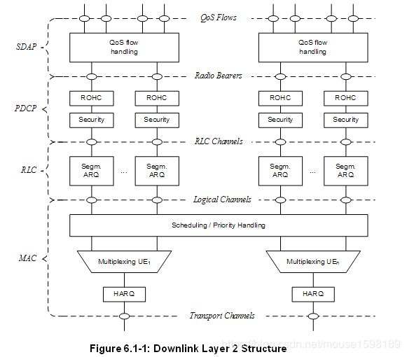

无线电承载分为两组:用于用户平面数据的数据无线电承载(DRB)和用于控制平面数据的信令无线电承载(SRB)。
6.2 MAC子层
6.2.1服务和功能
MAC子层的主要服务和功能包括:
- 逻辑信道和传输信道之间的映射;
- 属于一个或不同逻辑信道的MAC SDU在传输信道上传输到物理层/从传输信道上物理层传输的传输块(TB)的复用/解复用;
- 调度信息报告;
- 通过HARQ纠正错误(在CA的情况下每个载波一个HARQ实体);
- 通过动态调度在UE之间进行优先级处理;
- 通过逻辑信道优先级排序在一个UE的逻辑信道之间进行优先级处理;
- 填充。
单个MAC实体可以在逻辑信道优先级控制中支持一个或多个数字和/或传输定时和映射限制,逻辑信道可以使用哪个数字学和/或传输定时(参见子条款16.1.2)。
6.2.2逻辑信道
MAC提供的不同种类的数据传输服务。每种逻辑信道类型由传输的信息类型定义。逻辑信道分为两组:控制信道和业务信道。控制通道仅用于传输控制平面信息:
- 广播控制信道(BCCH):用于广播系统控制信息的下行链路信道。
- 寻呼控制信道(PCCH):传输寻呼信息和系统信息改变通知的下行链路信道。
- 公共控制信道(CCCH):用于在UE和网络之间发送控制信息的信道。该信道用于与网络没有RRC连接的UE。
- 专用控制信道(DCCH):在UE和网络之间发送专用控制信息的点对点双向信道。由具有RRC连接的UE使用。
流量通道仅用于传输用户平面信息: - 专用业务信道(DTCH):专用于一个UE的点对点信道,用于传输用户信息。 DTCH可以存在于上行链路和下行链路中。
6.2.3映射到传输信道
在Downlink中,存在逻辑信道和传输信道之间的以下连接:
- BCCH可以映射到BCH;
- BCCH可以映射到DL-SCH;
- PCCH可以映射到PCH;
- CCCH可以映射到DL-SCH;
- DCCH可以映射到DL-SCH;
- DTCH可以映射到DL-SCH。
在Uplink中,存在逻辑通道和传输通道之间的以下连接: - CCCH可以映射到UL-SCH;
- DCCH可以映射到UL-SCH;
- DTCH可以映射到UL-SCH。
6.2.4 HARQ
HARQ功能确保在第1层的对等实体之间的传递。当物理层未配置用于下行链路/上行链路空间复用时,单个HARQ进程支持一个TB,并且当物理层配置用于下行链路/上行链路空间复用时,单个HARQ进程支持一个或多个TB。
6.3 RLC子层
6.3.1传输模式
RLC子层支持三种传输模式:
- 透明模式(TM);
- 未确认模式(UM);
- 已确认模式(AM)。
RLC配置是每个逻辑信道,不依赖于数字和/或TTI持续时间,并且ARQ可以在逻辑信道配置的任何数字和/或TTI持续时间上操作。
对于SRB0,寻呼和广播系统信息,使用TM模式。对于其他SRB使用的AM模式。对于DRB,使用UM或AM模式。
6.3.2服务和功能
RLC子层的主要服务和功能取决于传输模式,包括:
- 传输上层PDU;
- 序列编号独立于PDCP(UM和AM)中的编号;
- 通过ARQ进行纠错(仅限AM);
- RLC SDU的分段(AM和UM)和重新分段(仅AM);
- 重组SDU(AM和UM);
- 重复检测(仅限AM);
- RLC SDU丢弃(AM和UM);
- RLC重建;
- 协议错误检测(仅限AM)。
6.3.3 ARQ
RLC子层内的ARQ具有以下特征:
- ARQ根据RLC状态报告重传RLC PDU或RLC PDU段;
- RLC需要时使用RLC状态报告轮询;
- RLC接收器还可以在检测到丢失的RLC PDU或RLC PDU段之后触发RLC状态报告。
6.4 PDCP子层
6.4.1服务和功能
用户平面的PDCP子层的主要服务和功能包括:
- 序列编号;
- 头部压缩和减压:仅限ROHC;
- 转移用户数据;
- 重新排序和重复检测;
- PDCP PDU路由(在分离承载的情况下);
- 重传PDCP SDU;
- 加密,解密和完整性保护;
- PDCP SDU丢弃;
- RLC AM的PDCP重建和数据恢复;
- 重复PDCP PDU。
用于控制平面的PDCP子层的主要服务和功能包括: - 序列编号;
- 加密,解密和完整性保护;
- 转移控制平面数据;
- 重新排序和重复检测;
- 重复PDCP PDU(见子条款16.1.3)。
6.5 SDAP子层
SDAP的主要服务和功能包括:
- QoS流和数据无线承载之间的映射;
- 在DL和UL分组中标记QoS流ID(QFI)。
为每个单独的PDU会话配置SDAP的单个协议实体。
6.6 L2数据流
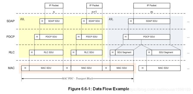
图6.6-1描述了第2层数据流的示例,其中通过连接来自RBx的两个RLC PDU和来自RBy的一个RLC PDU来由MAC生成传输块。 来自RBx的两个RLC PDU每个对应于一个IP分组(n和n + 1),而来自RBy的RLC PDU是IP分组(m)的分段。
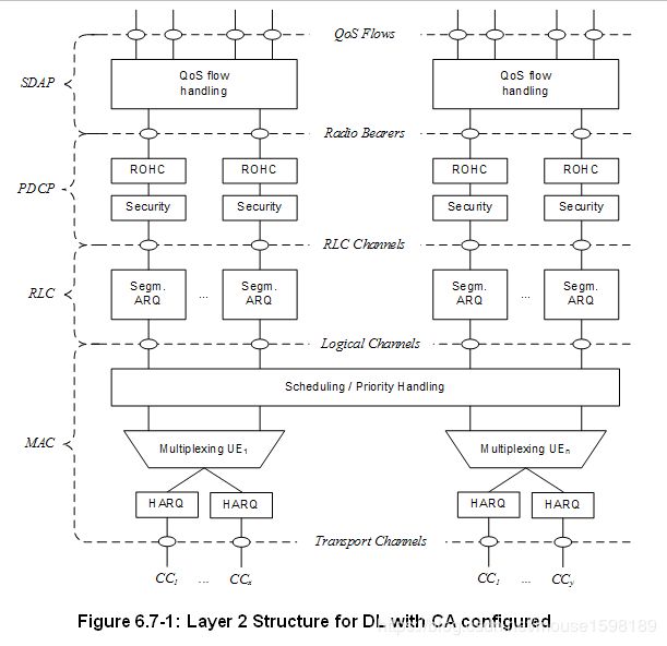
6.7载波聚合
在CA的情况下,物理层的多载波性质仅暴露于每个服务小区需要一个HARQ实体的MAC层,如下面的图6.7-1和6.7-2所示:
- 在上行链路和下行链路中,每个服务小区存在一个独立的混合ARQ实体,并且在没有空间复用的情况下,每个服务小区每个TTI生成一个传输块。 每个传输块及其潜在的HARQ重传被映射到单个服务小区。

6.8双连接
在DC的情况下,UE配置有两个MAC实体:用于MCG的一个MAC实体和用于SCG的一个MAC实体。 DC操作的更多细节可以在3GPP TS 37.340 [6]中找到。
6.9补充上行链路
在补充上行链路的情况下(SUL,参见3GPP TS 38.101 [18]),UE针对相同小区的一个DL配置有2个UL,并且这两个UL上的上行链路传输由网络控制以避免重叠的PUSCH传输。时间。此外,每个上行链路都支持初始访问(参见子条款9.2.6)。 SUL的一个例子见附件B.
6.10带宽适应
利用带宽自适应(BA),UE的接收和发送带宽不需要与小区的带宽一样大并且可以调整:可以命令宽度改变(例如,在低活动期间缩小以节省功率) );该位置可以在频域中移动(例如,以增加调度灵活性);并且可以命令子载波间隔改变(例如,以允许不同的服务)。小区的总小区带宽的子集被称为带宽部分(BWP),并且BA通过用BWP配置UE并且告知UE哪些配置的BWP当前是活动的来实现。
下面的图6.10-1描述了配置3个不同BWP的场景:
- BWP1,宽度为40 MHz,子载波间隔为15 kHz;
- BWP2,宽度为10 MHz,子载波间隔为15 kHz;
- BWP3,宽度为20 MHz,子载波间隔为60 kHz。

7 RRC
7.1服务和职能
RRC子层的主要服务和功能包括:
- 广播与AS和NAS相关的系统信息;
- 由5GC或NG-RAN发起的寻呼;
- 建立,维护和释放UE与NG-RAN之间的RRC连接,包括:
- 载波聚合的添加,修改和发布;
- 在NR中或在E-UTRA和NR之间添加,修改和释放双连接。
- 安全功能,包括密钥管理;
- 信令无线电承载(SRB)和数据无线电承载(DRB)的建立,配置,维护和发布;
- 移动功能包括:
- 移交和上下文转移;
- UE小区选择和重选以及小区选择和重选的控制;
- RAT间移动性。
- QoS管理功能;
- UE测量报告和报告控制;
- 检测无线电链路故障并从中恢复;
- 从/向UE向/从NAS传输NAS消息。
7.2协议状态
RRC支持以下状态,其特征如下:
- RRC_IDLE:
- PLMN选择;
- 广播系统信息;
- cell重选移动性;
- 移动终止数据的寻呼由5GC发起;
- 移动终接数据区域的寻呼由5GC管理;
- 由NAS配置的用于CN寻呼的DRX。
- RRC_INACTIVE: - 广播系统信息;
- cell重选移动性;
- 寻呼由NG-RAN(RAN寻呼)发起;
- 基于RAN的通知区域(RNA)由NG-RAN管理;
- 由NG-RAN配置的用于RAN寻呼的DRX;
- 为UE建立5GC-NG-RAN连接(两个C / U平面);
- UE AS上下文存储在NG-RAN和UE中;
- NG-RAN知道UE所属的RNA。
- RRC_CONNECTED: - 为UE建立5GC-NG-RAN连接(两个C / U平面);
- UE AS上下文存储在NG-RAN和UE中;
- NG-RAN知道UE所属的小区;
- 向/从UE传输单播数据;
- 网络控制的移动性包括测量。
7.3系统信息处理
系统信息(SI)分为最小SI和其他SI。最小SI是周期性广播的,并且包括初始接入所需的基本信息和用于定期或按需提供任何其他SI广播的信息,即调度信息。其他SI包含未在最小SI中广播的所有内容,并且可以由网络触发或者根据UE的请求以专用方式进行广播或提供,如下面的图7.3-1所示。
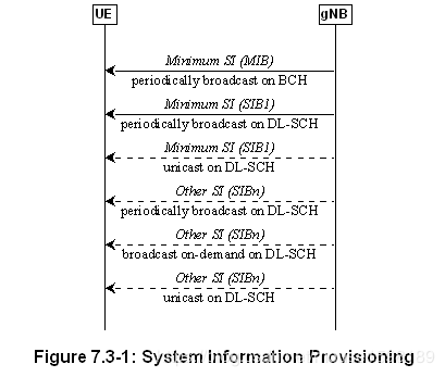
使用不同的消息(MasterInformationBlock和SystemInformationBlockType1)在两个不同的下行链路信道上发送最小SI。术语“剩余最小SI”(RMSI)也用于指代SystemInformationBlockType1。其他SI在SystemInformationBlockType2及更高版本中传输。
对于RRC_CONNECTED中的UE,专用RRC信令用于请求和传送其他SI。对于RRC_IDLE和RRC_INACTIVE中的UE,该请求触发随机接入过程(参见子条款9.2.6)并且通过MSG3承载,除非所请求的SI与PRACH资源的子集相关联,在这种情况下可以使用MSG1。当使用MSG1时,请求的最小粒度是一个SI消息(即一组SIB),一个RACH前导码可用于请求多个SI消息,并且gNB在MSG2中确认该请求。当使用MSG 3时,gNB在MSG4中确认该请求。
可以以可配置的周期性和特定持续时间广播其他SI。通过专用和UE特定的RRC信令来广播或传送其他SI是网络决策。
允许UE驻留的每个小区广播至少一些最小SI的内容,而系统中可能存在UE不能驻留的小区并且不广播最小SI。
对于UE考虑用于驻留的小区/频率,UE不需要从另一小区/频率层获取该小区/频率的最小SI的内容。这并不排除UE应用来自先前访问的小区的存储的SI的情况。
如果UE不能确定小区的最小SI的全部内容(通过从该小区接收或者从先前小区的有效存储的SI接收),则UE应该将该小区视为禁止的。
当多个数字在单个载波上混合时,只有默认值用于系统信息广播和寻呼。
7.4访问控制
NG-RAN支持过载和访问控制功能,例如RACH后退,RRC连接拒绝,RRC连接释放和基于UE的访问限制机制。
用于NR的一种统一接入限制机制解决了E-UTRA使用不同专用机制解决的所有用例和场景:每个接入尝试被分类为3GPP TS 22.261 [19]中规定的接入类别之一。
在RRC_IDLE中,UE NAS向RRC通知接入类别,并且连接请求包括一些信息以使gNB能够决定是否拒绝该请求。
7.5 UE能力检索框架
UE报告其至少在网络请求时是静态的UE无线电接入能力。 gNB可以基于频带信息请求UE报告哪些能力。
当网络允许时,UE可以发送临时能力限制请求以向gNB发信号通知某些能力(例如,由于硬件共享,干扰或过热)的有限可用性。然后,gNB可以确认或拒绝该请求。临时能力限制应对5GC透明。即,只有静态功能存储在5GC中。
7.6 NAS消息的传输
NR在RRC中的SRB上提供可靠的按顺序递送NAS消息,除了在重新建立PDCP时可能发生丢失或重复的切换。 在RRC中,NAS消息以透明容器发送。 在以下场景中可能会发生NAS消息的捎带:
- 在DL中的承载建立/修改/释放;
- 用于在UL中连接建立和连接恢复期间传输初始NAS消息。
注意:除了NAS执行的完整性保护和加密之外,NAS消息还可以通过PDCP进行完整性保护和加密。
7.7 载波聚合
当配置CA时,UE仅与网络具有一个RRC连接。在RRC连接建立/重建/切换时,一个服务小区提供NAS移动性信息,并且在RRC连接重建/切换时,一个服务小区提供安全性输入。该小区称为主小区(PCell)。取决于UE能力,辅小区(SCell)可以被配置为与PCell一起形成一组服务小区。因此,用于UE的配置的服务小区集合总是由一个PCell和一个或多个SCell组成。
可以由RRC执行SCell的重新配置,添加和移除。在NR内切换时,RRC还可以添加,移除或重新配置SCell以供与目标PCell一起使用。当添加新SCell时,专用RRC信令用于发送SCell的所有所需系统信息,即,当处于连接模式时,UE不需要直接从SCell获取广播系统信息。
7.8带宽适应
为了在PCell上启用BA,gNB使用UL和DL BWP对配置UE。为了在CA的情况下在SCell上启用BA,gNB至少为UE配置DL BWP(即,UL中可能没有)。
8 NG 标识
8.1 UE标识
对于连接到5GC的NR,在小区级别使用以下UE标识:
- C-RNTI:唯一标识,用作RRC连接的标识符和用于调度;
- 临时C-RNTI:用于随机接入过程的标识;
- 争用解决的随机值:在一些瞬态状态期间,UE被临时识别为用于争用解决目的的随机值。
对于连接到5GC的NR,在NG-RAN级别使用以下UE标识: - I-RNTI:用于标识RRC_INACTIVE的UE上下文的唯一标识。
8.2网络身份
NG-RAN中使用以下标识来标识特定网络实体: - AMF标识符:用于识别AMF。
- NR小区全球标识符(NCGI):用于全球识别NR小区。 NCGI由小区所属的PLMN标识和小区的NR小区标识(NCI)构成。
- gNB标识符(gNB ID):用于标识PLMN内的gNB。 gNB ID包含在其小区的NCI内。
- 全球gNB ID:用于全局识别gNB。全局gNB ID由gNB所属的PLMN标识和gNB ID构成。 MCC和MNC与NCGI中包含的相同。
- 跟踪区域标识(TAI):用于标识跟踪区域。 TAI由跟踪区域所属的PLMN标识和跟踪区域的TAC(跟踪区域代码)构成。
- 单网络切片选择辅助信息(S-NSSAI):标识网络切片。
9移动性和状态转变
9.1概述
在NR中通过切换,在RRC释放时的重定向机制以及通过使用频率间和RAT间绝对优先级和频率间Qoffset参数来实现负载平衡。
UE针对连接模式移动性执行的测量被分类为至少三种测量类型:
- 频率内测量;
- 频率间测量;
- RAT间测量。
对于每种测量类型,可以定义一个或多个测量对象(测量对象定义例如要监视的载波频率)。
对于每个测量对象,可以定义一个或多个报告配置(报告配置定义报告标准)。使用了三个报告标准:事件触发报告,定期报告和事件触发定期报告。
测量对象和报告配置之间的关联由测量标识创建(测量标识将一个测量对象和同一RAT的一个报告配置链接在一起)。通过使用多个测量标识(每个测量对象一个,报告配置对),可以: - 将多个报告配置与一个测量对象相关联;
- 将一个报告配置与多个测量对象相关联。
在报告测量结果时也使用测量标识。
每个RAT单独考虑测量数量。
NG-RAN使用测量命令来命令UE启动,修改或停止测量。
9.2内部-NR
9.2.1 RRC_IDLE中的移动性
9.2.1.1小区选择
NR中的PLMN选择的原理基于3GPP PLMN选择原则。从RM-REGISTERED到RM-REGISTERED,从CM-IDLE到CM-CONNECTED以及从CM-CONNECTED到CM-IDLE的转换需要小区选择,并且基于以下原则:
- UE NAS层识别所选择的PLMN和等效PLMN;
- UE搜索NR个频带,并且对于每个载波频率识别最强的小区。它读取广播的小区系统信息以识别其PLMN:
- UE可以依次搜索每个载波(“初始小区选择”)或利用存储的信息来缩短搜索(“存储的信息小区选择”)。
- UE寻求识别合适的小区;如果它无法识别合适的细胞,则寻求识别可接受的细胞。当找到合适的细胞或者如果仅发现可接受的细胞时,它会在该细胞上驻留并开始细胞重选过程:
- 合适的小区是测量的小区属性满足小区选择标准的小区;小区PLMN是选择的PLMN,注册的或等效的PLMN;该小区不被禁止或保留,并且该小区不是跟踪区域的一部分,该跟踪区域位于“禁止漫游的跟踪区域”列表中;
- 可接受的细胞是测量的细胞属性满足细胞选择标准并且细胞未被禁止的细胞。
过渡到RRC_IDLE:
在从RRC_CONNECTED转换到RRC_IDLE时,UE应驻留在其处于RRC_CONNECTED的最后一个小区或者在状态转换消息中由RRC分配小区/小区集合或频率的任何小区。
从覆盖范围内恢复:
UE应该尝试以上面针对存储信息或初始小区选择所描述的方式找到合适的小区。如果在任何频率或RAT上没有找到合适的小区,则UE应该尝试找到可接受的小区。
在多波束操作中,在对应于相同小区的波束中导出小区质量(参见子条款9.2.4)。
9.2.1.2小区重选
处于RRC_IDLE的UE执行小区重选。该程序的原则如下: - UE测量服务小区和相邻小区的属性以启用重选过程:
- 对于频率间相邻小区的搜索和测量,仅需要指示载波频率。
- 小区重选标识UE应驻留的小区。它基于小区重选标准,涉及服务和相邻小区的测量:
- 频率内重选基于小区的排名;
- 频率间重选基于绝对优先级,其中UE试图驻留在可用的最高优先级频率上;
- 服务小区可以提供NCL来处理频率内和频率间相邻小区的特定情况;
- 可以提供黑名单以防止UE重选到特定的频率内和频率间相邻小区;
- 小区重选可以取决于速度;
- 服务特定优先级。
在多波束操作中,在对应于相同小区的波束中导出小区质量(参见子条款9.2.4)。
9.2.2 RRC_INACTIVE中的移动性
9.2.2.1概述
RRC_INACTIVE是UE保持在CM-CONNECTED并且可以在由NG-RAN(RNA)配置的区域内移动而不通知NG-RAN的状态。在RRC_INACTIVE中,最后服务gNB节点将UE上下文和UE相关NG连接与服务AMF和UPF保持在一起。
如果最后服务gNB在UE处于RRC_INACTIVE时从UPF接收DL数据或者从AMF接收DL信令,则其在与RNA对应的小区中寻呼,并且如果RNA包括小区,则可以将XnAP RAN寻呼发送到邻居gNB(s)邻居gNB的。
在RAN寻呼失败时,gNB根据3GPP TS 23.501 [3]行事。
AMF向NG-RAN节点提供RRC非活动助理信息以帮助NG-RAN节点决定是否可以将UE发送到RRC_INACTIVE。 RRC非活动助理信息包括为UE配置的注册区域,UE特定DRX,周期性注册更新定时器,AMF是否配置有移动发起连接(MICO)模式的指示,以及UE身份索引值。当配置基于RAN的通知区域时,NG-RAN节点考虑UE注册区域。 NG特定DRX和UE标识索引值由NG-RAN节点用于RAN寻呼。 NG-RAN节点考虑周期性注册更新定时器以配置周期性RAN通知区域更新定时器。
在转换到RRC_INACTIVE时,NG-RAN节点可以为UE配置周期性RNA更新定时器值。在没有来自UE的通知的周期性RNA更新定时器到期时,gNB的行为与3GPP TS 23.501 [3]中规定的相同。
如果UE接入除最后服务gNB之外的gNB,则接收gNB触发XnAP检索UE上下文过程以从最后服务gNB获得UE上下文,并且还可以触发包括用于从中潜在恢复数据的隧道信息的数据转发过程。最后一个服务gNB。在成功上下文检索后,接收gNB成为服务gNB,并且它还触发NGAP路径切换请求过程。在路径切换过程之后,服务gNB通过XnAP UE上下文释放过程触发在最后服务gNB处释放UE上下文。
如果UE接入除了最后服务gNB之外的gNB并且接收gNB没有找到有效的UE上下文,则gNB执行新的RRC连接的建立而不是恢复先前的RRC连接。
处于RRC_INACTIVE状态的UE在移出配置的RNA时需要启动RNA更新过程。当从UE接收RNA更新请求时,接收gNB可以决定将UE发送回RRC_INACTIVE状态,将UE移动到RRC_CONNECTED状态,或者将UE发送到RRC_IDLE。
9.2.2.2小区重选
空。
RRC_INACTIVE中的小区重选未完成,目标是在2018年6月完成。
9.2.2.3基于RAN的通知区域
处于RRC_INACTIVE状态的UE可以配置有RNA,其中: - RNA可以覆盖单个或多个细胞,并且可以小于CN区域;
- UE周期性地发送基于RAN的通知区域更新(RNAU),并且当UE的小区重选过程选择不属于所配置的RNA的小区时,还发送基于RAN的通知区域更新(RNAU)。
有关如何配置RNA的方法有以下几种: - 单元格列表:
- 向UE提供构成RNA的明确的细胞列表(一个或多个)。
- RAN区域列表:
- 提供UE(至少一个)RAN区域ID,其中RAN区域是CN跟踪区域的子集;
- 小区在系统信息中广播(至少一个)RAN区域ID,使得UE知道该小区属于哪个区域。
9.2.2.4国家过渡
9.2.2.4.1 UE触发从RRC_INACTIVE到RRC_CONNECTED的转换
下图描述了UE触发从RRC_INACTIVE到RRC_CONNECTED的转换:

- The UE resumes from RRC_INACTIVE, providing the I-RNTI, allocated by the last serving gNB.
- The gNB, if able to resolve the gNB identity contained in the I-RNTI, requests the last serving gNB to provide UE Context data.
- The last serving gNB provides UE context data.
- The gNB completes the resumption of the RRC connection.
- If loss of DL user data buffered in the last serving gNB shall be prevented, the gNB provides forwarding addresses.
6./7. The gNB performs path switch. - The gNB triggers the release of the UE resources at the last serving gNB.
After step 1 above, when the gNB decides to reject the Resume Request and keep the UE in RRC_INACTIVE without any reconfiguration, or when the gNB decides to setup a new RRC connection, SRB0 (without security) can be used. When the gNB decides to reconfigure the UE (e.g. with a new DRX cycle or RNA) or when the gNB decides to push the UE to RRC_IDLE, SRB1 (with at least integrity protection) shall be used.
NOTE: SRB1 can only be used once the UE Context is retrieved i.e. after step 3.
9.2.2.4.2 Network triggered transition from RRC_INACTIVE to RRC_CONNECTED
The following figure describes the network triggered transition from RRC_INACTIVE to RRC_CONNECTED:
Figure 9.2.2.4.2-1: Network triggered transition from RRC_INACTIVE to RRC_CONNECTED
- A RAN paging trigger event occurs (incoming DL user plane, DL signalling from 5GC, etc.).
- RAN paging is triggered; either only in the cells controlled by the last serving gNB or also by means of Xn RAN Paging, in other gNBs, being member of the RAN Paging area the UE is registered with.
- The UE is paged with an NG-RAN allocated UE identity.
- If the UE has been successfully reached, it attempts to resume from RRC_INACTIVE, as described in other sections.
9.2.2.5 RNA update
The following figure describes the UE triggered RNA update procedure when it moves out of the configured RNA involving context retrieval over Xn:
Figure 9.2.2.5-1: RNA update procedure
- The UE resumes from RRC_INACTIVE, providing the I-RNTI allocated by the last serving gNB and appropriate cause value, e.g., RAN notification area update.
- The gNB, if able to resolve the gNB identity contained in the I-RNTI, requests the last serving gNB to provide UE Context.
- The last serving gNB provides UE context.
- The gNB may move the UE to RRC_CONNECTED, or send the UE back to RRC_INACTIVE state or send the UE to RRC_IDLE. If the UE is sent to RRC_IDLE, the following steps are not needed.
- If loss of DL user data buffered in the last serving gNB shall be prevented, the gNB provides forwarding addresses.
6./7. The gNB performs path switch. - The gNB triggers the release of the UE resources at the last serving gNB.
9.2.3 Mobility in RRC_CONNECTED
9.2.3.1 Overview
Network controlled mobility applies to UEs in RRC_CONNECTED and is categorized into two types of mobility: cell level mobility and beam level mobility.
Cell Level Mobility requires explicit RRC signalling to be triggered, i.e. handover. For inter-gNB handover, the signalling procedures consist of at least the following elemental components illustrated in Figure 9.2.3.1-1:
Figure 9.2.3.1-1: Inter-gNB handover procedures
- The source gNB initiates handover and issues a Handover Request over the Xn interface.
- The target gNB performs admission control and provides the RRC configuration as part of the Handover Acknowledgement.
- The source gNB provides the RRC configuration to the UE in the Handover Command. The Handover Command message includes at least cell ID and all information required to access the target cell so that the UE can access the target cell without reading system information. For some cases, the information required for contention based and contention free random access can be included in the Handover Command message. The access information to the target cell may include beam specific information, if any.
- The UE moves the RRC connection to the target gNB and replies the Handover Complete.
The handover mechanism triggered by RRC requires the UE at least to reset the MAC entity and re-establish RLC. RRC managed handovers with and without PDCP entity re-establishment are both supported. For DRBs using RLC AM mode, PDCP can either be re-established together with a security key change or initiate a data recovery procedure without a key change. For DRBs using RLC UM mode and for SRBs, PDCP can either be re-established together with a security key change or remain as it is without a key change.
Data forwarding, in-sequence delivery and duplication avoidance at handover can be guaranteed when the target gNB uses the same DRB configuration and QoS flow to DRB mapping as the source gNB.
Timer based handover failure procedure is supported in NR. RRC connection re-establishment procedure is used for recovering from handover failure.
Beam Level Mobility does not require explicit RRC signalling to be triggered - it is dealt with at lower layers - and RRC is not required to know which beam is being used at a given point in time.
9.2.3.2 Handover
9.2.3.2.1 C-Plane Handling
The intra-NR RAN handover performs the preparation and execution phase of the handover procedure performed without involvement of the 5GC, i.e. preparation messages are directly exchanged between the gNBs. The release of the resources at the source gNB during the handover completion phase is triggered by the target gNB. The figure below depicts the basic handover scenario where neither the AMF nor the UPF changes:
Figure 9.2.3.2.1-1: Intra-AMF/UPF Handover
0. The UE context within the source gNB contains information regarding roaming and access restrictions which were provided either at connection establishment or at the last TA update.
- The source gNB configures the UE measurement procedures and the UE reports according to the measurement configuration.
- The source gNB decides to handover the UE, based on MEASUREMENT REPORT and RRM information.
- The source gNB issues a HANDOVER REQUEST message to the target gNB passing a transparent RRC container with necessary information to prepare the handover at the target side. The information includes at least the target cell ID, KgNB*, the C-RNTI of the UE in the source gNB, RRM-configuration including UE inactive time, basic AS-configuration including antenna Info and DL Carrier Frequency, the UE capabilities for different RATs, and can include the UE reported measurement information including beam-related information if available. Also, if CA is configured, the RRM configuration can include the list of best cells on each frequency for which measurement information is available.
- Admission Control may be performed by the target gNB.
- The target gNB prepares the handover with L1/L2 and sends the HANDOVER REQUEST ACKNOWLEDGE to the source gNB. The HANDOVER REQUEST ACKNOWLEDGE message includes a transparent container to be sent to the UE as an RRC message to perform the handover.
- The source gNB triggers the Uu handover and sends the Handover Command message to the UE. The Handover Command message carries the information required to access the target cell, which includes at least the target cell ID, the new C-RNTI, the target gNB security algorithm identifiers for the selected security algorithms, can include a set of dedicated RACH resources, the association between RACH resources and SS blocks, the association between RACH resources and UE-specific CSI-RS configuration(s), common RACH resources, and target gNB SIBs, etc.
- The source gNB sends the SN STATUS TRANSFER message to the target gNB.
- The UE synchronises to the target cell and completes the RRC handover procedure.
- The target gNB sends a PATH SWITCH REQUEST message to AMF to trigger 5GC to switch the DL data path towards the target gNB and to establish an NG-C interface instance towards the target gNB.
- 5GC switches the DL data path towards the target gNB.
- The AMF confirms the PATH SWITCH REQUEST message with the PATH SWITCH REQUEST ACKNOWLEDGE message.
- By sending the UE CONTEXT RELEASE message, the target gNB informs the source gNB about the success of handover and triggers the release of resources by the source gNB. The target gNB sends this message after the PATH SWITCH REQUEST ACKNOWLEDGE message is received from the AMF. Upon reception of the UE CONTEXT RELEASE message, the source gNB can release radio and C-plane related resources associated to the UE context. Any ongoing data forwarding may continue.
The RRM configuration can include both beam measurement information (for layer 3 mobility) associated to SS Block(s) and CSI-RS(s) for the reported cell (or cells FFS) if both types of measurements are available.
The common RACH configuration for beams in the target cell is only associated to the SS Block(s). The network can have dedicated RACH configurations associated to the SS Block(s) and/or have dedicated RACH configurations associated to CSI-RS(s) within a cell. The target gNB can only include one of the following RACH configurations in the Handover Command to enable the UE to access the target cell:
i) Common RACH configuration;
ii) Common RACH configuration + Dedicated RACH configuration associated with SS-Block;
iii) Common RACH configuration + Dedicated RACH configuration associated with CSI-RS.
The dedicated RACH configuration allocates RACH resource(s) together with a quality threshold to use them. When dedicated RACH resources are provided, they are prioritized by the UE and the UE shall not switch to contention-based RACH resources as long as the quality threshold of those dedicated resources is met. The order to access the dedicated RACH resources is up to UE implementation.
9.2.3.2.2 U-Plane Handling
Void.
U-Plane handling for handover is not complete and is targeted for completion in June 2018.
9.2.4 Measurements
In RRC_CONNECTED, the UE measures multiple beams (at least one) of a cell and the measurements results (power values) are averaged to derive the cell quality. In doing so, the UE is configured to consider a subset of the detected beams: the N best beams above an absolute threshold. Filtering takes place at two different levels: at the physical layer to derive beam quality and then at RRC level to derive cell quality from multiple beams. Cell quality from beam measurements is derived in the same way for the serving cell(s) and for the non-serving cell(s). Measurement reports may contain the measurement results of the X best beams if the UE is configured to do so by the gNB.
The corresponding high-level measurement model is described below:
Figure 9.2.4-1: Measurement Model
NOTE: K beams correspond to the measurements on NR-SS block or CSI-RS resources configured for L3 mobility by gNB and detected by UE at L1.
- A: measurements (beam specific samples) internal to the physical layer.
- Layer 1 filtering: internal layer 1 filtering of the inputs measured at point A. Exact filtering is implementation dependent. How the measurements are actually executed in the physical layer by an implementation (inputs A and Layer 1 filtering) in not constrained by the standard.
- A1: measurements (i.e. beam specific measurements) reported by layer 1 to layer 3 after layer 1 filtering.
- Beam Consolidation/Selection: beam specific measurements are consolidated to derive cell quality if N > 1, else when N = 1 the best beam measurement is selected to derive cell quality. The behaviour of the Beam consolidation/selection is standardised and the configuration of this module is provided by RRC signalling. Reporting period at B equals one measurement period at A1.
- B: a measurement (i.e. cell quality) derived from beam-specific measurements reported to layer 3 after beam consolidation/selection.
- Layer 3 filtering for cell quality: filtering performed on the measurements provided at point B. The behaviour of the Layer 3 filters is standardised and the configuration of the layer 3 filters is provided by RRC signalling. Filtering reporting period at C equals one measurement period at B.
- C: a measurement after processing in the layer 3 filter. The reporting rate is identical to the reporting rate at point B. This measurement is used as input for one or more evaluation of reporting criteria.
- Evaluation of reporting criteria: checks whether actual measurement reporting is necessary at point D. The evaluation can be based on more than one flow of measurements at reference point C e.g. to compare between different measurements. This is illustrated by input C and C1. The UE shall evaluate the reporting criteria at least every time a new measurement result is reported at point C, C1. The reporting criteria are standardised and the configuration is provided by RRC signalling (UE measurements).
- D: measurement report information (message) sent on the radio interface.
- L3 Beam filtering: filtering performed on the measurements (i.e. beam specific measurements) provided at point A1. The behaviour of the beam filters is standardised and the configuration of the beam filters is provided by RRC signalling. Filtering reporting period at E equals one measurement period at A1.
- E: a measurement (i.e. beam-specific measurement) after processing in the beam filter. The reporting rate is identical to the reporting rate at point A1. This measurement is used as input for selecting the X measurements to be reported.
- Beam Selection for beam reporting: selects the X measurements from the measurements provided at point E. The behaviour of the beam selection is standardised and the configuration of this module is provided by RRC signalling.
- F: beam measurement information included in measurement report (sent) on the radio interface.
Layer 1 filtering introduces a certain level of measurement averaging. How and when the UE exactly performs the required measurements is implementation specific to the point that the output at B fulfils the performance requirements set in 3GPP TS 38.133 [13]. Layer 3 filtering for cell quality and related parameters used are specified in 3GPP TS 38.331 [12] and does not introduce any delay in the sample availability between B and C. Measurement at point C, C1 is the input used in the event evaluation. L3 Beam filtering and related parameters used are specified in 3GPP TS 38.331 [12] and do not introduce any delay in the sample availability between E and F.
Measurement reports are characterized by the following: - Measurement reports include the measurement identity of the associated measurement configuration that triggered the reporting;
- Cell and beam measurement quantities to be included in measurement reports are configured by the network;
- The number of non-serving cells to be reported can be limited through configuration by the network;
- Cells belonging to a blacklist configured by the network are not used in event evaluation and reporting, and conversely when a whitelist is configured by the network, only the cells belonging to the whitelist are used in event evaluation and reporting;
- Beam measurements to be included in measurement reports are configured by the network (beam identifier only, measurement result and beam identifier, or no beam reporting).
9.2.5 Paging
The UE in RRC_IDLE and RRC_INACTIVE states may use DRX in order to reduce power consumption. While in RRC_IDLE the UE monitors 5GC-initiated paging, in RRC_INACTIVE the UE is reachable via RAN-initiated paging and 5GC-initiated paging. RAN and 5GC paging occasions overlap and same paging mechanism is used. The UE monitors one paging occasion per DRX cycle for the reception of paging as follows: - Paging DRX cycle length is configurable:
- A default DRX cycle for CN paging is configurable via system information;
- A UE specific DRX cycle for CN paging is configurable via UE dedicated signalling.
- NG-RAN can configure a UE with a DRX cycle for RAN paging. This configuration can be UE specific.
- The number of paging occasions in a DRX cycle is configurable via system information:
- A network may distribute UEs to the paging occasions based on UE id when multiple paging occasions are configured in the DRX cycle.
- Paging occasion can consist of multiple time slots (e.g. subframe or OFDM symbol). The number of time slots in a paging occasion is configurable via system information:
- A network may transmit a paging using a different set of DL Tx beam(s) or repetitions in each time slot.
9.2.6 Random Access Procedure
The random access procedure is triggered by a number of events, for instance: - Initial access from RRC_IDLE;
- RRC Connection Re-establishment procedure;
- Handover;
- DL or UL data arrival during RRC_CONNECTED when UL synchronisation status is “non-synchronised”;
- Transition from RRC_INACTIVE;
- Request for Other SI (see subclause 7.3).
Furthermore, the random access procedure takes two distinct forms: contention based and non-contention based as shown on Figure 9.2.6-1 below. Normal DL/UL transmission can take place after the random access procedure.
For initial access in a cell configured with SUL, the UE selects the SUL carrier if and only if the measured quality of the DL is lower than a broadcast threshold. Once started, all uplink transmissions of the random access procedure remain on the selected carrier.
(a) Contention Based (b) Contention Free
Figure 9.2.6-1: Random Access Procedures
9.2.7 Radio Link Failure
In RRC_CONNECTED, the UE declares Radio Link Failure (RLF) when one of the following criteria are met:
- Expiry of a timer started after indication of radio problems from the physical layer (if radio problems are recovered before the timer is expired, the UE stops the timer);
- Random access procedure failure;
- RLC failure.
After RLF is declared, the UE: - stays in RRC_CONNECTED;
- selects a suitable cell and then initiates RRC re-establishment;
- enters RRC_IDLE if a suitable cell wasn’t found within a certain time after RLF was declared.
9.3 Inter RAT
9.3.1 Intra 5GC
9.3.1.1 Cell Reselection
Cell reselection is characterised by the following: - Cell reselection between NR RRC_IDLE and E-UTRA RRC_IDLE is supported;
9.3.1.2 Handover
Inter RAT mobility is characterised by the following: - Source RAT should be able to support and configure Target RAT measurement and reporting.
- The in-sequence and lossless handover is supported for the handover between gNB and ng-eNB.
- Both Xn and NG based inter-RAT handover between NG-RAN nodes is supported. Whether the handover is over Xn or CN is transparent to the UE.
- The target RAT receives the UE NG-C context information and based on this information configures the UE with a complete RRC message and Full configuration (not delta).
9.3.1.3 Measurements
Inter RAT measurements in NR are limited to E-UTRA.
9.3.2 From 5GC to EPC
9.3.2.1 Cell Reselection
Cell reselection is characterised by the following: - Cell reselection between NR RRC_IDLE and E-UTRA RRC_IDLE is supported.
9.3.2.2 Handover
Inter RAT mobility is characterised by the following: - Source RAT should be able to support and configure Target RAT measurement and reporting.
9.3.2.3 Measurements
Inter RAT measurements in NR are limited to E-UTRA.
9.3.2.4 Data Forwarding
The inter-System data forwarding follows the following key principles: - Only indirect data forwarding is supported.
- PDU session information at the serving NG-RAN node contains mapping information per QoS Flow to a corresponding E-RAB.
- At handover preparation, the source NG-RAN node shall decide which mapped E-RABs are proposed to be subject to data forwarding and provide this information in the source-to-target container to the target eNB.
- The target eNB assigns forwarding TEID/TNL address(es) for the E-RAB(s) for which it accepts data forwarding.
- A single data forwarding tunnel is established between the source NG-RAN node and UPF per PDU session for which at least data for a single QoS Flow is subject to data forwarding. Then the UPF maps data received from the per PDU session data forwarding tunnel(s) to the mapped EPS bearer(s).
9.4 Roaming and Access Restrictions
The roaming and access restriction information for a UE includes information on restrictions to be applied for subsequent mobility action during CM-CONNECTED state. It may be provided by the AMF and also may be updated by the AMF later.
It includes the forbidden RAT, the forbidden area and the service area restrictions as specified in 3GPP TS 23.501 [3]. It also includes serving PLMN and may include a list of equivalent PLMNs.
Upon receiving the roaming and access restriction information for a UE, if applicable, the gNB should use it to determine whether to apply restriction handling for subsequent mobility action, e.g., handover, redirection.
If the roaming and access restriction information is not available for a UE at the gNB, the gNB shall consider that there is no restriction for subsequent mobility actions.
Only if received over NG or Xn signalling, the roaming and access restriction information shall be propagated over Xn by the source gNB during Xn handover. If the Xn handover results in a change of serving PLMN (to an equivalent PLMN), the source gNB shall replace the serving PLMN with the identity of the target PLMN and move the serving PLMN to the equivalent PLMN list, before propagating the roaming and access restriction information.
10 Scheduling
10.1 Basic Scheduler Operation
In order to utilise radio resources efficiently, MAC in gNB includes dynamic resource schedulers that allocate physical layer resources for the downlink and the uplink. In this subclause, an overview of the scheduler is given in terms of scheduler operation, signalling of scheduler decisions, and measurements.
Scheduler Operation:
- Taking into account the UE buffer status and the QoS requirements of each UE and associated radio bearers, schedulers assign resources between UEs;
- Schedulers may assign resources taking account the radio conditions at the UE identified through measurements made at the gNB and/or reported by the UE;
- Schedulers assign radio resources in a unit of TTI (e.g. one mini-slot, one slot, or multiple slots);
- Resource assignment consists of radio resources (resource blocks).
Signalling of Scheduler Decisions: - UEs identify the resources by receiving a scheduling (resource assignment) channel.
Measurements to Support Scheduler Operation: - Uplink buffer status reports (measuring the data that is buffered in the logical channel queues in the UE) are used to provide support for QoS-aware packet scheduling.
- The buffer reporting scheme used in uplink is flexible to support different types of data services. Constraints on how often uplink buffer reports are signalled from the limits the overhead from sending the reports in the uplink.
10.2 Downlink Scheduling
In the downlink, the gNB can dynamically allocate resources to UEs via the C-RNTI on PDCCH(s). A UE always monitors the PDCCH(s) in order to find possible allocation when its downlink reception is enabled (activity governed by DRX when configured). When CA is configured, the same C-RNTI applies to all serving cells.
In addition, the gNB can allocate Configured Scheduling (CS) resources for the initial HARQ transmissions to UEs: RRC defines the periodicity of the CS grant and PDCCH addressed to CS-RNTI activates the CS resources i.e. it indicates that the downlink grant is a CS one and that it can be implicitly reused according to the periodicity defined by RRC, until deactivated.
NOTE: when required, retransmissions are explicitly scheduled on PDCCH(s).
When the UE has downlink CS resources configured, if the UE cannot find its C-RNTI on the PDCCH(s), a downlink transmission according to the CS configuration is assumed. Otherwise, if the UE finds its C-RNTI on the PDCCH(s), the PDCCH allocation overrides the CS one and the UE does not decode the CS resources.
When CA is configured, at most one CS configuration can be signalled per serving cell. When BA is configured, at most one CS configuration can be signalled per BWP. On each serving cell, there can be only one CS configuration active at a time.
10.3 Uplink Scheduling
In the uplink, the gNB can dynamically allocate resources to UEs via the C-RNTI on PDCCH(s). A UE always monitors the PDCCH(s) in order to find possible allocation for uplink transmission when its downlink reception is enabled (activity governed by DRX when configured). When CA is configured, the same C-RNTI applies to all serving cells.
In addition, the gNB can allocate CS resources for the initial HARQ transmissions: - Type 1: with uplink Type 1 CS resources, RRC defines the grant and no PDCCH is needed.
- Type 2: with uplink Type 2 CS resources, RRC defines the periodicity of the CS grant and PDCCH addressed to CS-RNTI activates the CS resources i.e. it indicates that the downlink grant is a CS one and that it can be implicitly reused according to the periodicity defined by RRC, until deactivated.
When the UE has uplink CS resources configured, if the UE cannot find its C-RNTI on the PDCCH(s), an uplink transmission according to the CS configuration can be made. Otherwise, if the UE finds its C-RNTI on the PDCCH(s), the PDCCH allocation overrides the CS one and the UE’s transmission follows the PDCCH allocation, not CS one.
Retransmissions other than repetitions are explicitly allocated via PDCCH(s).
When CA is configured, at most one CS configuration can be signalled per serving cell. When BA is configured, at most one CS configuration can be signalled per BWP. On each serving cell, there can be only one CS configuration active at a time.
10.4 Measurements to Support Scheduler Operation
Measurement reports are required to enable the scheduler to operate in both uplink and downlink. These include transport volume and measurements of a UEs radio environment.
Uplink buffer status reports (BSR) are needed to provide support for QoS-aware packet scheduling. In NR, uplink buffer status reports refer to the data that is buffered in for a group of logical channel (LCG) in the UE. Eight LCGs and two formats are used for reporting in uplink: - A short format to report only one BSR (of one LCG);
- A flexible long format to report several BSRs (up to all eight LCGs).
Uplink buffer status reports are transmitted using MAC signalling.
10.5 Rate Control
10.5.1 Downlink
Void.
Downlink rate control is not complete and is targeted for completion in June 2018.
10.5.2 Uplink
The UE has an uplink rate control function which manages the sharing of uplink resources between logical channels. RRC controls the uplink rate control function by giving each logical channel a priority, a prioritised bit rate (PBR), and a buffer size duration (BSD). The values signalled need not be related to the ones signalled via NG to the gNB. In addition, mapping restrictions can be configured (see subclause 6.2.1).
The uplink rate control function ensures that the UE serves the logical channel(s) in the following sequence:
- All relevant logical channels in decreasing priority order up to their PBR;
- All relevant logical channels in decreasing priority order for the remaining resources assigned by the grant.
NOTE 1: In case the PBRs are all set to zero, the first step is skipped and the logical channels are served in strict priority order: the UE maximises the transmission of higher priority data.
NOTE 2: The mapping restrictions tell the UE which logical channels are relevant for the grant received. If no mapping restrictions are configured, all logical channels are considered.
If more than one radio bearers have the same priority, the UE shall serve these radio bearers equally.
10.6 Activation/Deactivation Mechanism
To enable reasonable UE battery consumption when CA is configured, an activation/deactivation mechanism of Cells is supported. When a Cell is deactivated, the UE does not need to receive the corresponding PDCCH or PDSCH, cannot transmit in the corresponding uplink, nor is it required to perform CQI measurements. Conversely, when a Cell is active, the UE shall receive PDSCH and PDCCH (if the UE is configured to monitor PDCCH from this SCell), and is expected to be able to perform CQI measurements.
At reconfiguration without mobility control information:
- SCells added to the set of serving cells are initially deactivated;
- SCells which remain in the set of serving cells (either unchanged or reconfigured) do not change their activation status (activated or deactivated).
At reconfiguration with mobility control information (i.e. handover): - SCells are deactivated.
To enable reasonable UE battery consumption when BA is configured, only one BWP pair can be active at a time, all others BWPs that the UE is configured with being deactivated. On deactivated BWPs, the UE does not monitor the PDCCH, does not transmit on PUCCH, PRACH and UL-SCH.
11 UE Power Saving
The PDCCH monitoring activity of the UE is governed by DRX and BA.
When DRX is configured, the UE does not have to continuously monitor PDCCH. DRX is characterized by the following:
- on-duration: duration that the UE waits for, after waking up, to receive PDCCHs. If the UE successfully decodes a PDCCH, the UE stays awake and starts the inactivity timer;
- inactivity-timer: duration that the UE waits to successfully decode a PDCCH, from the last successful decoding of a PDCCH, failing which it can go back to sleep. The UE shall restart the inactivity timer following a single successful decoding of a PDCCH for a first transmission only (i.e. not for retransmissions);
- retransmission-timer: duration until a retransmission can be expected;
- cycle: specifies the periodic repetition of the on-duration followed by a possible period of inactivity (see figure 11-1 below).
Figure 11-1: DRX Cycle
When BA is configured, the UE only has to monitor PDCCH on the one active BWP i.e. it does not have to monitor PDCCH on the entire DL frequency of the cell. A BWP inactivity timer (independent from the DRX inactivity-timer described above) is used to switch the active BWP to the default one: the timer is restarted upon successful PDCCH decoding and the switch to the default BWP takes place when it expires.
12 QoS
The QoS architecture in NG-RAN, both for NR connected to 5GC and for E-UTRA connected to 5GC, is depicted in the Figure 12-1 and described in the following:
- For each UE, 5GC establishes one or more PDU Sessions;
- For each UE, the NG-RAN establishes one or more Data Radio Bearers (DRB) per PDU Session. The NG-RAN maps packets belonging to different PDU sessions to different DRBs. Hence, the NG-RAN establishes at least one default DRB for each PDU Session;
- NAS level packet filters in the UE and in the 5GC associate UL and DL packets with QoS Flows;
- AS-level mapping rules in the UE and in the NG-RAN associate UL and DL QoS Flows with DRBs.
Figure 12-1: QoS architecture
At NAS level (see 3GPP TS 23.501 [3]), the QoS flow is the finest granularity of QoS differentiation in a PDU session. A QoS flow is identified within a PDU session by a QoS Flow ID (QFI) carried in an encapsulation header over NG-U.
NG-RAN and 5GC ensure quality of service (e.g. reliability and target delay) by mapping packets to appropriate QoS Flows and DRBs. Hence there is a 2-step mapping of IP-flows to QoS flows (NAS) and from QoS flows to DRBs (Access Stratum).
At NAS level, a QoS flow is characterised by a QoS profile provided by 5GC to NG-RAN and QoS rule(s) provided by 5GC to the UE. The QoS profile is used by NG-RAN to determine the treatment on the radio interface while the QoS rules dictates the mapping between uplink User Plane traffic and QoS flows to the UE. A QoS flow may either be “GBR” or “Non-GBR” depending on its profile. The QoS profile of a QoS flow contains QoS parameters, for instance:
- For each QoS flow:
- A 5G QoS Identifier (5QI); and.
- An Allocation and Retention Priority (ARP).
- In case of a GBR QoS flow only:
- Guaranteed Flow Bit Rate (GFBR) for both uplink and downlink;
- Maximum Flow Bit Rate (MFBR) for both uplink and downlink.
- In case of Non-GBR QoS only:
- Reflective QoS Attribute (RQA): the RQA, when included, indicates that some (not necessarily all) traffic carried on this QoS flow is subject to reflective quality of service (RQoS) at NAS.
At Access Stratum level, the data radio bearer (DRB) defines the packet treatment on the radio interface (Uu). A DRB serves packets with the same packet forwarding treatment. The QoS flow to DRB mapping by NG-RAN is based on QFI and the associated QoS profiles. Separate DRBs may be established for QoS flows requiring different packet forwarding treatment, or several QoS Flows belonging to the same PDU session can be multiplexed in the same DRB.
In the uplink, the NG-RAN may control the mapping of QoS Flows to DRB in two different ways: - Reflective mapping: for each DRB, the UE monitors the QFI(s) of the downlink packets and applies the same mapping in the uplink; that is, for a DRB, the UE maps the uplink packets belonging to the QoS flows(s) corresponding to the QFI(s) and PDU Session observed in the downlink packets for that DRB. To enable this reflective mapping, the NG-RAN marks downlink packets over Uu with QFI.
- Explicit Configuration: besides the reflective mapping, the NG-RAN may configure by RRC an uplink “QoS Flow to DRB mapping”.
- The UE shall always apply the latest update of the mapping rules regardless of whether it is performed via reflecting mapping or explicit configuration.
In the downlink, the QFI is signalled by NG-RAN over Uu for the purpose of RQoS and if neither NG-RAN, nor the NAS (as indicated by the RQA) intend to use reflective mapping for the QoS flow(s) carried in a DRB, no QFI is signalled for that DRB over Uu. In the uplink, NG-RAN can configure the UE to signal QFI over Uu.
For each PDU session, a default DRB is configured. If an incoming UL packet matches neither an RRC configured nor a reflective “QoS Flow ID to DRB mapping”, the UE shall map that packet to the default DRB of the PDU session.
Within each PDU session, it is up to NG-RAN how to map multiple QoS flows to a DRB. The NG-RAN may map a GBR flow and a non-GBR flow, or more than one GBR flow to the same DRB, but mechanisms to optimise these cases are not within the scope of standardization. The timing of establishing non-default DRB(s) between NG-RAN and UE for QoS flow configured during establishing a PDU session can be different from the time when the PDU session is established. It is up to NG-RAN when non-default DRBs are established.
13 Security
13.1 Overview and Principles
The following principles apply to NR connected to 5GC security, see 3GPP TS 33.501 [5]:
- For user data (DRBs), ciphering and integrity protection;
- For RRC signalling (SRBs), ciphering and integrity protection;
NOTE: Ciphering and integrity protections are optionally configured except for RRC signalling for which integrity protection is always configured. Integrity protection can be configured per DRB. - For key management and data handling, any entity processing cleartext shall be protected from physical attacks and located in a secure environment;
- After connection establishment, enabling or disabling integrity protection on a DRB requires a handover.
13.2 Security Termination Points
The table below describes the security termination points.
Table 13.2-1 Security Termination Points
Ciphering Integrity Protection
NAS Signalling AMF AMF
RRC Signalling gNB gNB
User Plane Data gNB gNB
13.3 State Transitions and Mobility
Security key refresh is not performed at every mobility procedure (i.e. handover), at least for the case of mobility where the PDCP anchor point is not changed.
14 UE Capabilities
The UE capabilities in NR rely do not rely on UE categories: UE categories associated to fixed peak data rates are only defined for marketing purposes and not signalled to the network. Instead, the network determines the UL and DL data rate supported by a UE from the supported band combinations and from the baseband capabilities (modulation scheme, MIMO layers, …).
To limit signalling overhead, the gNB can request the UE to provide NR capabilities for a restricted set of band combinations. When responding, the UE can skip a subset of the requested band combinations when the corresponding UE capabilities are the same.
15 Self-Configuration and Self-Optimisation
Self-Configuration and Self-Optimisation are not complete and are targeted for completion in June 2018.
15.1 Definitions
Void.
15.2 UE Support for self-configuration and self-optimisation
Void.
15.3 Self-configuration
15.3.1 Dynamic configuration of the NG-C interface
15.3.1.1 Prerequisites
The following prerequisites are assumed:
- An initial remote IP end point to be used for SCTP initialisation is provided to the NG-RAN node for each AMF the NG-RAN node is supposed to connect to.
15.3.1.2 SCTP initialization
Void.
15.3.1.3 Application layer initialization
Once SCTP connectivity has been established, the NG-RAN node and the AMF shall exchange application level configuration data over NGAP with the NG Setup procedure, which is needed for these two nodes to interwork correctly on the NG interface. - The NG-RAN node provides the relevant configuration information to the AMF, which includes list of supported TA(s), etc;
- The AMF provides the relevant configuration information to the NG-RAN node, which includes PLMN ID, etc.;
- When the application layer initialization is successfully concluded, the dynamic configuration procedure is completed and the NG-C interface is operational.
15.3.2 Dynamic Configuration of the Xn interface
15.3.2.1 Prerequisites
The following prerequisites are necessary: - An initial remote IP end point to be used for SCTP initialisation is provided to the NG-RAN node.
15.3.2.2 SCTP initialization
Void.
15.3.2.3 Application layer initialization
Once SCTP connectivity has been established, the NG-RAN node and its candidate peer NG-RAN node are in a position to exchange application level configuration data over XnAP needed for the two nodes to interwork correctly on the Xn interface.
15.3.3 Automatic Neighbour Cell Relation Function
15.3.3.1 General
The purpose of the Automatic Neighbour Relation (ANR) function is to relieve the operator from the burden of manually managing Neighbour Cell Relations (NCRs).
15.3.3.2 Intra-system – intra NR Automatic Neighbour Cell Relation Function
Void.
15.3.3.3 Intra-system – intra E-UTRA Automatic Neighbour Cell Relation Function
Void.
15.3.3.4 Intra-system – inter RAT Automatic Neighbour Cell Relation Function
Void.
15.3.3.5 Inter-system Automatic Neighbour Cell Relation Function
Void.
15.3.4 Xn-C TNL address discovery
If the NG-RAN node is aware of the gNB ID of the candidate gNB (e.g. via the ANR function) or the eNB ID of the candidate ng-eNB but not of a TNL address suitable for SCTP connectivity, then the NG-RAN node can utilize the 5GC (an AMF it is connected to) to help resolving the TNL address.
16 垂直支持
16.1 URLLC
16.1.1概述
通过引入以下子条款中描述的机制,促进了对Ultra-Reliable和Low Latency Communications(URLLC)服务的支持。
16.1.2 LCP限制
当通过RRC为MAC实体配置LCP限制时(参见子条款6.2.1),可以将特定数字学和/或传输定时的使用限制为所配置的逻辑信道的子集。利用这样的限制,然后可以保留例如具有用于URLLC服务的最大子载波间隔和/或最短传输定时的数字学。
16.1.3包复制
当通过RRC为无线承载配置复制时,将附加RLC实体和附加逻辑信道添加到无线承载以处理复制的PDCP PDU。因此,PDCP上的复制包括两次发送相同的PDCP PDU:一次在原始RLC实体上,第二次在另外的RLC实体上。通过两个独立的传输路径,数据包复制因此提高了可靠性并减少了延迟,对URLLC服务尤其有用。
当发生重复时,原始PDCP PDU和相应的副本不应在同一载波上发送。两个不同的逻辑信道可以属于相同的MAC实体(CA),也可以属于不同的MAC实体(DC)。在前一种情况下,在MAC中使用逻辑信道映射限制以确保携带原始PDCP PDU的逻辑信道和携带相应重复的逻辑信道不在同一载波上发送。
配置完成后,可以通过MAC控制元素为每个DRB激活和取消激活复制:
- 在CA中,当取消激活重复时,提升逻辑信道映射限制;
- 在DC中,UE应用MAC CE命令而不管其来源(MCG或SCG)。
对于SRB,复制仅由RRC控制。
16.2 IMS语音
虚空。
IMS语音支持概述尚未完成,目标是在2018年6月完成。
16.3网络切片
16.3.1一般原则和要求
在本子条款中,给出了与连接到5GC的NR和连接到5GC的E-UTR的NG-RAN中实现网络切片有关的一般原则和要求。
网络片总是由RAN部分和CN部分组成。网络切片的支持依赖于不同切片的流量由不同的PDU会话处理的原理。网络可以通过调度以及通过提供不同的L1 / L2配置来实现不同的网络切片。如果已经由NAS提供,则UE在RRC消息中提供用于网络片选择的辅助信息。虽然网络可以支持大量切片(数百个),但UE不需要同时支持多于8个切片。
网络切片是一种概念,可根据每个客户的要求进行差异化处理。通过切片,移动网络运营商(MNO)可以将客户视为属于不同的租户类型,每个租户具有不同的服务要求,根据服务等级协议(SLA)管理每个租户有资格使用的切片类型。和订阅。
NSSAI(网络片选择辅助信息)包括一个或多个S-NSSAI(单NSSAI)。每个网络片由S-NSSAI唯一标识,如3GPP TS 23.501 [3]中所定义。
以下关键原则适用于支持NG-RAN中的网络切片:
RAN对切片的意识 - NG-RAN支持对已预先配置的不同网络片段的流量进行差异化处理。 NG-RAN如何在NG-RAN功能(即,包括每个片的网络功能的集合)方面支持切片使能是依赖于实现的。
选择网络切片的RAN部分 - NG-RAN通过UE或5GC提供的辅助信息支持网络切片的RAN部分的选择,该辅助信息明确地标识PLMN中的一个或多个预先配置的网络切片。
切片之间的资源管理 - NG-RAN根据服务级别协议支持切片之间的策略实施。单个NG-RAN节点应该可以支持多个片。 NG-RAN应该可以自由地将SLA的最佳RRM策略应用于每个支持的片。
支持QoS - NG-RAN支持片内的QoS区分。
RAN选择CN实体 - 对于初始附着,UE可以提供辅助信息以支持AMF的选择。如果可用,NG-RAN使用此信息将初始NAS路由到AMF。如果NG-RAN不能使用该信息选择AMF或UE不提供任何此类信息,则NG-RAN将NAS信令发送到默认AMF。
- 对于后续接入,UE提供由5GC分配给UE的临时ID,以使NG-RAN能够将NAS消息路由到适当的AMF,只要临时ID有效(NG-RAN是知道并且可以到达与临时ID相关联的AMF。否则,应用初始附加方法。
切片之间的资源隔离 - NG-RAN支持切片之间的资源隔离。 NG-RAN资源隔离可以通过RRM策略和保护机制来实现,这些策略和保护机制应该避免一个片中共享资源的短缺破坏了另一个片的服务水平协议。应该可以将NG-RAN资源完全专用于某个片段。 NG-RAN如何支持资源隔离取决于实现。
切片可用性 - 某些切片可能仅在部分网络中可用。在NG-RAN中对其邻居的小区中支持的切片的意识可能有益于连接模式中的频率间移动性。假设切片可用性在UE的注册区域内不改变。
- NG-RAN和5GC负责处理在给定区域中可能或可能不可用的片的服务请求。允许或拒绝对片的访问可取决于诸如对片的支持,资源的可用性,NG-RAN对所请求服务的支持等因素。
支持UE同时关联多个网络片 - 在UE同时与多个切片相关联的情况下,仅维持一个信令连接,并且对于频率内小区重选,UE总是试图驻留在最佳小区上。对于频率间小区重选,可以使用专用优先级来控制UE驻留的频率。
切片意识的粒度 - 在包含PDU会话资源信息的所有信令中,通过指示与PDU会话相对应的S-NSSAI,在PDU会话级引入NG-RAN中的切片感知。
验证UE访问网络片的权限 - 5GC负责验证UE是否有权访问网络片。在接收初始上下文建立请求消息之前,可以允许NG-RAN基于UE请求访问哪个片的感知来应用一些临时/本地策略。在初始上下文设置期间,NG-RAN被告知正在请求资源的片。
16.3.2 CN实例和NW切片选择
16.3.2.1 CN-RAN交互和内部RAN方面
NG-RAN基于UE在RRC上提供的临时ID或辅助信息来选择AMF。 RRC协议中使用的机制在下一小节中描述。
表16.3.2.1-1基于临时ID和辅助信息的AMF选择
临时ID协助信息由NG-RAN选择AMF
不可用或无效不可用默认AMF已选中
不可用或无效存在选择支持UE请求的片的AMF
有效不可用或存在在Temp ID中为每个CN身份信息选择AMF
16.3.2.2无线电接口方面
16.3.3资源隔离和管理
资源隔离支持专门的自定义,并避免一个切片影响另一个切片。
硬件/软件资源隔离取决于实施。可以为每个片分配共享或专用无线电资源,直到RRM实现和SLA。
要为具有不同SLA的网络片启用差异化流量处理,请执行以下操作:
- NG-RAN配置了一组针对不同网络片的不同配置;
- 为每个网络片选择适当的流量配置,NG-RAN接收相关信息,指示哪些配置适用于该特定网络片。
16.3.4信令方面
16.3.4.1一般
在该子条款中,给出了与NG-RAN中的网络切片的实现相关的信令流。
16.3.4.2 CN实例和NW片选择
RAN基于UE提供的临时ID或辅助信息来选择AMF。
图16.3.4.2-1:AMF实例选择
在临时ID不可用的情况下,NG-RAN使用UE在RRC连接建立时提供的辅助信息来选择适当的AMF实例(该信息在随机接入过程的MSG3之后提供)。如果此类信息也不可用,则NG-RAN将UE路由到默认AMF实例。
当使用辅助信息选择AMF时,NG-RAN使用先前在NG设置响应消息中接收的支持的S-NSSAI列表。可以通过AMF配置更新消息更新该列表。
16.3.4.3 UE上下文处理
在初始接入,建立RRC连接和选择正确的AMF之后,AMF通过在NG-C上向NG-RAN发送初始上下文建立请求消息来建立完整的UE上下文。该消息包含S-NSSAI作为PDU会话/ s资源描述的一部分。在成功建立UE上下文并将PDU资源分配给相关NW切片后,NG-RAN以初始上下文建立响应消息进行响应。
图16.3.4.3-1:网络切片感知初始上下文设置
16.3.4.4 PDU会话处理
当需要建立新的PDU会话或修改或释放现有的PDU会话时,5GC通过NG-C上的PDU会话建立/修改/释放过程请求NG-RAN相对于相关PDU会话分配/释放资源。在网络切片的情况下,每个PDU会话添加S-NSSAI信息,因此NG-RAN能够根据网络切片所代表的SLA在PDU会话级别应用策略,同时仍然能够应用(例如)区分切片内的QoS。
NG-RAN通过NG-C接口上的PDU会话建立/修改/释放响应消息进行响应,确认与某个NW切片相关联的PDU会话的建立/修改/释放。
图16.3.4.4-1:网络切片感知PDU会话设置/修改/释放
16.3.4.5移动
为了在网络分片的情况下使移动性切片感知,引入S-NSSAI作为在移动性信令期间传送的PDU会话信息的一部分。这使得切片感知准入和拥塞控制成为可能。
图16.3.4.5-1针对5GC涉及切换的情况,示出了跨不同注册区域的活动模式移动性的情况的示例。
图16.3.4.5-1:活动模式CN涉及跨不同注册区域的移动性
16.4公共预警系统
连接到5GC的NR通过系统信息广播功能提供对公共警报系统(PWS)的支持。 NR负责调度和广播警告消息以及寻呼UE以提供正在广播警告消息的指示:
- 地震和海啸预警系统:ETWS是一种公共预警系统,旨在满足与地震和/或海啸事件有关的警报通知的监管要求(见3GPP TS 22.168 [14])。 ETWS警告通知可以是主要通知(简短通知)或次要通知(提供详细信息)。
- 商业移动警报系统:CMAS是一种公共警报系统,用于提供多个并发警告通知(参见3GPP TS 22.268 [15])。
为ETWS主要通知,ETWS辅助通知和CMAS通知定义了不同的SIB。寻呼用于向UE通知ETWS指示和CMAS指示。 UE在其自己的用于RRC_IDLE和RRC_INACTIVE的寻呼时机中监视ETWS / CMAS指示。 UE在用于RRC连接的任何寻呼时机中监视ETWS / CMAS指示。分页指示ETWS / CMAS通知触发系统信息的获取(在下一个修改期之前不会延迟)。
Annex A (informative): QoS Handling in RAN
A.1 PDU Session Establishment
The following example message flow shows RAN procedures during a PDU session establishment procedure.
Figure A.1-1: PDU session establishment
- 5GC sends gNB with a PDU session establishment message. It includes the NAS message to be sent to the UE with NAS QoS related information (see 3GPP TS 23.501 [3]).
- gNB sends a DRB set up Request message to the UE including DRB parameters and the NAS message received at Step 1.
- UE establishes at least default DRB associated with the new PDU session. It creates the QFI to DRB mapping.
- UE sends an RRC DRB set up complete message.
- gNB sends PDU session establishment ACK message to 5GC.
- Data is sent over the PDU session to gNB and then over the DRB to the UE. The data packets may optionally include, if configured, a QoS marking (same as or corresponding to QFI) in the SDAP header. UE sends UL packets over the DRB. If configured in step 2, UL data packets include a QoS marking (same as or corresponding to QFI) in the SDAP header.
A.2 New QoS Flow without Explicit Signalling
The following figure shows an example message flow where Reflective QoS is activated via User Plane and AS use reflective QFI to DRB mapping. In this example, the gNB receives a first downlink packet over NG-U interface associated with a new QoS Flow ID (QFI) for which the QoS parameters is already available in gNB, and there is no association to an existent DRB. gNB decides to use an already existent DRB for this QoS flow.
Figure A.2-1: DL data with new QFI sent over existing DRB
0. PDU session and DRB have been already established.
- gNB receives a downlink packet with a new QFI for Reflective mapping over the NG-U interface.
- gNB decides to send the QoS flow over an existing DRB. If gNB decides to send it over a new DRB, it needs to establish the DRB first.
- gNB sends DL packet over the DRB with the new QFI and RQI in the SDAP header.
- UE identifies the QFI and RQI on the received DL packet and the DRB on which the packet has been received. The AS reflective QoS mapping table shall be updated if there is a new match of QFI to DRB for this PDU session.
- UL packets received by UE AS uses this QFI to identify the DRB over which the packet is to be sent. gNB sends UL packets over NG-U and includes the corresponding QFI.
A.3 New QoS Flow with NAS Reflective QoS and Explicit RRC Signalling
The following figure shows an example message flow where Reflective QoS is activated via User Plane in NAS while explicit QFI to DRB mapping with RRC signalling is used in AS. In this example, the gNB receives a downlink packet over NG-U interface associated with a new QFI for which the QoS parameters is already available in gNB, and there is no association to an existent DRB. gNB decides to map this QoS flow to an existing DRB with explicit RRC signalling.
Figure A.3-1: DL data with new QFI sent over existing DRB
0. PDU session and DRB have been already established.
- gNB receives a downlink packet with new QFI and RQI over the NG-U interface.
- gNB decides to send the QoS flow over an existing DRB using explicit RRC signalling for AS mapping.
- gNB sends a DRB update request to the UE with the new QoS flow to DRB mapping. gNB may also update the DRB parameters if required to meet the QoS requirements for the new QoS Flow.
- UE updates the AS QFI to DRB mapping table. If received, UE will also update the DRB parameters.
- UE sends an RRC DRB update complete message.
- gNB sends DL packets for this QFI on this DRB. UL packets received in UE AS with the QFI are sent over the DRB decided by the QFI to DRB mapping table.
A.4 New QoS Flow with Explicit Signalling
The following figure shows an example message flow when the gNB receives a new QoS flow establishment request from CN that involves explicit signalling. The QoS flow establishment request that involves NAS signalling provides the gNB and UE with the QoS parameters for the QFI. In this example, the gNB decides to establish a new DRB (rather than re-use an existing one) for this QoS flow and provides the mapping of QFI to DRB over RRC signalling.
Figure A.4-1: DL data with new QoS Flow ID sent over new DRB with explicit signalling
0. PDU session and at least one default DRB have been already established.
- gNB receives a PDU Session Modification Request from 5GC for a new flow establishment including the NAS message.
- If the gNB cannot find an existing DRB to map this QoS flow, gNB decides to establish a new DRB for this QoS flow.
- gNB sends a DRB set up request to the UE including DRB parameters together with the NAS message.
- UE establishes the DRB for the QoS flow associated with this PDU session. It updates the AS QFI to DRB mapping table.
- UE sends an RRC DRB set up complete message.
- gNB sends PDU Session Modification Response over NG-C to 5GC.
- UL packets received in AS with the QFI are sent over the DRB decided by the QFI to DRB mapping table.
A.5 Release of QoS Flow with Explicit Signalling
The following figure shows an example message flow when the gNB receives a request to release a QoS flow from CN that involves explicit signalling. In this example, the gNB had used explicit signalling to establish the QFI to DRB mapping and uses explicit signalling to release the QFI to DRB mapping using explicit RRC signalling.
Figure A.5-1: DL data with new QoS Flow ID sent over new DRB with explicit signalling
0. PDU session and with DRB and mapping for QFI to DRB has been already established using explicit RRC signalling.
- gNB receives a PDU Session Modification Request from 5GC to release the QFI.
- The gNB decides to use explicit signalling to release the QFI to DRB mapping. The DRB also carries other QoS flows and hence the DRB is not released.
- gNB sends an RRC DRB modify request to the UE to release the QFI to DRB mapping.
- UE updates the AS QFI to DRB mapping table to release this QFI to DRB mapping.
- UE sends an RRC DRB modify complete message.
- gNB sends PDU Session Modification Response over NG-C to 5GC.
A.6 UE Initiated UL QoS Flow
The following figure shows an example message flow when the UE AS receives an UL packet for a new QoS flow for which a QFI for DRB does not exist.
Figure A.6-1: UL packet with a new QoS flow for which a mapping does not exist in UE
0. PDU session and DRBs (including a default DRB) have been already established.
- UE AS receives a packet with a new QFI from UE NAS.
- UE uses the QFI of the packet to map it to a DRB. If there is no mapping of the QFI to a DRB in the AS mapping table for this PDU session, then the packet is assigned to the default DRB.
- UE sends the UL packet on the default DRB. The UE includes the QFI in the SDAP header.
- gNB sends UL packets over NG-U and includes the corresponding QFI.
- If gNB wants to use a new DRB for this QoS flow, it sets up a DRB. It can also choose to move the QoS flow to an existing DRB using RRC signalling or AS reflective mapping procedures discussed above. Details of this are as shown in Figure A.2-1 and Figure A.3-1.
- UL packets received in UE AS with the QFI are sent over the DRB decided by the QFI to DRB mapping table. If configured in step 5, UL data packets include a QoS marking (same as or corresponding to QFI) in the SDAP header.
Annex B (informative): Deployment Scenarios
B.1 Supplementary Uplink
To improve UL coverage for high frequency scenarios, SUL can be configured (see 3GPP TS 38.101 [18]). With SUL, the UE is configured with 2 ULs for one DL of the same cell as depicted on Figure B.1-1 below:
Figure B.1-1: Example of Supplementary Uplink