I-Q Quadrature Generator正交信号发生器
I-Q Quadrature Generator正交信号发生器
Quadrature signals, also called IQsignals, IQ data or IQ samples, are often used in RF applications. They formthe basis of complex RF signal modulation and demodulation, both in hardwareand in software, as well as in complex signal analysis. This post looks at theconcept of IQ signals and how they are used.
正交信号,也被称为IQ信号,IQ数据或IQ样本,通常用于RF应用。它们构成了复杂的RF信号调制和解调的基础,无论是在硬件和软件中,还是在复杂信号分析中。这篇文章着眼于IQ信号的概念以及它们是如何使用的。
A pair of periodic signals are said tobe in “quadrature” when they differ in phase by 90 degrees. The “in-phase” orreference signal is referred to as “I,” and the signal that is shifted by 90degrees (the signal in quadrature) is called “Q.” What does this mean and whydo we care? Let’s break it down by starting with some basics.
当相位相差90度时,一对周期信号被称为“正交”信号。“同相”或参考信号被称为“i”,并且被90度移动的信号(正交信号)称为“Q”,这意味着什么,为什么我们关心?让我们从一些基础知识开始分解。
Basics of RF Modulation
射频调制基础
I’ll start with a review simple RFmodulation. An unmodulated RF carrier is simply a sinewave as shown below.
我将从一个简单的rf调制开始。一个未调制的RF载波是正弦波,如下图所示。
The signal can be described as afunction of time by the following equation:
信号可以用下面的等式描述为时间的函数:
V(t) = A * sin (2 * π * f * t + Ф)
where:
哪里:
A: is the peak amplitude
答:峰值是振幅吗
f: is the frequency
f:是频率
t: is time
T:是时间
Ф: is the phase shift
Ф:是相移
Information is “carried” by an RFcarrier through the process of modulation. The information signal (voice, data,etc.) is used to alter the properties of the RF signal. A simple example isAmplitude Modulation, or AM.
信息通过射频载波通过调制过程“携带”。信息信号(声音、数据等)用来改变射频信号的特性。一个简单的例子是调幅。
For AM, the information signal is usedto alter, or modulate the amplitude of the carrier. Mathematically, it can berepresented by changing the constant “A” in the previous equation into sometime-varying signal (the information signal):
对于AM,信息信号用于改变或调制载波的振幅。从数学上讲,它可以通过将上一等式中的常数“A”变为某些时变信号(信息信号)来表示:
V(t) = A(t) * sin (2 * π * f * t + Ф)
The information signal, also known asthe baseband signal, varies much more slowly with time than the RF signal does.Therefore, to see the effect of the modulation, you need to observe theenvelope of the RF signal over a longer time scale as shown below.
信息信号,也称为基带信号,与射频信号相比,变化的时间要慢得多。因此,要看到调制的效果,您需要观察RF信号的包络,并在更长的时间尺度上显示如下。
In this case, the A(t) signal is asinusoid. The figure shows how the amplitude of the RF signal follows thesinusoidal A(t) baseband signal.
在这种情况下,a(t)信号是正弦波。图中显示了射频信号的振幅是如何跟随正弦A(t)基带信号的。
You can expand on this by recognizingthat other properties of the RF carrier can be altered, or modulated, by abaseband signal vs. time. If the frequency is modulated by a baseband signal,you have Frequency Modulation (FM). Similarly, if the phase is modulated youthen have Phase Modulation (PM). Thus:
您可以通过确认射频载波的其他特性可以通过基带信号与时间来改变或调制来扩展这一点。如果频率是由基带信号调制的,那么就有频率调制(FM)。类似地,如果相位被调制,那么就有相位调制(PM)。因此:
A(t) is when the amplitude is varied vs.time
a(t)是振幅随时间变化的。
f(t) is when the frequency is varied vs.time
f(t)是频率随时间变化的。
Ф(t) is when the phase is varied vs. time.
Ф(T)时的相位变化与时间。
Keep the basic concept of modulation inmind as we tie in the concept of quadrature signals…
在考虑正交信号的概念时,请记住调制的基本概念…
Quadrature Signal Concepts
正交信号的概念
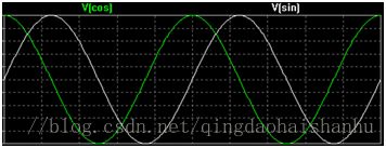
If the phase Ф difference between twosinusoids is 90 degrees (or π /2 radians), then these two signals are said tobe in quadrature. An example of this is the sine wave and the cosine wave.
如果两正弦信号的相位差为90度(或Фπ/ 2弧度),那么这两个信号是正交的。其中一个例子是正弦波和余弦波。
By convention, the cosine wave isin-phase component and the sine wave is the quadrature component. The capitalletter I represents the amplitude of the in-phase signal, and the capitalletter Q represents the amplitude of the quadrature signal.
按照余弦变换,余弦波是同相分量,正弦波是正交分量。大写字母i表示同相信号的振幅,大写字母q表示正交信号的幅度。
Using Quadrature Signals to Modulate
利用正交信号调制
Interesting things happen when you lookat adding quadrature signals together.
If I=1 and Q=0, then you would simplyhave the cosine wave (phase equal to 0). Similarly, if I=0 and Q=1, you would have the sinewave, which is the 90 degree shifted signal.
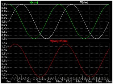
If both I and Q were equal to 1, thenthe sum will be a new signal that is shown graphically below.
Note that adding these two equalamplitude quadrature signals together results in a new sinusoid that is phaseshifted by 45 degrees.
注意,将这两个等幅正交信号叠加在一起,会产生一个新的正弦波,相位偏移为45度。
By now you can see that the amplitudeand the phase of the sum of the quadrature signals is a function of the valueof I and Q. Therefore, you can create modulated RF signals by varying the I andQ values vs. time. Let’s look at a few examples.
现在您可以看到正交信号的和的振幅和相位是i和q的值的函数,因此,可以通过改变i和q值和时间来创建调制的rf信号。让我们看几个例子。
Digital RF Modulation Examples
数字射频调制示例
If Q=0, and I is altered between +1 and-1 over time, you create a Binary Phase Shift Keyed RF signal (BPSK):
如果q=0,并且随着时间的推移,在+ 1和- 1之间改变,则创建一个二进制相移键控rf信号(BPSK):
The I(t) signal could be a simpledigital bit stream. If you have thatsignal control the gain of the RF sinusoid between +1 and -1, you have createda BPSK signal.
i(t)信号可以是简单的数字比特流。如果您的信号控制在1和- 1之间的rf正弦波的增益,那么您已经创建了一个BPSK信号。
Taking this one step further… If twodigital bits are used to control the I and Q values between +1 and -1 overtime, then the resulting sum of the quadrature signals can be one of fourdistinct phases:
再进一步……如果用两个数字位来控制1和- 1之间的i和Q值随着时间的推移,那么正交信号的结果和可以是四个不同的相位之一:
I=+1 & Q=+1 results in 45 degree(度) phase
I=-1 & Q=+1 results in 135degree phase
I=-1 & Q=-1 results in 225degree phase
I=+1 & Q=-1 results in 315degree phase
i = 1和q = 1在315度相位的结果
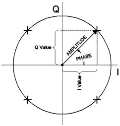
This is known as Quadrature Phase ShiftKeying modulation (QPSK). These are two examples of Quadrature AmplitudeModulation (QAM). The various modulation states for QAM are often shown on aconstellation diagram. A constellation diagram is simply a phasor diagram thatdepicts the amplitude and phase of a signal as a polar plot.
这就是所谓的正交相移键控调制(QPSK)。这是正交幅度调制(QAM)的两个例子。QAM的各种调制状态通常在星座图上显示。星座图是一种简单的相图,它把信号的振幅和相位描绘成极坐标图。
The length of the vector from the originrepresents the signal magnitude, and the angle the vector forms with the horizontalaxis represents the phase. The four “states” for the QPSK signal describedabove are shown as the four “+” symbols in the diagram. You’ll also note thatthe horizontal axis is labeled “I” and the vertical axis is labeled “Q” –because these represent the I and Q component values associated with thesignal.
来自原点的向量的长度表示信号的大小,而矢量以水平轴表示的角度表示相位。上面描述的QPSK信号的四个“状态”被显示为图中的四个“+”符号。您还将注意到水平轴被标记为“i”,纵轴标记为“Q”,因为它们表示与信号相关联的I和Q分量值。
More complex QAM modulations, such as16QAM, simply have more states. For 16QAM, the I and Q values each can have oneof four discrete values, resulting in 16 possible combinations. This results in16 combinations of amplitude and phase for the RF signal.
更复杂的QAM调制,如16QAM,只是有更多的国家。16QAM,I和Q值各有四个离散值,导致16个可能的组合。这导致16个组合的幅度和相位的射频信号。
Quadrature Signals Everywhere
正交信号无处不在
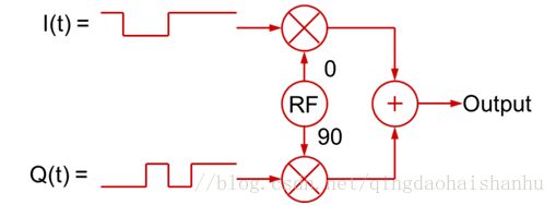
Using I and Q signals that vary overtime to create modulated RF signals is not restricted to digital basebandsignals. The I(t) and Q(t) baseband signals can be analog baseband signalstoo.In fact, in most “digitally” modulated RF applications like QPSK or nQAM, the baseband signals are filtered toslow down the transitions. This is done to limit the resulting bandwidth of themodulated RF signal (fast digital rise/fall times occupy a lot of bandwidth!).These filtered digital signals are effectively analog signals! So, in a moregeneral sense, the quadrature modulation process can be illustrated as shown inthis figure:
使用i和q信号随着时间的变化而产生调制的rf信号并不限于数字基带信号。I(t)和Q(t)的基带信号可以是模拟基带信号。事实上,在大多数的“数字”调制的RF应用如QPSK或质量保证手册,基带信号的滤波减速的过渡。这样做是为了限制调制射频信号产生的带宽(快速数字上升/下降时间占用大量带宽!)这些经过滤波的数字信号是有效的模拟信号!因此,从更一般的意义上来说,正交调制过程可以如图中所示:
The general conclusion you can draw fromthis is that a RF signal with any type of modulation can be created with theappropriate I(t) and Q(t) baseband signals (which in turn vary the amplitudesof the cosine and sine waves that are summed together).
你能得出的一般结论是,用适当的i(t)和q(t)基带信号(依次改变余弦和正弦波相加的振幅),可以产生任何类型调制的rf信号。
Of course, the same process works inreverse to demodulate an RF signal. By mixing an RF signal with LO (localoscillator) signals in quadrature, I(t) and Q(t) baseband signals can becreated.
当然,同一个过程反向工作,以解调射频信号。通过混合RF信号和LO(本地振荡器)信号,可以创建i(t)和q(t)基带信号。
This is the fundamental basis for mostmodern RF signal generation and modulation, as well as demodulation and vectorsignal analysis.
这是现代射频信号产生和调制的基础,也是解调和矢量信号分析的基础。
Software Defined Radio (SDR) systems usethese concepts extensively because the baseband I & Q signals are oftenrepresented as discrete time sampled data. Therefore, digital signal processing(DSP) can be used to literally define the transmitter and receivercharacteristics including filtering, modulation and demodulation, AGC, etc. SDRreceivers often feature a baseband bandwidth of a few hundred kHz or more,giving the ability to perform a wide variety of functions including “wide”bandscope and spectrogram functions, as well as being able to simultaneouslymonitor and demodulate several signals of different types at once.
软件无线电(SDR)系统广泛使用这些概念,因为基带I和Q信号通常被表示为离散时间采样数据。因此,数字信号处理(DSP)可以随便定义发射机和接收机特性包括滤波、调制和解调、AGC等往往采用软件无线电接收机的几百kHz以上基带带宽,提供的能力来执行各种各样的功能,包括“宽”bandscope和谱图的功能,如也可以同时监测解调几个不同类型的信号的一次。
Vector Signal Generators feature aquadrature modulator that accepts I(t) and Q(t) signals which it then uses toamplitude modulate a pair of quadrature sinusoids which are then summed tocreate the modulated RF output. Many Vector Signal Generators generally includepanel jacks where you can connect your own IQ signals. Many include an internalbaseband Arbitrary Waveform Generator (AWG) to create the baseband IQ signals.
矢量信号发生器具有一个正交调制器,它接收i(t)和q(t)信号,然后用它来对一对正交正弦波进行振幅调制,然后将其相加以产生调制的rf输出。许多矢量信号发生器通常包括面板插孔,在那里你可以连接自己的IQ信号。许多包括一个内部基带任意波形发生器(AWG)来创建基带IQ信号。
Modern Vector Signal Analyzers typicallyfeature bandwidths of 25, 40, 110MHz or more. They convert the incoming RFsignals into their I and Q components. All of the analysis (spectral analysisvs. time, demodulation, pulse analysis, etc.) is simply different mathematicalprocessing on the same IQ data. Real-Time Signal Analyzers, such as TektronixRSA5000 and RSA6000 series, have the additional ability to take the “live” IQdata streams and perform real-time processing on the data. This adds theability to do things like visualize the live spectrum of an RF signal, as wellas being able to trigger on transient events that may only be visible in thefrequency domain.
现代矢量信号分析仪的典型特征是带宽的25, 40,110mhz或更多。它们将输入的射频信号转换成它们的I和Q元件。所有的分析(频谱分析与时间,解调,脉冲分析等)是简单的不同的数学处理相同的IQ数据。实时信号分析仪,如泰克rsa5000和rsa6000系列,有额外的能力,以“活”的IQ数据流并对数据进行实时处理。这增加了诸如可视化rf信号的实时频谱以及能够在频域中只可见的瞬态事件的能力。


