STM32H743 RCC时钟部分
摘要
通过输入时钟和输出时钟解析STM32H743的时钟树,并为最小系统程序、PLL动态调整、CPU的外设分配、外设在低功耗模式下的运行、CPU频率的动态调整提供了参考依据。
目录
1 术语
1.1 外设Peripherals
1.2 总线bus和桥bridges
1.3 锁相环PLL
1.4 核心时钟 Kernel clcock
1.5 RCC
1.6 单词/其他
2 输入时钟
2.1 内部震荡器
2.1.1 HSE
2.1.2 HSI
2.2 外部振荡器
2.3 锁相环
3 输出时钟[7.5.1]
3.1 核心时钟 Kernel clcock
3.2 系统时钟 SYS_CK
4 外设分配
4.1 外设分配与核心时钟
4.2 通常情况下的外设分配(CRun):
4.3 低功耗设计:CSleep模式下的外设分配
4.4 低功耗设计:CStop模式下的外设分配
5 本文未说明的功能
6 参考文件
1 术语
1.1 外设Peripherals
手册中的外设分片内外设和片外外设,外设的“外”是相对于CPU而言的。其中片外外设可以是通过SPI和UART连接的传感器芯片。片内外设由可分为两类,一类是如定时器和DMA那样可以仅仅在MCU内部运行,无需与片外外设交互的单元(虽然它们也能和片外外设交互),另一类指如SPI那样的芯片内部用于与外部设备连接的接口电路和总线[4]。按我这样的分类方式,一个片内外设,在不同的功能模式下,就属于不同的子类了。
注:将这个分类是为了后面”核心时钟“的概念做铺垫的。
1.2 总线bus和桥bridges
手册中没有明显区分,总线和桥都指CPU和外设通信的渠道。如:
Clocks for APB (rcc_apb_ck), AHB (rcc_ahb_ck) and AXI (rcc_axi_ck) bridges generated by the RCC.
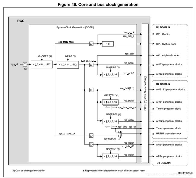
The bus matrix clocks are the clocks provided to the different bridges (APB, AHB or AXI). These clocks are derived from the system clock (sys_ck).
The bus clocks are the bus interface clocks to which the peripherals are connected, it can be APB, AHB or AXI clocks [7.5.8]
per_ck : 为外设设立的一个方便统一调节的逻辑上的时钟。The per_ck clock could be hse_ck, hsi_ker_ck or csi_ker_ck according to CKPERSEL selection.
1.3 锁相环PLL
PLL(Phase Locked Loop): 为锁相回路或锁相环。总体上起到晶振频率倍频的作用,为系统高速率运行提高必要条件。
Sigma-Delta modulator, allowing to fine-tune the VCO frequency by steps of 11 to 0.3 ppm.The Sigma-Delta modulator can be updated on-the-fly, without generating frequency
overshoots on PLLs outputs.[7.5.5]。
VCO(voltage-controlled oscillator):PLL 是锁相环,一个标准的锁相环由 鉴相器,环路滤波器,分频器,压控振荡器(VCO),和晶体构成。VCO 是PLL 里的一个构成部件。[1]
integer mode and fractional mode : 从晶振出来后的频率会不是很准,如HSI可以通过在晶振层面进行频率修正。而为了获取更精确(频率分辨率高)且更准确(与真值的误差小)的频率,可使用小数模式(fractional mode)。与之相对应的整数模式(integer mode)则仅仅将内部或外部振荡器进行整数倍频而已,默认情况下就是这个模式。调整方式详见手册“Figure 45. PLLs Initialization Flowchart”.
1.4 核心时钟 Kernel clcock
原本想翻译把“Kernel”翻译成内核的,但这个时钟明明是由于外设的,总感觉不合理,就把它翻译成“核心了”。具体细节见3.1节。
以例子说明核心时钟的概念。以SPI总线为通信的片外外设芯片A的使用需要两个时钟,第一个时钟为外设接口时钟,为SPI这个片内外设的寄存器和具体硬件逻辑操作提供时钟。第二个时钟是核心时钟(这个时钟通常与总线接口时钟是异步的),为SPI总线中“SLK”线提供时钟,“SLK”线将与片外外设-芯片A。依据如下[7.7.47]及本文3.1节:
Bit 12 SPI1EN: SPI1 Peripheral Clocks Enable
Set and reset by software.
0: SPI1 peripheral clocks disabled (default after reset)
1: SPI1 peripheral clocks enabled:
The peripheral clocks of the SPI1 are: the kernel clock selected by I2S123SRC and provided to
spi_ker_ck input, and the rcc_pclk2 bus interface clock.
1.5 RCC
官方功能定义如[7.5.9]
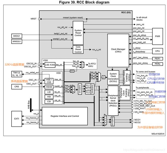
The RCC handles the distribution of the CPU, bus interface and peripheral clocks for the system (D1, D2 and D3 domains),
1.6 单词/其他
| latch |
锁存,数电的概念[2] |
| allocation |
分配;为外设分配一个外设,即通过RCC使能(ativate)一个外设的核心时钟和总线接口时钟。[7.5.9]
|
| SCGU block |
The SCGU block (System Clock Generation Unit) contains several prescalers used to configure the CPU and bus matrix clock frequencies. |
| PKSU block |
The PKSU block (Peripheral Kernel clock Selection Unit) provides several dynamic switches allowing a large choice of kernel clock distribution to peripherals. |
| PKEU、 SCEU |
The PKEU (Peripheral Kernel clock Enable Unit) and SCEU (System Clock Enable Unit) blocks perform the peripheral kernel clock gating, and the bus interface/cores/bus matrix clock gating, respectively [7.5] |
2 输入时钟
2.1 内部震荡器
High-speed external oscillator (HSE) supporting a wide range of crystals from 4 to 48 MHz frequency
Low-speed external oscillator (LSE) for the 32 kHz crystals
2.1.1 HSE
| 方式 |
设置 |
| External Clock source |
1\an external clock source must be provided to OSC_IN pin. 2\ This mode is selected by setting the HSEBYP and HSEON bits of the RCC Source Control Register (RCC_CR) to ‘1’. 3\The external clock source (square, sinus or triangle) with ~50% duty cycle has to drive the OSC_IN pin. |
| External crystal/ceramic resonator |
1\ The oscillator is enabled by setting the HSEBYP bit to ‘0’ and HSEON bit to ‘1’. 2\ The HSE can be used when the product requires a very accurate high-speed clock. The associated hardware configuration is shown in Figure 43: 3\ the resonator and the load capacitors have to be placed as close as possible to the oscillator pins in order to minimizeoutput distortion and startup stabilization time. 4\The loading capacitance values must beadjusted according to the selected crystal or ceramic resonator. |
HSE不能关闭的情形:
1、直接作为系统时钟源
2、作为PLL1的参考时钟源,并且PLL1使能且作为系统时钟源。
自动关闭的情形:系统进入Stop模式或Standby模式
2.1.2 HSI
优势:不需要外部晶振;比HSE更快的启动时间(几微妙)
缺点:即使使用了频率标定,频率准确性依然比外部晶振差。
独特功能:作为HSE失效后的辅助时钟(注在HSE开启式,CSS自动开启;如果CSS检测到HSE失效,产生NMI中断[7.5.3])(可用HSE标定HSI[7.5.8],[P351]);可在Stop模式下运行
it is possible to change the HSIDIV if the HSI is used directly as system clock.
HSIDIV cannot be changed if the HSI is selected as reference clock for at least one enabled PLL (PLLxON bit set to ‘1’). In that case the hardware does not update the HSIDIV with the new value.
HSI不能关闭的情形:
1、直接作为系统时钟源
2、作为PLL1的参考时钟源,并且PLL1使能且作为系统时钟源。
2.2 外部振荡器
High-speed internal oscillator (HSI)
48 MHz RC oscillator (HSI48)
Low-power Internal oscillator (CSI)
Low-speed internal oscillator (LSI)
2.3 锁相环
-
- STM32H7有3个PLL.3个PLL都可以产生外设所需要的时钟,但PLL1才能作为系统时钟源。使用PLL1,可以产生比片内或片外振荡器作为时钟源更丰富的或更高的频率。而PLL2、PLL3称为辅助PLL,可为外设提供时钟源(PLL1也具有这个功能)。
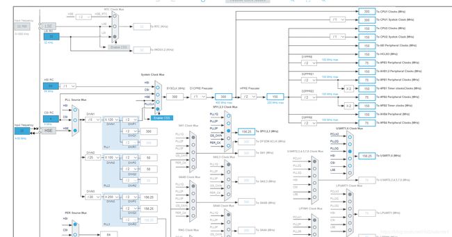
- 每个PLL通过“M”分频,作为VCO的输入,然后通过“N”倍频,倍频后的结果由可分为"R"、“P”、“Q”三路时钟源。设置时钟推荐使用“STM32CubeMX”软件条件,可以省略找寄存器以及其具体位的麻烦事。但看看手册,深入理解时钟树还是有必要的。如果你把经过“M”后的频率(称为参考频率the reference frequency (refx_ck))设置得不在1~16MHz,“RPQ”输出不在150~836MHz时,软件会提示错误,这是由硬件决定的[7.5.5],具体细节有软件把控即可。
- 当复位后,HSI被选择系统时钟,所有PLL关闭。
- 每个PLL都能过还可以对频率进行小数部分的动态调整(change the PLL fractional ratios on-the-fly)。小数部分调整功能默认情况下是不使用的。如需要调整,因为STM32CubeMX不具有该设置,需要自行写代码设置。详见[7.7.13][7.5.5]。
- PL调整:
1、动态调整(tune on-the-fly):只可能在小数模式下调整
When the PLLxRDY goes to ‘1’, it means that the difference between the PLLx output frequency and the target value is lower than ±2%.
3 输出时钟[7.5.1]
时钟树的逻辑主线是从输入时钟到输出时钟。输出时钟的一个重要的树干是系统时钟(sys_ck)。系统时钟分出了CPU时钟和总线矩阵时钟。总线接口时钟觉大多是来源于总线矩阵时钟。最复杂的是核心时钟,它的来源多种多样,导致时钟树显得有点混乱。
下表解释名词,并不完全符合逻辑层次关系。
| 外设时钟 Peripheral clocks
|
|
||||
| CPU时钟 |
The CPU clock is the clock provided to the CPU. It is derived from the system clock (sys_ck). |
||||
| 总线矩阵时钟 |
The bus matrix clocks are the clocks provided to the different bridges (APB, AHB or AXI). These clocks are derived from the system clock (sys_ck) |
3.1 核心时钟 Kernel clcock
1 默认(即系统复位后)内核时钟源:
SPI123SEL-pll1_q_ck
SPI45SEL-rcc_pclk2
SPI6SEL-rcc_pclk4
I2C4SEL-rcc_pclk4
I2C123SEL- rcc_pclk1
UART16SEL-rcc_pclk2
USART2345678SEL-rcc_pclk1
LPUART1SEL-rcc_pclk4
注:为了减少时钟选择开关的数量,一些外围设备共享相同的内核时钟源。然而,所有外围设备都有其专用的启用信号。
2 内核时钟选择依据:
• The PLL1 when the amount of active PLLs has to be reduced
• The PLL2 or 3 for optimal flexibility in frequency generation.PLL2 or PLL3 if better flexibility is required. As an example, this solution allows changing the frequency bus via PLL1 without affecting the speed of some serial interfaces.
• HSE, HSI or CSI for use-cases where the current consumption is critical. HSI or CSI for low-power use-cases or when the peripheral has to quickly wake up from Stop mode (i.e. UART, I2C...).UARTs also need the LSE clock when high baud rates are not required.
• I2S_CKIN when an external clock reference need to be used.
3 内核时钟设计的外设:
| Peripherals dedicated to audio applications |
SAIs : Serial Audio Interface DFSDM :数字滤波 |
| Peripherals dedicated to control and data transfer |
such as SPIs, I2Cs, UARTs SDMMC:Secure digital input/output MultiMediaCard ;接SD卡 QUADSPI:速率比SPI快,可接片外flash FMC:Flexible memory controller;用于扩展片外SDRAM USB:接USB Ethernet:接因特网 ADCs:数模转换 SWPMI:Single Wire Protocol Master Interface Introduction RNG :True random nuber generator FDCAN :高速工业总线 LPTIMs:低功耗定时器 HDMI-CEC:HDMI(High-Definition Multimedia Interface,高清多媒体接口);CEC(Consumer Electronics Control)是一套完整的单总线协议[3] |
| RTC/AWU clock |
RTC: Real-Time Clock实时时钟,用于低功耗设计;主要用于STOP模式下的时间更新 AWU: Auto-Wakeup Unit;主要用于STOP下的唤醒 |
| Watchdog clocks |
看门狗,程序跑飞时复位 |
3.2 系统时钟 SYS_CK
-
- 当复位后,HSI被选择系统时钟,所有PLL关闭。
- 系统时钟源的选择:HSE,HSI,CSI,pll1_p_ck [7.5.6]
- 条件:目标时钟源ready(clock stable after startup delay or PLL locked)
- 查询系统时钟源:The SWS status bits in the RCC Clock Configuration Register (RCC_CFGR)
All the dividers shown in the block diagram can be changed on-the-fly without generating timing violations. This feature is a very simply solution to adapt the busses frequencies to the application needs, thus optimizing the power consumption.
4 外设分配
4.1 外设分配与核心时钟
-
- CPU通过RCC相关寄存器的PERxEN bit来控制外设(时钟)分配。
- CPU在CSleep模式下通过控制PERxLREN bitss来控制外设(时钟)分配。
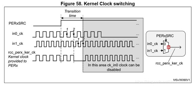
- 时钟切换和阻隔(Gating):a\切换时,两个时钟源都应有效;b\最坏情况下回缺失两个时钟周期;
时钟使能、使能延时:使能最大有2个时钟时期延时;失能最大有1.5个时钟周期延时
-
- 在开启外设(时钟)前,需先确定对应域已经打开。[7.5.10]
The FLASH, AXISRAM, ITCM, DTCM1, DTCM2, SRAM4, IWGD1, IWGD2, PWR, EXTI and RCC are common resources and are implicitly allocated to the CPU. [7.5.9]
![]() 注:还不知道时钟切换产生的时间空隙(即时钟使能延时)会对通信过程产生怎样的影响
注:还不知道时钟切换产生的时间空隙(即时钟使能延时)会对通信过程产生怎样的影响
4.2 通常情况下的外设分配(CRun):
1、开启外设对应的GPIO的复用的功能,以及这些管脚的时钟。
2、开启外设的总线接口时钟和内核时钟并使能(PERxEN)
3、开启CPU与外设相应的NVIC,并使能
4、使用外设:通过配置寄存器(间接的)、调用库函数(直接的)控制外设的通信过程
4.3 低功耗设计:CSleep模式下的外设分配
在CPU_state == CSleep模式下,所有的外设都可以通过设置PERxLREN bits位来保持时钟。虽然CPU不能直接参与外设控制,但可以通到DMA方式来控制外设。(在Csleep模式下,CPU功耗可将为原来的1/2至1/3)
4.4 低功耗设计:CStop模式下的外设分配
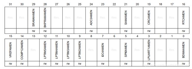
The Autonomous mode allows providing the peripheral clocks to peripherals located in D3, even if the CPU is in CStop mode. When peripheral is enabled, and has its autonomous bit enabled, it receives its peripheral clocks according to D3 domain state, if the CPU is in CStop mode.
需要考虑的有:PERxLPEN位和CPU_state、D3_state、PERxAMEN
Stop模式虽然可以把功耗降到毫安级,但只有部分“L”字号的外设可以通过RCC的自动模式和BDMA来保持超低功耗和数据采集。在RCC D3 Autonomous mode Register (RCC_D3AMR)寄存器上的PERxAMEN位为自动模式(Autonomous mode)使能位,而且这样的Stop模式下的低功耗设置只有STM32L系列和STM32H系列有。
STM32H743仅有如下外设可以使用自动模式:
5 本文未说明的功能
-
- RCC的复位功能[7.4]
- RCC相关的中断和事件[7.6]
- 外设所在的总线的时钟 vs. CPU运行模式及外设状态[7.5.10]
6 参考文件
[1] https://zhidao.baidu.com/question/1829732128904939420.html
[2] https://baike.baidu.com/item/%E9%94%81%E5%AD%98%E5%99%A8/10801965?fr=aladdin
[3] https://blog.csdn.net/ftswsfb/article/details/100183640
[4] https://zhidao.baidu.com/question/1638188465207962380.html
[x.x.x] STM32H743编程手册(文件编号RM0433)的具体章节,下载链接: https://www.st.com/content/st_com/zh/products/microcontrollers-microprocessors/stm32-32-bit-arm-cortex-mcus/stm32-high-performance-mcus/stm32h7-series/stm32h743-753.html#resource
