Verilog初级教程(6)Verilog模块与端口
博文目录
- 写在前面
- 正文
- 模块
- 端口
- 端口类型
- Verilog 1995与Verilog 2001对比
- 参考资料
- 交个朋友
写在前面
前五篇文章已经将Verilog的零碎知识点讲解的差不多了,从这篇开始,就从模块开始了。
模块化设计思想是Verilog的核心,也是数字设计的核心,模块化设计就像搭建积木一样搭建数字电路。
这篇博客,讲解模块使用verilog 2001修订版风格,通过例子是最好的学习方法。
- 个人微信公众号: FPGA LAB
- 个人博客首页
正文
模块
使用Verilog设计数字电路,其实就是设计大大小小的模块,模块相互例化,最后组成一个顶层模块,也就是整个设计了。
下面给出最基本的模块模板:
module module_name(
	input i_clk,
	input i_a,
	input [3:0] i_b,
	input i_en,
	output o_out,
	inout [3:0] o_c
	//your input/ouput/inout ports
);

//your sequential logic
always@(posedge i_clk) begin
//your sequential logic
end

//your combinational logic
always@(*) begin
//your logic
end

assign o_c = i_en ? i_b : 4'hz;
//......

//institation other module
a_module inst(
.i_clk(i_clk),
.i_a(i_a),
.o_c(o_c),
);

endmodule
如果模块内的变量位宽参数化,则模块模板为:
module exam_module #(
parameter c_WIDTH = 8,
parameter c_DEPTH = 16
)(
//input
input i_a,
//inout
inout io_b,
//output
output o_c
);

//the same as before module


endmodule
例化带参数的模块:
module top_module(
// input/output/inout ports define
);

//other logics

//institation module with parameter
exam_module #(
.c_WIDTH(8),
.c_DEPTH(6)
)inst0(
//ports parts
);


endmodule
端口
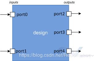
端口是一组信号, 用作特定模块的输入和输出, 并且是与之通信的主要方式。将模块视为放置在 PCB上的预制芯片,很明显,与芯片通信的唯一方法是通过其引脚。端口就像引脚,设计人员将其用于发送和接收来自外界的信号。
端口类型
端口描述
- input 设计模块只能使用其input端口从外部接收值
- output 设计模块只能使用其output端口将值发送到外部
- inout 设计模块可以使用其inout端口发送或接收值
默认情况下,端口类型为wire类型。
语法
  input  [net_type] [range] list_of_names;   // Input port
  inout  [net_type] [range] list_of_names;   // Input & Output port
  output [net_type] [range] list_of_names;   // Output port driven by a wire
  output [var_type] [range] list_of_names;   // Output port driven by a variable
例如:
module  my_design ( input wire      clk,
                    input           en,
                    input           rw,
                    inout [15:0]    data,
                    output           int );

  // Design behavior as Verilog code

endmodule
注:端口名字不能一样,如下是不合规的:
  input  aport;         // First declaration - valid
  input  aport;         // Error - already declared
  output aport;         // Error - already declared
有符号端口声明
可以使用signed属性来声明有符号端口,默认情况下是无符号的端口。
 module (
           input signed a, b,  // a, b are signed from port declaration
           output reg signed c // c is signed from reg declaration
           );

  endmodule
可以参考资料:http://suo.im/5OkJ5D
Verilog 1995与Verilog 2001对比
先看Verilog 1995是如何定义端口的:
Verilog 经过了一些修改, 1995 年的原始 IEEE 版本采用以下方式声明端口。在这里,
模块声明必须首先在方括号内列出端口的名称,然后再在模块主体内定义这些端口的方向。
module test (a, b, c);

  input   [7:0] a;            // inputs "a" and "b" are wires
  input   [7:0] b;
  output   [7:0] c;       // output "c" by default is a wire

  // Still, you can declare them again as wires to avoid confusion
  wire   [7:0] a;
  wire   [7:0] b;
  wire   [7:0] c;
endmodule


module test (a, b, c);

  input  [7:0] a, b;
  output [7:0] c;           // By default c is of type wire

  // port "c" is changed to a reg type
  reg    [7:0] c;
endmodule
Verilog 2001修订:
ANSI-C 样式的端口命名是在 2001 年引入的, 允许在端口列表中指定类型。
module test ( input [7:0]  a,
                            b,     // "b" is considered an 8-bit input
              output [7:0]  c);

  // Design content
endmodule

module test ( input wire [7:0]  a,
              input wire [7:0]  b,
              output reg [7:0]  c);

  // Design content
endmodule
如果端口声明包含网络或变量类型,则认为该端口已完全声明。在网络或变量类型声明中重新声明相同的端口是非法的。
module test ( input      [7:0] a,       // a, e are implicitly declared of type wire
            output reg [7:0] e );

   wire signed [7:0] a;     // illegal - declaration of a is already complete -> simulator dependent
   wire        [7:0] e;     // illegal - declaration of e is already complete

   // Rest of the design code
endmodule
如果端口声明不包含网络或变量类型,则可以再次在网络或变量类型声明中声明端口。
module test ( input      [7:0] a,
              output     [7:0] e);

     reg [7:0] e;              // Okay - net_type was not declared before

     // Rest of the design code
endmodule
参考资料
- 参考资料1
- 参考资料2
- 参考资料3
交个朋友
-
个人微信公众号:FPGA LAB
-
知乎:李锐博恩
-
FPGA/IC技术交流2020
