stm32定时器输出PWM控制LED灯
stm32定时器输出PWM控制LED灯
wangxl@20180723
一、概述
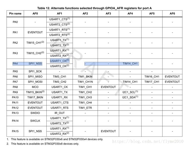
本章中,通过查看原理图,我们的LED指示灯配置在PA4管脚上,查表得知PA4的管脚与TIM14 的通道1重映射, 通过定时器产生 PWM 来控制指示灯的亮度。
二、本章学习目标
- 学会查看数据手册
- 理解stm32端口复用
- 学会配置 STM32 的定时器
- 学会配置定时器输出PWM
三、PA端口复用
参见DataSheet:“STM32F030x数据手册.pdf”P31
复用功能:要想用某个复用功能,首先把IO口配置成复用功能模式,复用输出输入模式(根据功能的不同配置成不同的模式,参考手册里面详细介绍)。比如你想用PA4复用功能TIM14-CH1输出比较,先把PA4设置为推挽复用输出(GPIO_MODE_AF)。再配置TIM14-CH1即可。
Gpio复用功能配置函数介绍:
void GPIO_PinAFConfig(GPIO_TypeDef* GPIOx, uint16_t GPIO_PinSource,uint8_t GPIO_AF)
函数解释:改变指定管脚的映射关系。即配置指定管脚的复用功能。
函数参数说明:
GPIOx:gpio的分组/gpio端口;
GPIO_PinSource:具体要配置成复用功能的管脚(如GPIO_Pin_0 GPIO_Pin_1这样的宏定义);
GPIO_AF:选择该管脚要使用的复用功能。有如下配置:(注意:复用功能的配置要和实际管脚支持的复用功能匹配)
如本例配置:GPIO_PinAFConfig(GPIOA, GPIO_PinSource4, GPIO_AF_4);
四、功能简介
通过初始调用Timer_cfg(),配置PA4管脚对应的tim14时钟;实时调用PWM_cfg(uint8_t duty)函数,传输不同的duty值,改变比较寄存器(CCR1)中的值,从而改变PWM的占空比,实现产生频率为1K占空比的PWM波。
五、代码参考
1、timerpwm.h头
//------------------------timerpwm.h-----------------------------------
#ifndef __TIMERPWM_H
#define __TIMERPWM_H
#include "stm32f0xx.h"
//PA4 TIM14_CH1
extern TIM_OCInitTypeDef TIM_OCInitStructure;
#define LED_PWM_VAL TIM4->CCR1 //CCR1捕获比较值寄存器
#define PWM_PIN GPIO_Pin_4
#define PWM_GPIO_PORT GPIOA
#define PWM_GPIO_CLK RCC_AHBPeriph_GPIOA
void Timer_cfg();
void PWM_cfg(uint8_t duty);
#endif
//------------------------timerpwm.h end-----------------------------------
- Timerpwm.c
#include "timerpwm.h"
uint16_t TimerPeriod;
//初始配置PA4对应的tim14时钟
void Timer_cfg()
{
GPIO_InitTypeDef GPIO_InitStructure;
TIM_TimeBaseInitTypeDef TIM_TimeBaseStructure;
/* GPIOA Clocks enable */
RCC_AHBPeriphClockCmd( PWM_GPIO_CLK, ENABLE);//使能GPIO的AHB总线时钟
/* GPIOA PA4 Configuration: Time4 Channel 1 */
GPIO_InitStructure.GPIO_Pin = PWM_PIN ;
GPIO_InitStructure.GPIO_Mode = GPIO_Mode_AF; //把需要的管脚配置成第二功能模式
GPIO_InitStructure.GPIO_Speed = GPIO_Speed_50MHz;
GPIO_InitStructure.GPIO_OType = GPIO_OType_PP;
GPIO_InitStructure.GPIO_PuPd = GPIO_PuPd_UP ;
GPIO_Init(PWM_GPIO_PORT, &GPIO_InitStructure);//对PA4进行IO口初始化
//配置管脚复用 GPIOA4复用为TIM14
GPIO_PinAFConfig(PWM_GPIO_PORT, GPIO_PinSource4, GPIO_AF_4);
//使能TIM14时钟
RCC_APB1PeriphClockCmd(RCC_APB1Periph_TIM14, ENABLE);
/* Compute the value to be set in ARR regiter to generate signal frequency at 1 Khz */
TimerPeriod = (SystemCoreClock / 1000 ) - 1;
/* Time Base configuration */
TIM_TimeBaseStructure.TIM_Prescaler = 0;
TIM_TimeBaseStructure.TIM_CounterMode = TIM_CounterMode_Up;
TIM_TimeBaseStructure.TIM_Period = TimerPeriod;
TIM_TimeBaseStructure.TIM_ClockDivision = 0;
TIM_TimeBaseStructure.TIM_RepetitionCounter = 0;
//使用内部时钟
TIM_TimeBaseInit(TIM14, &TIM_TimeBaseStructure);
}
//led灯的pwm占空比输出
void PWM_cfg(uint8_t duty)
{
//占空比,取值范围为0-100
int dutyfactor = (uint16_t) (((uint32_t) duty * (TimerPeriod-1 )) / 100);
TIM_OCInitTypeDef TIM_OCInitStructure;
//设置缺省值
TIM_OCStructInit(&TIM_OCInitStructure);
/* Channel 1 Configuration in PWM mode */
TIM_OCInitStructure.TIM_OCMode = TIM_OCMode_PWM2;//选择定时器模式
TIM_OCInitStructure.TIM_OutputState = TIM_OutputState_Enable; //选择输出比较状态 使能输出状态 开启OC*输出到对应引脚
TIM_OCInitStructure.TIM_OutputNState = TIM_OutputNState_Enable;//选择互补输出比较状态 互补输出使能 开启OC*N输出到对应的引脚
TIM_OCInitStructure.TIM_Pulse = dutyfactor; //设置了待装入捕获比较器的脉冲值
//TIM输出比较极性高
TIM_OCInitStructure.TIM_OCPolarity = TIM_OCPolarity_High;//设置TIM输出比较极性 高
TIM_OC1Init(TIM14, &TIM_OCInitStructure);
TIM_Cmd(TIM14, ENABLE);
//设置TIM1的PWM输出为使能
TIM_CtrlPWMOutputs(TIM14,ENABLE);
}

