QDMA 中断
QDMA Interrupt 相关内容
Interrupt Module
The IRQ module aggregates interrupts from various sources into the PCIe® integrated block core interface. The interrupt sources are queue-based interrupts, user interrupts and error interrupts.
Queue-based interrupts and user interrupts are allowed on PFs and VFs, but error interrupts are allowed only on PFs. If the SRIOV is not enabled, each PF has the choice of MSI-X, MSI interrupts, or both. With SRIOV enabled, only MSI-X interrupts are supported across all functions.
Support for MSI-X or MSI interrupts can be specified by attributes. Host system (Root Complex) will enable one or all of the interrupt types supported in hardware. If MSI-X is enabled, it takes precedence over MSI.
The PCIe integrated block core in UltraScale+™ devices offers up to eight interrupts per function. To allow many queues on a given PCIe function and each to have interrupts, the QDMA Subsystem for PCIe offers a novel way of aggregating interrupts from multiple queues to single interrupt vector. In this way, all 2048 queues could in principle be mapped to a single interrupt
vector. QDMA offers 256 interrupt aggregation rings that can be flexibly allocated among the 256 available functions
Interrupts
The QDMA Subsystem for PCIe supports up to 2K total MSI-X vectors. A single MSI-X vector can be used to support multiple queues.
The QDMA supports Interrupt Aggregation. Each vector has an associated Interrupt Aggregation Ring. The QID and status of queues requiring service are written into the Interrupt Aggregation Ring. When a PCIe® MSI-X interrupt is received by the Host, the software reads the Interrupt Aggregation Ring to determine which queue needs service. Mapping of queues to vectors is programmable. It has independent table programming per physical function (PF). It supports MSI/MSI-X interrupt modes for non-SRIOV and MSI-X for SRIOV
Asynchronous and Queue Based Interrupts
The QDMA supports both asynchronous interrupts and queue-based interrupts.
The asynchronous interrupts are used for capturing events that are not synchronous to any DMA operations, namely, errors, status, and debug conditions. There is one asynchronous interrupt per PF. Every asynchronous interrupt is configurable to any one of the PF.
Interrupts are broadcast to all PFs, and maintain status for each PF in a queue based scheme. The queue based interrupts include the interrupts from the H2C MM, H2C stream, C2H MM, and C2H stream.
Interrupt Engine
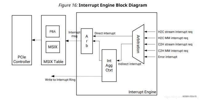
The Interrupt Engine handles the queue based interrupts and the error interrupt.
The following figure shows the Interrupt Engine block diagram
The Interrupt Engine gets the interrupts from H2C MM, H2C stream, C2H MM, C2H stream, or error interrupt
It handles the interrupts in two ways: direct interrupt or indirect interrupt. The interrupt sources has the information that shows if it is direct interrupt or indirect interrupt. It also has the information of the vector. If it is direct interrupt, the vector is the interrupt vector that is used to generate the PCIe MSI-X message (the interrupt vector indix of the MSIX table). If it is indirect interrupt, the vector is the ring index of the Interrupt Aggregation Ring. The interrupt source gets the information of interrupt type and vector from the Descriptor Software Context, the Completion Context, or the error interrupt register
Direct Interrupt
For direct interrupt, the Interrupt Engine gets the interrupt vector from the source, and it then sends out the PCIe MSI-X message directly
Interrupt Aggregation Ring
For the indirect interrupt, it does interrupt aggregation. The following are some restrictions for the interrupt aggregation.
- Each Interrupt Aggregation Ring can only be associated with one function. But multiple rings can be associated with the same function
- It supports up to three messages in the entry per interrupt source
The Interrupt Engine processes the indirect interrupt with the following steps
- Get the aggregation ring index from the interrupt source.
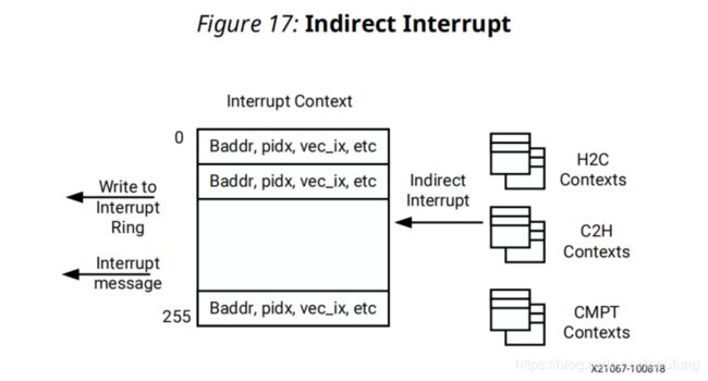
- Look up the Interrupt Context
- Write to the Interrupt Aggregation Ring
- Send out the PCIe MSI-X message
This following figure show the indirect interrupt block diagram.
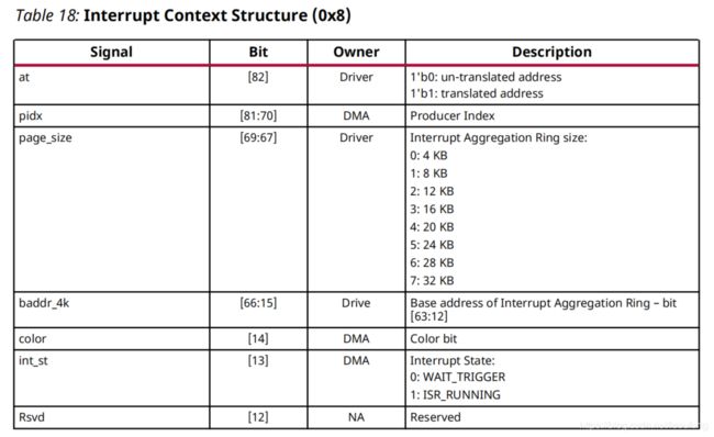
The Interrupt Context includes the information of the Interrupt Aggregation Ring. It has 256 entries to support up to 256 Interrupt Aggregation Rings.
The following is the Interrupt Context Structure (0x8)
The software needs to size the Interrupt Aggregation Ring appropriately. Each source can send up to three messages to the ring. Therefore, the size of the ring needs satisfy the following formula
Number of entry ≥ 3 x number of queues
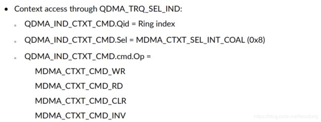
The Interrupt Context is programmed by the context access. The QDMA_IND_CTXT_CMD.Qid has the ring index, which is from the interrupt source. The operation of MDMA_CTXT_CMD_CLR can clear all of the bits in the Interrupt Context. The MDMA_CTXT_CMD_INV can clear the valid bit.
After it looks up the Interrupt Context, it then writes to the Interrupt Aggregation Ring. It also updates the Interrupt Context with the new PIDX, color, and the interrupt state
This is the Interrupt Aggregation Ring entry structure. It has 8B data
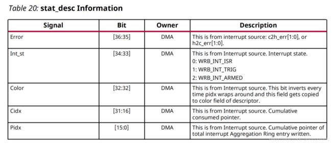
The following is the information in the stat_desc.
When the software allocates the memory space for the Interrupt Aggregation Ring, the coal_color starts with 1'b0. The software needs to initialize the color bit of the Interrupt Context to be 1'b1. When the hardware writes to the Interrupt Aggregation Ring, it reads color bit from the Interrupt Context, and writes it to the entry. When the ring wraps around, the hardware will flip the color bit in the Interrupt Context. In this way, when the software reads from the Interrupt Aggregation Ring, it will know which entries got written by the hardware by looking at the color bit
The software reads the Interrupt Aggregation Ring to get the Qid, and the int_type (H2C or C2H). From the Qid, the software can identify whether the queue is stream or MM
The stat_desc in the Interrupt Aggregation Ring is the status descriptor from the Interrupt source. When the status descriptor is disabled, the software can get the status descriptor information from the Interrupt Aggregation Ring
There can be two cases:
- The interrupt source is C2H stream. Then it is the status descriptor of the C2H Completion Ring. The software can read the pidx of the C2H Completion Ring
- The interrupt source is others (H2C stream, H2C MM, C2H MM). Then it is the status descriptor of that source. The software can read the cidx.
Finally, the Interrupt Engine sends out the PCIe MSI-X message using the interrupt vector from the Interrupt Context.
When the PCIe MSI-X interrupt is received by the Host, the software reads the Interrupt Aggregation Ring to determine which queue needs service. After the software reads the ring, it will do a dynamic pointer update for the software CIDX to indicate the cumulative pointer that the software reads to. The software does the dynamic pointer update using the register QDMA_DMAP_SEL_INT_CIDX[2048] (0x18000). If the software CIDX is equal to the PIDX, this will trigger a write to the Interrupt Context on the interrupt state of that queue. This is to indicate the QDMA that the software already reads all of the entries in the Interrupt Aggregation Ring. If the software CIDX is not equal to the PIDX, it will send out another PCIe MSI-X message. Therefore, the software can read the Interrupt Aggregation Ring again. After that, the software can do a pointer update of the interrupt source ring. For example, if it is C2H stream interrupt, the software will update pointer of the interrupt source ring, which is the C2H Completion Ring
- After the software gets the PCIe MSI-X message, it reads the Interrupt Aggregation Ring entries
- The software uses the coal_color bit to identify the written entries. Each entry has Qid and Int_type (H2C or C2H). From the Qid and Int_type, the software can check if it is stream or MM. This points to a corresponding source ring. For example, if it is C2H stream, the source ring is the C2H Completion Ring. The software can then read the source ring to get information, and do a dynamic pointer update of the source ring after that.
- After the software finishes reading of all written entries in the Interrupt Aggregation Ring, it does one dynamic pointer update of the software cidx using the register QDMA_DMAP_SEL_INT_CIDX[2048] (0x18000). The Qid in the register is the Qid in the last written entry. This communicates to the hardware of the Interrupt Aggregation Ring
pointer used by the software. If the software cidx is not equal to the pidx, the hardware will send out another PCIe MSIX message, so that the software can read the Interrupt Aggregation Ring again.
When the software does the dynamic pointer update for the Interrupt Aggregation Ring using the register QDMA_DMAP_SEL_INT_CIDX[2048] (0x18000), it sends the ring index of the Interrupt Aggregation Ring.
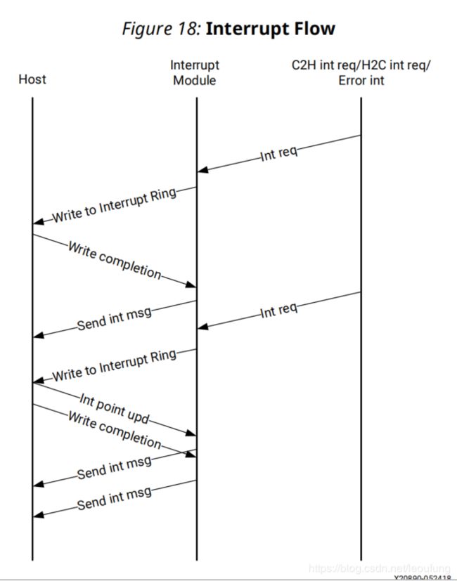
The following diagram shows the indirect interrupt flow. The Interrupt module gets the interrupt requests. It first writes to the Interrupt Aggregation Ring. Then it waits for the write completions. After that, it sends out the PCIe MSI-X message. The interrupt requests can keep on coming, and the Interrupt module keeps on processing them. In the meantime, the software reads the Interrupt Aggregation Ring, and it does the dynamic pointer update. If the software CIDX is not equal to the PIDX, it will send out another PCIe MSI-X message.
Error Interrupt
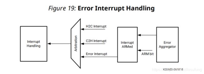
There are Leaf Error Aggregators in different places. They log the errors and propagate the errors to the Central Error Aggregator. Each Leaf Error Aggregator has an error status register and an error mask register. The error mask is enable mask. Only when the error mask is enabled, the Leaf Error Aggregator will propagate the error to the Central Error Aggregator
The Central Error Aggregator aggregates all of the errors together. When any error occurs, it can generate an Error Interrupt if the err_int_arm bit is set in the error interrupt register QDMA_GLBL_ERR_INT (0B04). The err_int_arm bit is set by the software and cleared by the hardware when the Error Interrupt is taken by the Interrupt Engine. The Error Interrupt is for all
of the errors including the H2C errors and C2H errors. The Software must set this err_int_arm bit to generate interrupt again.
The Error Interrupt supports the direct interrupt only. Keep the en_coal bit unset in the error interrupt register QDMA_GLBL_ERR_INT. The interrupt aggregation entry write will be blocked in the case of fatal error such as parity and double bit ECC error causing the QDMA to hang without the software noticing it.
The Error Interrupt gets the vector from the error interrupt register QDMA_GLBL_ERR_INT. For the direct interrupt, the vector is the interrupt vector index of the msix table
Here are the processes of the Error Interrupt
- Reads the Error Interrupt register QDMA_C2H_GLBL_INT (0B04)
- Sends out the PCIe MSI-X message.
The following figure shows the error interrupt register block diagram
Legacy Interrupt
The QDMA Subsystem for PCIe supports the legacy interrupt for physical function, and it is expected that the single queue will be associated with interrupt
To enable the legacy interrupt, the software needs to set the en_lgcy_intr bit in the register QDMA_GLBL_INTERRUPT_CFG (0x288). When en_lgcy_intr is set, the QDMA will not send out the MSI or MSI-X interrupt
When the legacy interrupt wire INTA, INTB, INTC, or INTD is asserted, the QDMA hardware sets the lgcy_intr_pending bit in the QDMA_GLBL_INTERRUPT_CFG (0x288) register. When the software receives the legacy interrupt, it needs to clear the lgcy_intr_pending bit. The hardware will keep the legacy interrupt wire asserted until the software clears the lgcy_intr_pending bit
