SN74HC165驱动
74HC165是并行输入,串行输出,其中SER端也可以作为串行输入,在级联的使用。在使用时候碰到一些问题,解释如下:
1. ABCDEFGH输入后,串行输出,首先输出哪个?
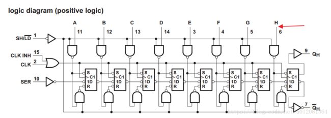
由其逻辑框图可知,H端离输出端最近,且只有一个D触发器,所以第一个输出的是H端,依次输出HGFEDCBA。
2. 如果级联的话,输出顺序是什么?
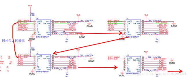
如下图级联所示:
在FPGA中逻辑我们可以这么写:code_temp4 <= {code_temp4[30:0],i_shift_qh4};
其中code_temp4 是寄存器,i_shift_qh4是U10的串行输出端,输出给FPGA
这样的话对于每一片74HC165输出顺序是固定的,为HGFEDCBA,图总级联了四片,其输出顺序为U10-U9-U7-U6,这样最后的数据code_temp4 为:
| 31 | 30 | 29 | 28 | 27 | 26 | 25 | 24 | 23 | 22 | 21 | 20 | 19 | 18 | 17 | 16 | 15 | 14 | 13 | 12 | 11 | 10 | 9 | 8 | 7 | 6 | 5 | 4 | 3 | 2 | 1 | 0 |
| U10 |
U10 |
U10 |
U10 |
U10 |
U10 |
U10 |
U10 | U9 |
U9 |
U9 |
U9 |
U9 |
U9 |
U9 |
U9 | U7 |
U7 |
U7 |
U7 |
U7 |
U7 |
U7 |
U7 | u6 | u6 |
u6 |
u6 |
u6 |
u6 |
u6 |
u6 |
| H | G | F | E | D | C | B | A | H | G | F | E | D | C | B | A | H | G | F | E | D | C | B | A | H | G | F | E | D | C | B | A |
//Serial clock generator
always @(posedge i_clk or negedge i_rstn) beginif(!i_rstn) begin
o_shift_clk <= 1'b0;
counter_divider <= 3'b0;
end
else if(counter_divider >= 3'd4) begin
o_shift_clk <= ~o_shift_clk;
counter_divider <= 3'b0;
end
else begin
o_shift_clk <= o_shift_clk;
counter_divider <= counter_divider + 3'b1;
end
end
//Serial clock edge check
assign rising_edgeof_shiftclk = (clk_temp==2'b01);
assign falling_edgeof_shiftclk = (clk_temp==2'b10);
always @(posedge i_clk or negedge i_rstn) begin
if(!i_rstn) begin
clk_temp <= 2'b0;
end
else begin
clk_temp <= {clk_temp[0],o_shift_clk};
end
end
//Serial data input process
always @(posedge i_clk or negedge i_rstn) begin
if(!i_rstn) begin
o_shift_clkinh <= 1'b1 ;
o_shift_shld_n <= 1'b1 ;
o_code_valid <= 1'b0 ;
o_code <= {28{1'b1}} ;
counter_shift <= 8'h0 ;
state <= IDLE ;
end
else begin
case(state)
IDLE: begin
o_shift_clkinh <= 1'b1 ;
o_shift_shld_n <= 1'b1 ;
o_code_valid <= 1'b0 ;
o_code <= {28{1'b1}} ;
counter_shift <= 8'h0 ;
if(i_start) begin
state <= LOAD ;
end
else begin
state <= IDLE ;
end
end
LOAD: begin
if(rising_edgeof_shiftclk) begin
o_shift_clkinh <= 1'b1 ;
o_shift_shld_n <= 1'b0 ;
state <= LOAD_PULSE ;
end
else begin
state <= LOAD ;
end
end
LOAD_PULSE: begin
if(rising_edgeof_shiftclk) begin
o_shift_clkinh <= 1'b1 ;
o_shift_shld_n <= 1'b1 ;
state <= LOAD_DELAY ;
end
else begin
state <= LOAD_PULSE ;
end
end
LOAD_DELAY: begin
if(rising_edgeof_shiftclk) begin
o_shift_clkinh <= 1'b1 ;
o_shift_shld_n <= 1'b1 ;
state <= SHIFT_START ;
end
else begin
state <= LOAD_DELAY ;
end
end
SHIFT_START: begin
if(falling_edgeof_shiftclk) begin
o_shift_clkinh <= 1'b0 ;
o_shift_shld_n <= 1'b1 ;
state <= SHIFT ;
end
else begin
state <= SHIFT_START ;
end
end
SHIFT: begin
if(falling_edgeof_shiftclk) begin
counter_shift <= counter_shift + 1'b1 ;
if(counter_shift >= 31) begin
o_shift_clkinh <= 1'b1 ;
o_shift_shld_n <= 1'b1 ;
state <= SHIFT_DONE ;
end
end
else begin
state <= SHIFT ;
end
end
SHIFT_DONE: begin
o_shift_clkinh <= 1'b1 ;
o_shift_shld_n <= 1'b1 ;
counter_shift <= 8'h0 ;
o_code_valid <= 1'b1 ;
//o_code <= {code_temp4[3:0],
// code_temp3[7:0],
// code_temp2[7:0],
// code_temp1[7:0]} ;
o_code <= code_temp4[27:0] ;
state <= IDLE ;
end
default: begin
o_shift_clkinh <= 1'b1 ;
o_shift_shld_n <= 1'b1 ;
o_code_valid <= 1'b0 ;
o_code <= {28{1'b1}} ;
counter_shift <= 8'h0 ;
state <= IDLE ;
end
endcase
end
end
always @(posedge i_clk or negedge i_rstn) begin
if(!i_rstn) begin
code_temp4 <= 32'hffff_ffff;
end
else if(o_shift_clkinh==1'b0 && rising_edgeof_shiftclk) begin
code_temp4 <= {code_temp4[30:0],i_shift_qh4};//其中i_shift_qh4是sn165的输出引脚,连接到FPGA
end
else begin
code_temp4 <= code_temp4;
end
end

