OpenGL ES 2.0 - Matrix. setLookAtM/.frustumM/.multiplyMM
最近学习了 opengl es, 要显示3D 的效果,主要对坐标系和位置向量有一个概念.
Matrix.frustumM 透视投影 target
Matrix.setLookAtM 相机位置 camera
Matrix.multiplyMM 矩阵合并 result view
http://web.mit.edu/ruggles/MacData/afs/sipb/project/android/docs/reference/android/opengl/Matrix.html
在OpenGLES环境中,投影和相机视角使你绘制的对象以更接近物理对象的样子显示。这是通过对坐标精确的数学变换实现的。
投影:这种变换跟据所在GLSurfaceView的宽和高调整对象的坐标。如果没有变换,对象会被不规则的视口扭曲。
投射需要在OpenGLview创建或发生变化时调用,在renderer的onSurfaceChanged()方法中
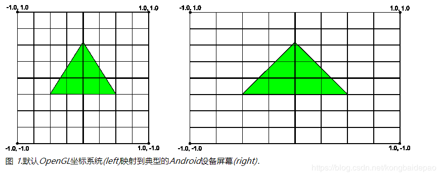
在Android设备中显示图形的一个基本问题是它们的屏幕的尺寸和形状可能不同.OpenGL假设一个正方形的,一致的坐标系统,并且,默认情况下,也乐于把这些坐标画到你的非正方形屏幕上,就像在正方形上一样.
相机视角:变换基于一个"虚拟相机"的位置调整"对象"的坐标。提供了一些工具方法变换绘制对象的显示来模拟一个相机。
一个相机视口的变换只在创建GLSurfaceView时调用,或跟据用户动作动态调用。
一、 Matrix.setLookAtM 设置相机位置 / 设置的是 View矩阵.决定摄影机的空间位置.
 //project 矩阵
 //rmOffset
 public static void setLookAtM(float[] rm, int rmOffset,
            float eyeX, float eyeY, float eyeZ,
            float centerX, float centerY, float centerZ, float upX, float upY,
            float upZ) {

1.1 相机的坐标  -5, 0, 15

eyeX 相机在X轴偏移量(-5左边) , eyey 相机在Y轴偏移量(0),  eyez 相机在Z轴偏移量(15)


1.2 目标的位置  坐标 0,0,0

centerX ,centerY,centerZ  物体中心点,居中一般都是 0,0,0


1.3 相机的视觉向量 (向量有3个属性,一个就是起始点,二个方向,三个就是量)

upx 摄像机UP向量X分量
upy 摄像机UP向量Y分量
upz 摄像机UP向量Z分量
----- up x,y,z----------
(1) 0,1,0
代表相机的起始点和 Y轴 组成的向量, 对应效果图1
(2) 1,0,0
代表相机的起始点和 X轴 组成的向量,对应效果图2
(2) 1,1,0
代表相机的起始点和 X Y 组成的向量,对应效果图3
CX,CY,CZ: -5,0,15 | TX,TY,TZ: 0,0,0
二、Matrix.frustumM 设置透视投影 / 设置的自是Project 投影矩阵, 决定取景时的镜头配置 ,如可视角度, Z距离范围
   public static void frustumM (float[] m, int offset, float left, float right, float bottom, float top, float near, float far)

   Parameters:
       m	the float array that holds the perspective matrix
       offset	the offset into float array m where the perspective matrix data is written
   float left,   //near面的left
   float right,  //near面的right
   float bottom, //near面的bottom
   float top,    //near面的top
   float near,   //near面距离
   float far     //far面距离

   设置这些参数能起到的作用:left,right, bottom,top,这4个参数会影响图像左右和上下缩放比
   (float) width / height
   top和bottom和top会影响上下缩放比,如果left和right已经设置好缩放,
   则bottom只需要设置为-1,top设置为1,这样就能保持图像不变形。
   也可以将left,right 与bottom,top交换比例,即bottom和top设置为 -height/width 和 height/width, left和right设置为-1和1。

   near 和 far 就是一个物体的前面和后面,near和far需要结合拍摄相机即观察者眼睛的位置来设置

   (1) 假如 setLookAtM中设置cx = 0, cy = 0, cz = 20

   float near :

   范围设置 < 20 才能看到绘制图像

   范围设置 > 20,图像就会处于了观察这眼睛的后面,这样绘制的图像就会消失在镜头前,

   float far :

   far参数影响的是立体图形的背面,far一定比near大,一般会设置得比较大,如果设置的比较小,一旦3D图形尺寸很大,这时候由于far太小,
   这个投影矩阵没法容纳图形全部的背面,这样3D图形的背面会有部分隐藏掉的
三、 Matrix.multiplyMM
Multiplies two 4x4 matrices together and stores the result in a third 4x4 matrix. In matrix notation: result = lhs x rhs.
将投影矩阵和相机视图变换矩阵结合的一个方法,生成一个新的矩阵mMVPMatrix。

 public static native void multiplyMM(float[] result, int resultOffset,
            float[] lhs, int lhsOffset, float[] rhs, int rhsOffset);

float[] lhs  project
float[] rhs
result 生成的Result 的矩阵, 就是最终显示在 GLSurfaceView 上的
demo:
  private float[] mProjectMatrix = new float[16];
  private float[] mViewMatrix = new float[16];
  private float[] mResultMatrix = new float[16];

  @Override
  public void onSurfaceCreated(GL10 gl, EGLConfig config) {
        GLES20.glEnable(GLES20.GL_DEPTH_TEST);
  }

  @Override
  public void onSurfaceChanged(GL10 gl, int width, int height) {
	//计算宽高比
        float ratio=(float)width/height;
        //设置透视投影
        Matrix.frustumM(mProjectMatrix, 0, -ratio, ratio, -1, 1, 3, 20);
        //设置相机位置
        Matrix.setLookAtM(mViewMatrix, 0, 0f, 0f, 15f, 0f, 0f, 0f, 0f, 1f, 0.0f);
        //计算变换矩阵
        Matrix.multiplyMM(mResultMatrix,0,mProjectMatrix,0,mViewMatrix,0);
    }


