Android开源项目——自定义圆形图片组件CircularImageView
项目github地址:点击打开链接
控件功能:可以将任意图片裁剪成圆形,控件的大小可以自定义,可以指定图片中心点和半径,也可以添加圆形边框并设置边框的颜色。
使用方法:和使用其他自定义控件没什么区别,这里只需要使用attr.xml中的属性和CircularImageView类文件即可。
下面我列举几种使用情况
1.设置控件大小和图片资源
2.设置控件大小,图片资源和圆心
3.设置控件大小,图片资源,圆心以及半径比例
(注意半径比例不是指实际圆形图片的半径,而是在原始图片上裁剪区域的半径,与上面效果2比较即可看出差别,控件的实际半径我们一般在xml中通过layout_width/layout_height来设置。)
4.设置控件大小,图片资源和边界宽度和颜色
默认宽度是一个像素,颜色是黑色。


5.设置控件大小,图片资源和三层边界的宽度和颜色,默认颜色由内到外分别是黑,白,黑。
(个人感觉设置多层边界这个功能不太实用)
6.设置控件大小,图片资源和两层边界的宽度和颜色
我们都知道在控件的使用大概分两种:xml中添加和在代码中动态添加,我也提供了这两种使用方式。
1.在xml中设置部分属性后,在代码中再设置或修改。(使用setImageBitmap来为控件设置新的Bitmap)
下面的例子我只设置了控件的大小,没有设置控件的图片资源,在代码中设置。
2.在代码中创建CircularImageView对象,然后在代码中添加到View。
Bitmap bm=BitmapFactory.decodeResource(getResources(), R.drawable.pic4);
CircularImageView image1=new CircularImageView(this);
image1.setImageBitmap(bm);
MyLinearLayout linearLayout=new MyLinearLayout(this);
linearLayout.addView(image1, new LayoutParams(400, 400));
setContentView(linearLayout);在CirculatImageView的使用方法上就介绍到这里,下面我来详细描述该控件的实现过程。
CirculatImageView继承自View,重载了View的onMeasurce,onSizeChanged和onDraw函数,来自定义控件的测量和绘制。
CirculatImageView有如下属性,这些属性在attr.xml中设置。
1.圆形头像的属性CircularImageSrc,设置圆形头像的图片资源,我们在该图片的基础上处理得到圆形头像。
2.圆形头像周边可添加圆环,该圆环可以设置其宽度,该圆环包括三个区域:内圆InBorderWidth,环瓤BetweenWidth和外圆OutBorderWidth。,可以分别设置其宽度。圆环的总宽度在BorderWidth中设置。
在使用上,若只设置了圆环总宽度BorderWidth属性,那么只绘制环瓤,不会绘制内圆和外圆。如果未设置内圆宽InBorderWidth和外圆宽OutBorderWidth,那么环瓤BetweenWidth和BorderWidth的作用是一样的。若BetweenWidth和BorderWidth都设置了,使用BorderWidth的值,前者不会起作用的。若只设置了内圆宽InBorderWidth或外圆宽OutBorderWidth,即BetweenWidth和BorderWidth都未设置,那么不会绘制圆环。若只设置了环瓤的宽度和内圆宽度(或外圆宽度),也是会绘制圆环的,两层而已。
3.圆环颜色的设置分为内圆颜色InBorderColor,环瓤颜色BetweenColor和外圆颜色OutBorderColor,如果这三个属性都未设置,那么使用默认的BorderColor值。
4.在将原始图片转换成圆形图片时,可以指定圆形头像中心点,也可以指定半径,这样可以截取原始图片中某个区域用于绘制圆形图片。若不指定半径,那么头像的半径就由图片资源的width/height及中心点与原始图片边界最短距离来共同决定了。
首先来分析一下自定义控件的大小测绘的问题,这是每个自定义控件都会遇到的。
在该控件中有两个大小,一个是所设置原始图片的大小,另一个是该控件的实际大小,我们要做到肯定就是将原始图片进行缩放来满足控件的实际大小。
@Override
public void onMeasure(int widthMeasureSpec, int heightMeasureSpec) {
	int resultWidth = 0;
	int modeWidth = MeasureSpec.getMode(widthMeasureSpec);
	int sizeWidth = MeasureSpec.getSize(widthMeasureSpec);
	if (modeWidth == MeasureSpec.EXACTLY) {
		resultWidth = sizeWidth;
	} else {
		if(srcBitmap!=null){
			// 如果为wrap_content,则比较圆形头像大小和父容器给的最大值sizeWidth
			int length = radius * 2;
			if (modeWidth == MeasureSpec.AT_MOST) {
				resultWidth = Math.min(sizeWidth, length);
			}
		}else{
			//动态添加
			resultWidth=sizeWidth;
		}

	}

	int resultHeight = 0;
	int modeHeight = MeasureSpec.getMode(heightMeasureSpec);
	int sizeHeight = MeasureSpec.getSize(heightMeasureSpec);
	if (modeHeight == MeasureSpec.EXACTLY) {
		resultHeight = sizeHeight;
	} else {
		if(srcBitmap!=null){
			// 如果为wrap_content,则比较圆形头像大小和父容器给的最大值sizeHeight
			int length = radius * 2;
			if (modeHeight == MeasureSpec.AT_MOST) {
				resultHeight = Math.min(sizeHeight, length);
			}
		}else{
			//动态添加
			resultHeight=sizeHeight;
		}
	}

	setMeasuredDimension(resultWidth, resultHeight);
}
我们在绘制之前先在onSizeChanged中获得实际控件的大小。
@Override
public void onSizeChanged(int w, int h, int oldw, int oldh) {
	super.onSizeChanged(w, h, oldw, oldh);
	width = w;
	height = h;
	Log.i(TAG, "width:" + width);
	Log.i(TAG, "height:" + height);
	create();
}
public void create() {
	// 在此处获得裁剪后的Bitmap
	dstBitmap = createDstBitmap();
	// 这里的scaleBitmap本该是圆形的,但可能在createScaledBitmap执行时被width,height拉伸变换
	if(dstBitmap!=null){
		scaleBitmap = Bitmap.createScaledBitmap(dstBitmap, width, height, true);
	}
}scaleBitmap = Bitmap.createScaledBitmap(dstBitmap, width, height, true);//将位图缩放到控件的实际大小@Override
public void onDraw(Canvas canvas) {
super.onDraw(canvas);
if(scaleBitmap!=null){
canvas.drawBitmap(scaleBitmap, 0, 0, null);
}
}1.使用图形混合模式来绘制圆形遮罩。
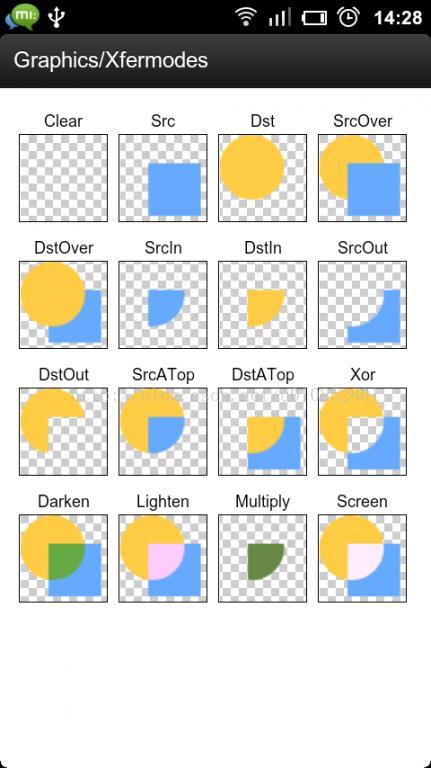
PorterDuff.Mode.DST_IN模式可以只显示图像重叠区域的下层,PorterDuff.Mode.SRC_IN模式可以只显示图像重叠区域的上层,如下图所示。

我们通过设置画笔的Paint的图形混合模式来裁剪出圆形区域,还涉及到Canvas中图层的应用。
// 通过内接矩形来创建圆形遮罩,
public Bitmap createMask() {
	Bitmap bm = Bitmap.createBitmap(radius * 2, radius * 2,
		Bitmap.Config.ARGB_8888);
	Canvas canvas = new Canvas(bm);
	Paint paint = new Paint(1);
	paint.setColor(getResources().getColor(android.R.color.holo_blue_light));
	// 圆所内切的矩形
	RectF rectF = new RectF(0, 0, dstBitmap.getWidth(),
		dstBitmap.getHeight());
	canvas.drawArc(rectF, 0, 360, true, paint);

	return bm;
}这样就得到了一个圆形区域图像。在Canvas图层中将该Bitmap与原始Bitmap重叠以取出重叠区域图像。
// 获得画布后在Canvas进行裁剪
int j = myCanvas.saveLayer(0, 0, radius * 2, radius * 2, null,
		Canvas.ALL_SAVE_FLAG);
int x = centerX - radius;
int y = centerY - radius;
Bitmap bm = Bitmap
		.createBitmap(srcBitmap, x, y, radius * 2, radius * 2);
myCanvas.drawBitmap(bm, 0, 0, mPaint);
mPaint.setXfermode(new PorterDuffXfermode(PorterDuff.Mode.DST_IN));
myCanvas.drawBitmap(createMask(), 0, 0, mPaint);
mPaint.setXfermode(null);
myCanvas.restoreToCount(j);
2.环形边界的绘制(我这里大概描述绘制思路,至于内部的宽度,半径及圆心等计算就不详细陈述了)
这里是在上一步的基础上绘制的,思路和简单,就是直接将空心圆绘制在上面已经绘制好的Canvas上。
if (betweenWidth != 0 || borderWidth != 0) {
	mPaint.setStyle(Paint.Style.STROKE);
	myCanvas.drawBitmap(createBorder(), 0, 0, mPaint);
}public Bitmap createBorder() {
Bitmap bm = Bitmap.createBitmap(radius * 2, radius * 2,
Bitmap.Config.ARGB_8888);
Canvas canvas = new Canvas(bm);
// 未设置内圆和外圆,只绘制环瓤,且该函数的被调用的前提是betweenWidth和borderWidth不全为0
if (outBorderWidth == 0 && inBorderWidth == 0) {
if (betweenWidth != 0 && borderWidth == 0) {
borderWidth = betweenWidth;
}
// 使用borderWidth来画环,半径radius=realRadius-borderWidth/2
borderPaint.setColor(borderColor);
borderPaint.setStrokeWidth(borderWidth);
canvas.drawCircle(radius, radius, radius - borderWidth / 2,
borderPaint);
return bm;
}
// 设置了内圆或外圆,且该函数的被调用的前提是betweenWidth和borderWidth不全为0
if (outBorderWidth != 0 || inBorderWidth != 0) {
// 内圆,环瓤和外圆都要绘制
if (outBorderWidth != 0 && inBorderWidth != 0) {
// 如果环瓤的宽度未设置,则用总宽度borderWidth减去外圆和内圆的宽度
// 若设置了环瓤的宽度,那么总宽度borderWidth的限制就不会起作用了。
if (betweenWidth == 0) {
betweenWidth = borderWidth - inBorderWidth - outBorderWidth;
}
// 外圆的绘制
borderPaint.setColor(outBorderColor);
borderPaint.setStrokeWidth(outBorderWidth);
canvas.drawCircle(radius, radius, radius - outBorderWidth / 2,
borderPaint);
// 环瓤的绘制
borderPaint.setColor(betweenColor);
borderPaint.setStrokeWidth(betweenWidth);
canvas.drawCircle(radius, radius, radius - outBorderWidth
- betweenWidth / 2, borderPaint);
// 内圆的绘制
borderPaint.setColor(inBorderColor);
borderPaint.setStrokeWidth(inBorderWidth);// 宽为2
canvas.drawCircle(radius, radius, radius - outBorderWidth
- betweenWidth - inBorderWidth / 2, borderPaint);
return bm;
}
// 只绘制环瓤和外圆
if (outBorderWidth != 0 && inBorderWidth == 0) {
if (betweenWidth == 0) {
betweenWidth = borderWidth - outBorderWidth;
}
// 外圆的绘制
borderPaint.setColor(outBorderColor);
borderPaint.setStrokeWidth(outBorderWidth);
canvas.drawCircle(radius, radius, radius - outBorderWidth / 2,
borderPaint);
// 环瓤的绘制
borderPaint.setColor(betweenColor);
borderPaint.setStrokeWidth(betweenWidth);
canvas.drawCircle(radius, radius, radius - outBorderWidth
- betweenWidth / 2, borderPaint);
return bm;
}
// 只绘制环瓤和内圆
if (outBorderWidth == 0 && inBorderWidth != 0) {
if (betweenWidth == 0) {
betweenWidth = borderWidth - inBorderWidth;
}
// 环瓤的绘制
borderPaint.setColor(betweenColor);
borderPaint.setStrokeWidth(betweenWidth);
canvas.drawCircle(radius, radius, radius - betweenWidth / 2,
borderPaint);
// 内圆的绘制
borderPaint.setColor(inBorderColor);
borderPaint.setStrokeWidth(inBorderWidth);// 宽为2
canvas.drawCircle(radius, radius, radius - betweenWidth
- inBorderWidth / 2, borderPaint);
return bm;
}
}
return null;
}接口设计
我这里只设计了修改圆形图片位图资源的接口,后面如果有需要,我会添加一些其他接口,比如修改边界颜色和宽度等。
public void setImageBitmap(Bitmap bm){
	if(bm!=null){
		//重新测量和绘制
		srcBitmap=bm;
		init();
		super.requestLayout();
		invalidate();
	}
}
把新的Bitmap赋值给srcBitmap,在init()函数中重新计算新的半径和圆心等值,然后通过调用View的requestLayout函数来使其重新测量measure和布局layout,然后调用invalidate进行重新绘制视图。
我记得好像在github上也有一个开源的圆形头像控件,但是它是通过继承ImageView实现的,且可拓展性也不好。
到这里整个自定义圆形图片控件就完成了,如果有需要改进的地方请各位提出,


