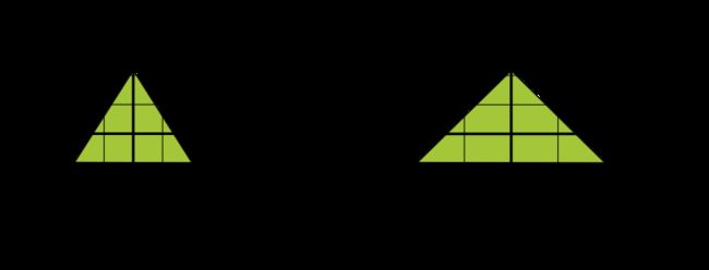
Opengles 2.0 使用Matrix 让三角形、圆形、等不会因为手机的长宽比被拉伸
应用投影和相机视图
在 OpenGL ES 环境中,通过投影和相机视图,显示的绘制对象更接近于眼睛看到的实物。这种对看实物的模拟是通过对绘制对象坐标进行数学转换完成的:
- 投影 - 这种转换可根据显示绘制对象的
GLSurfaceView的宽度和高度调整绘制对象的坐标。如果不进行这种计算,由 OpenGL ES 绘制的对象会被不等比例的视图窗口所扭曲。通常只有在 OpenGL 视图的比例确定下来或在渲染程序的onSurfaceChanged()方法中更改时才需要计算投影转换。如需详细了解 OpenGL ES 投影和坐标映射,请参阅映射绘制对象的坐标。 - 相机视图 - 这种转换可根据虚拟相机的位置调整绘制对象的坐标。请务必注意,OpenGL ES 不会定义实际的相机对象,而是通过转换绘制对象的显示方式来提供模拟相机的实用程序方法。相机视图转换可能仅在您确定
GLSurfaceView时计算一次,也可能会根据用户操作或应用的功能动态变化。
映射已绘制对象的坐标
在 Android 设备上显示图形时,一个的基本问题在于屏幕的尺寸和形状各不相同。OpenGL 假设屏幕采用均匀的方形坐标系,默认情况下,您可以将这些坐标恰当地绘制到通常为非方形的屏幕上,就好像这些屏幕是完美的方形一样。
为了应用投影和相机视图,您可以创建一个投影矩阵和一个相机视图矩阵,并将它们应用到 OpenGL 渲染管道。投影矩阵会重新计算图形的坐标,以便它们能够正确地映射到 Android 设备屏幕。相机视图矩阵会创建一个转换,用于从特定的眼睛位置渲染对象
OpenGL ES 2.0 及更高版本中的投影和相机视图
在 ES 2.0 和 3.0 API 中,您可以应用投影或相机视图,只需先分别向图形对象的顶点着色程序添加投影矩阵或相机视图矩阵成员即可。添加此矩阵成员后,您便可以分别生成投影和相机视图矩阵,并将它们应用到您的对象。
- 为顶点着色程序添加矩阵 - 为视图投影矩阵创建一个变量,并将其作为着色程序位置的调节系数添加。以下顶点着色程序代码示例中包含一个
uMVPMatrix成员,它使您可以将投影和相机视图矩阵应用到使用此着色程序的对象的坐标。
    private final String vertexShaderCode =

        // This matrix member variable provides a hook to manipulate
        // the coordinates of objects that use this vertex shader.
        "uniform mat4 uMVPMatrix;   \n" +

        "attribute vec4 vPosition;  \n" +
        "void main(){               \n" +
        // The matrix must be included as part of gl_Position
        // Note that the uMVPMatrix factor *must be first* in order
        // for the matrix multiplication product to be correct.
        " gl_Position = uMVPMatrix * vPosition; \n" +

        "}  \n";
2.访问着色程序矩阵 - 在顶点着色程序中创建钩子机制以分别应用投影和相机视图后,您可以访问该变量,以应用投影和相机查看矩阵。以下代码展示了如何通过修改 GLSurfaceView.Renderer 实现的 onSurfaceCreated() 方法来访问上述顶点着色程序中定义的矩阵变量。
    public void onSurfaceCreated(GL10 unused, EGLConfig config) {
        ...
        muMVPMatrixHandle = GLES20.glGetUniformLocation(program, "uMVPMatrix");
        ...
    }
3创建投影和相机视图矩阵 - 生成要应用于图形对象的投影和视图矩阵。以下示例代码展示了如何通过修改 GLSurfaceView.Renderer 实现的 onSurfaceCreated() 和 onSurfaceChanged() 方法,根据设备的屏幕宽高比创建相机视图矩阵和投影矩阵。
    public void onSurfaceCreated(GL10 unused, EGLConfig config) {
        ...
        // Create a camera view matrix 填充视图矩阵
        Matrix.setLookAtM(vMatrix, 0, 0, 0, -3, 0f, 0f, 0f, 0f, 1.0f, 0.0f);
    }

    public void onSurfaceChanged(GL10 unused, int width, int height) {
        GLES20.glViewport(0, 0, width, height);

        float ratio = (float) width / height;

        // create a projection matrix from device screen geometry 填充投影矩阵
        Matrix.frustumM(projMatrix, 0, -ratio, ratio, -1, 1, 3, 7);
    }
4应用投影和相机视图矩阵 - 要应用投影和相机视图转换,请将这些矩阵相乘,然后再将它们设置到顶点着色程序中。以下示例代码展示了如何通过修改 GLSurfaceView.Renderer 实现的 onDrawFrame() 方法,合并在上述代码中创建的投影矩阵和相机视图,然后将其应用到将由 OpenGL 渲染的图形对象。
    public void onDrawFrame(GL10 unused) {
        ...
        // Combine the projection and camera view matrices 将投影矩阵和视图矩阵叠加
        Matrix.multiplyMM(vPMatrix, 0, projMatrix, 0, vMatrix, 0);

        // Apply the combined projection and camera view transformations
        //使用前面编译的着色程序应用叠加后的矩阵
        GLES20.glUniformMatrix4fv(muMVPMatrixHandle, 1, false, vPMatrix, 0);

        // Draw objects
        ...
    }
源码
Renderer
public class GLRender_Matrix implements GLSurfaceView.Renderer {

    //    private MatrixTriangle matrixTriangle;
//    private MatrixSquare matrixSquare;
    private float[] vPMatrix = new float[16];
    //camera
    private float[] viewMatrix = new float[16];

    private float[] projectMatrix = new float[16];

    MatrixCircle matrixCircle;

    @Override
    public void onSurfaceCreated(GL10 gl, EGLConfig config) {
        //设置背景颜色
        GLES20.glClearColor(0, 0, 0, 1);
//        matrixTriangle = new MatrixTriangle();
//        matrixSquare = new MatrixSquare();
        matrixCircle = new MatrixCircle(0.4f, 30, 0, 0, 0);
        // Set the camera position (View matrix)
        Matrix.setLookAtM(viewMatrix, 0, 0, 0, -3, 0f, 0f, 0f, 0f, 1.0f, 0.0f);
    }

    @Override
    public void onSurfaceChanged(GL10 gl, int width, int height) {
        GLES20.glViewport(0, 0, width, height);
        float ratial = (float) width / height;
        Matrix.frustumM(projectMatrix, 0, -ratial, ratial, -1, 1, 3, 7);
    }

    @Override
    public void onDrawFrame(GL10 gl) {
        //重新设置背景
        GLES20.glClear(GLES20.GL_COLOR_BUFFER_BIT);

        Matrix.multiplyMM(vPMatrix, 0, projectMatrix, 0, viewMatrix, 0);

        matrixCircle.draw(vPMatrix);
    }
}
public class MatrixCircle {
private FloatBuffer vertexBuffer;
private final String vertexShaderCode =
// This matrix member variable provides a hook to manipulate
// the coordinates of the objects that use this vertex shader
"uniform mat4 uMVPMatrix;" +
"attribute vec4 vPosition;" +
"void main() {" +
// the matrix must be included as a modifier of gl_Position
// Note that the uMVPMatrix factor *must be first* in order
// for the matrix multiplication product to be correct.
" gl_Position = uMVPMatrix * vPosition;" +
"}";
private final String fragmentShaderCode =
"precision mediump float;" +
"uniform vec4 vColor;" +
"void main() {" +
" gl_FragColor = vColor;" +
"}";
private float radius;
private int count;
private float x;
private float y;
private float z;
//顶点的个数
private int vertexCount;
private static final int COORDS_PER_VERTEX = 3;
private static final int vertexStride = COORDS_PER_VERTEX * 4;
private int program;
private int vPMatrixHandle;
private int positionHandle;
private int colorHandle;
float color[] = {0.63671875f, 0.76953125f, 0.22265625f, 1.0f};
public MatrixCircle(float radius, int count, float x, float y, float z) {
this.radius = radius;
this.count = count;
this.x = x;
this.y = y;
this.z = z;
ByteBuffer bb = ByteBuffer.allocateDirect((vertexCount = count + 2) * COORDS_PER_VERTEX * 4);
bb.order(ByteOrder.nativeOrder());
vertexBuffer = bb.asFloatBuffer();
vertexBuffer.put(circleCoords());
vertexBuffer.position(0);
program = GLES20.glCreateProgram();
int vertexShader = GlRender_1.loadShader(GLES20.GL_VERTEX_SHADER, vertexShaderCode);
int fragmentShader = GlRender_1.loadShader(GLES20.GL_FRAGMENT_SHADER, fragmentShaderCode);
GLES20.glAttachShader(program, vertexShader);
GLES20.glAttachShader(program, fragmentShader);
GLES20.glLinkProgram(program);
}
/*
*将360°平均分成n 等份,求每个点的坐标
* */
private float[] circleCoords() {
//将圆形切成n块有n+1个顶点+圆心
float[] coords = new float[vertexCount * COORDS_PER_VERTEX];
int offset = 0;
coords[offset++] = x;
coords[offset++] = y;
coords[offset++] = z;
for (int i = 0; i < count + 1; i++) {
float angleInRadians = ((float) i / (float) count)
* ((float) Math.PI * 2f);
coords[offset++] = x + radius * (float) Math.sin(angleInRadians);
coords[offset++] = y + radius * (float) Math.cos(angleInRadians);
coords[offset++] = z;
}
return coords;
}
public void draw(float[] mvpMatrix) {
GLES20.glUseProgram(program);
vPMatrixHandle = GLES20.glGetUniformLocation(program, "uMVPMatrix");
GLES20.glUniformMatrix4fv(vPMatrixHandle, 1, false, mvpMatrix, 0);
positionHandle = GLES20.glGetAttribLocation(program, "vPosition");
GLES20.glEnableVertexAttribArray(positionHandle);
GLES20.glVertexAttribPointer(positionHandle, COORDS_PER_VERTEX, GLES20.GL_FLOAT, false, vertexStride, vertexBuffer);
colorHandle = GLES20.glGetUniformLocation(program, "vColor");
GLES20.glUniform4fv(colorHandle, 1, color, 0);
GLES20.glDrawArrays(GLES20.GL_TRIANGLE_FAN, 0, vertexCount);
GLES20.glDisableVertexAttribArray(positionHandle);
}
}
总结:绘制二维图形
1.opengles2.0 两种绘制方式 顶点绘制和索引绘制,顶点绘制的模式有设置好的绘制顺序,索引绘制可以自定义绘制顺序
2.只能使用 ByteBuffer.allocateDirect()去分配内存,否则opengles 会报错找不到数组ByteBuffer.allocate()分配的内存是在JVM中,而opengles使用的是系统内存
3.投影矩阵、视图矩阵
