单片机驱动段式液晶屏
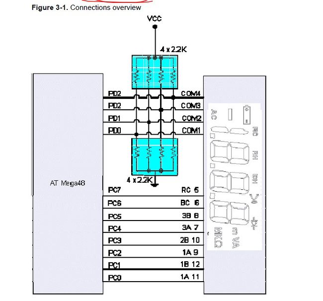
先看看连接图:Notice the pull up resistors on the COM signals: These resistors supply the ½ VCC voltage, which is necessary when a COM signal goes to the Inactive state. The ATmega48 simply sets the respective output pin to an input, and the resistors pull the signal to ½ VCC.
即上拉电阻提供COM需要的1/2VCC电压,当COM对应的单片机引脚为输入的时候,COM为1/2VCC
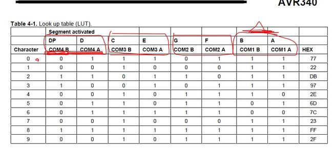
再看一下显示字符0-9所需要的码表,需要COM1(A,B脚输入数据) ,COM2(A,B脚输入数据) ,COM3(A,B脚输入数据) ,COM4(A,B脚输入数据) 全都经过一遍才能显示一个字符

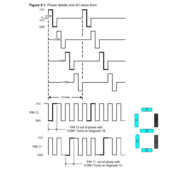
下面是Diagram of COM1-COM4 Signals
The total time for all 4 COMs to cycle is approximately 16 msec, which refreshes the LCD at about a 60 Hz rate.。每个COM高电平持续时间为2ms,用单片机时候需要定时器产生2ms的中断
========================================================
下面程序:Mega48的,明天移植到mega16
// File name: LCX_App_Note_5_3_05.c Demo C code to run Pacific Displays' PPD-332 3 1/2 digit LCD
// Compiled with CodeVision AVR, version 1.24.4a Evaluation version, available from http://www.hpinfotech.ro
// This program displays 4 incrementing decimal digits on the LCD. LCD has 4 COMs and 8 segment connections (12 total)
// COM1-COM4 outputs on PORTD
//Segment Outputs on PORTC, called 1A, 1B, 2A, 2B, 3A, 3B to match A&B values in segment_table array
// The PD-332 has identical LCD wiring for each of 3 digits; 2 segment pins per digit, labeled A and B
#include
unsigned char segs_out = 0;
unsigned char state_counter = 8;
unsigned char output_change = 0;
unsigned char LCD_d_1 =0; // counter starts at "000"
unsigned char LCD_d_2 =0;
unsigned char LCD_d_3 =0;
unsigned char LCD_d_4 =0;
unsigned char Pt_1_sec =0; // 0.1 second counter
// Prototypes defined below
void initialization(void);
#define debug 0
#define LCD_Driver 1
// Look Up Table (LUT) for 3 1/2 digit/4 COM LCD by Pacific Displays, #PD-332
// The following table has 10 entries to display chars 0-9. Hex values are COM1-COM4 for LCD inputs A & B.
const unsigned char segment_table[] = {0x77,0x22,0xDB,0x97,0x2E,0x6D,0x7C,0x23,0xFF,0x2F}; //display numbers 0-9
//************************Timer 0 overflow interrupt service routine***********************
//
interrupt [TIM0_OVF] void timer0_ovf_isr(void)
{
// Re-load Timer 0 value
TCNT0=5; //Timer0 period = 0.125 usec = 8MHZ/64. 2msec = 8 usec*250 5 = 255-250 5/4/05
state_counter++;
output_change = 1; // This is a flag for main loop
if (state_counter > 7)
state_counter = 0;
}
//*********************End of Interrupt Service Routine*************************************
//**********************Main Begins here****************************************************
void main(void)
{
//* * * * * Call Initialization function * * * * * *see function defined below* * * * * * *
initialization();
//* * * * * * * Eanble Global enable interrupts* * * * * * * * ** *
#asm("sei")
//**********The following infinate While Loop contains the Switch statement for LCD refresh******
#if LCD_Driver
while (1)
{
if(output_change)
{
output_change = 0;
// The following state_counter generates the 4 COM output waveforms via PORTD, each with HI and LOW outputs
switch (state_counter)
{
case 0:
{
segs_out = (segment_table[LCD_d_1]& 0x03); //get digit_1's A & B bits
segs_out = segs_out | ((segment_table[LCD_d_2]& 0x03)*4); //get digit_10's A & B bits 乘4即左移2位
segs_out = segs_out | ((segment_table[LCD_d_3]& 0x03)*16); //get digit_100's A & B bits 左移4位
segs_out = segs_out | ((segment_table[LCD_d_4]& 0x03)*64); //get digit_1000's A & B bits 左移6位
DDRD = 0;
PORTD = 0x00;
PORTC = segs_out;
DDRC = 0xFF; // always on
DDRD = 0x01; //COM1 asserted LOW com1 - com4 其它com输入。提供1/2VCC电压
}
break;
case 1:
{
PORTD = 0x01;
PORTC = segs_out ^ 0xFF; // Compliment segment outputs 即 PORTC =~segs_out 取反
DDRC = 0xFF; // always on
DDRD = 0x01; //COM1 asserted High
}
break;
case 2:
{ // 0000 1100
segs_out = (segment_table[LCD_d_1]& 0x0C)/4; //get digit_1's A & B bits
segs_out = segs_out | (segment_table[LCD_d_2]& 0x0C);//get digit_10's A & B bits
segs_out = segs_out | ((segment_table[LCD_d_3]& 0x0C)*4); //get digit_100's A & B bits
segs_out = segs_out | ((segment_table[LCD_d_4]& 0x0C)*16); //get digit_1000's A & B bits
DDRD = 0;
PORTD = 0x00;
PORTC = segs_out;
DDRC = 0xFF; // always on
DDRD = 0x02; //COM2 asserted LOW
}
break;
case 3:
{
PORTD = 0x02;
PORTC = segs_out ^ 0xFF; // Compliment segment outputs
DDRC =0xFF;
DDRD = 0x02; //COM2 asserted High
}
break;
case 4:
{ //0011 0000
segs_out = (segment_table[LCD_d_1]& 0x30)/16; //get digit_1's A & B bits
segs_out = segs_out | ((segment_table[LCD_d_2]& 0x30)/4);//get digit_10's A & B bits
segs_out = segs_out | (segment_table[LCD_d_3]& 0x30);//get digit_100's A & B bits
segs_out = segs_out | ((segment_table[LCD_d_4]& 0x30)*4);//get digit_1000's A & B bits
DDRD = 0;
PORTD = 0x00;
PORTC = segs_out;
DDRC = 0xFF;
DDRD = 0x04; //COM3 asserted LOW
}
break;
case 5:
{
PORTD = 0x04;
PORTC = segs_out ^ 0xFF; // Compliment segment outputs
DDRC = 0xFF;
DDRD = 0x04; //COM3 asserted High
}
break;
case 6:
{
segs_out = (segment_table[LCD_d_1]& 0xC0)/64; //get digit_1's A & B bits
segs_out = segs_out | ((segment_table[LCD_d_2]& 0xC0)/16); //get digit_10's A & B bits
segs_out = segs_out | ((segment_table[LCD_d_3]& 0xC0)/4); //get digit_100's A & B bits
segs_out = segs_out | (segment_table[LCD_d_4]& 0xC0); //get digit_1000's A & B bits
DDRD = 0;
PORTD = 0x00;
// PORTC = 0x00;//LCD_d_3 ^ 0xFF;
PORTC = segs_out;
DDRC = 0xFF;
DDRD = 0x08; //COM4 asserted LOW
}
break;
case 7:
{
PORTD = 0x08;
PORTC = 0x55;
// PORTC = 0xFF; //LCD_d_3;
PORTC = segs_out ^ 0xFF; // Compliment segment outputs
DDRC = 0xFF;
DDRD = 0x08; //COM4 asserted High
}
break;
default: DDRC = 0;
DDRD = 0; // COM1-COM4 float
}
// Increment a counter to measure out 0.1 sec
Pt_1_sec++;
if (Pt_1_sec >=50)
{//.1 sec
Pt_1_sec = 0;
LCD_d_1++; // 3 1/2 digit ripple BCD counter for LCD digits
if (LCD_d_1 >=10)
{
LCD_d_1 = 0;
LCD_d_2++;
}
if (LCD_d_2 >=10)
{
LCD_d_2 = 0;
LCD_d_3++;
}
if (LCD_d_3 >=10)
{
LCD_d_3 = 0;
LCD_d_4++;
}
}// end .1 sec
} // ****************End of Switch Statement************************
}//the end of while
#endif
//***********************End of infinite While loop**********************************
}
//***********************End of Main*************************************************
//************************Initialization function defined here***********************
void initialization(void)
{
// Declare your local variables here
// Crystal Oscillator division factor: 1
CLKPR=0x80;
CLKPR=0x00;
//DDRC=0x7F; //7 Segment outputs
// Timer/Counter 0 initialization
TCCR0A=0x00;
TCCR0B=0x03; // = 8MHz/64 3/22/05
TCNT0=0xC1;
// External Interrupt(s) initialization
// INT0: Off
// INT1: Off
// Interrupt on any change on pins PCINT0-7: Off
// Interrupt on any change on pins PCINT8-14: Off
// Interrupt on any change on pins PCINT16-23: Off
EICRA=0x00;
EIMSK=0x00;
PCICR=0x00;
// Timer/Counter 0 Interrupt(s) initialization
TIMSK0=0x01;
// Timer/Counter 1 Interrupt(s) initialization
TIMSK1=0x00;
// Timer/Counter 2 Interrupt(s) initialization
TIMSK2=0x00;
//Analog Comparator initialization
// Analog Comparator: Off
// Analog Comparator Input Capture Dy Timer/Counter 1: Off
//************************End of Initialization function ***************************
}
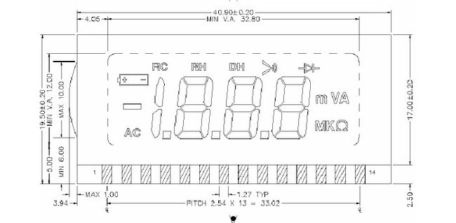
补上液晶图


