5-The Link Layer. Links, Access Networks, and LANs
Please indicate the source: http://blog.csdn.net/gaoxiangnumber1
Welcome to my github: https://github.com/gaoxiangnumber1
- Two fundamentally different types of link-layer channels.
- Broadcast channels: connect multiple hosts in wireless LANs, satellite networks, and hybrid fiber-coaxial cable(HFC) access networks. Since many hosts are connected to the same broadcast communication channel, a medium access protocol is needed to coordinate frame transmission.
- Point-to-Point communication link: such as between two routers connected by a long-distance link.
5.1 Introduction to the Link Layer
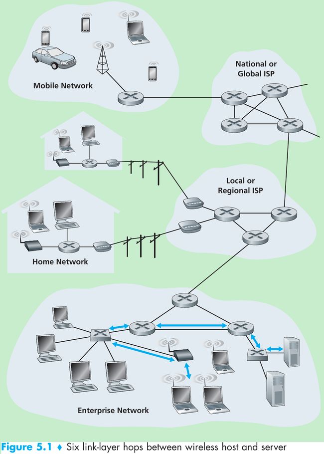
- Figure 5.1, consider sending a datagram from one of the wireless hosts to one of the servers. This datagram will pass through six links:
- a WiFi link between sending host and WiFi access point,
- an Ethernet link between the access point and a link-layer switch;
- a link between the link-layer switch and the router,
- a link between the two routers;
- an Ethernet link between the router and a link-layer switch;
- finally an Ethernet link between the switch and the server.
Over a given link, a transmitting node encapsulates the datagram in a link-layer frame and transmits the frame into the link.
5.1.1 The Services Provided by the Link Layer
- Framing. Almost all link-layer protocols encapsulate each network-layer datagram within a link-layer frame before transmission over the link. A frame consists of a data field, in which the network-layer datagram is inserted, and a number of header fields. The structure of the frame is specified by the link-layer protocol.
- Link access. A medium access control(MAC) protocol specifies the rules by which a frame is transmitted onto the link. For point-to-point links that have a single sender at one end of the link and a single receiver at the other end of the link, the MAC protocol is simple: the sender can send a frame whenever the link is idle. When multiple nodes share a single broadcast link(multiple access problem), the MAC protocol serves to coordinate the frame transmissions of the many nodes.
- Reliable delivery. This service guarantees to move each network-layer datagram across the link without error. It is often used for links that are prone to high error rates(wireless link…) with the goal of correcting an error locally(on the link where the error occurs) rather than forcing an end-to-end retransmission of the data by a transport- or application-layer protocol.
- Error detection and correction. This is done by having the transmitting node include error-detection bits in the frame, and having the receiving node perform an error check. Error correction is that a receiver detects determines where in the frame the errors have occurred and then corrects these errors.
5.1.2 Where Is the Link Layer Implemented?
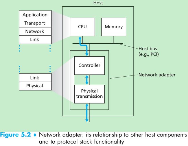
- Figure 5.2. The link layer is implemented in a network adapter(also known as network interface card(NIC)). At the heart of the network adapter is the link-layer controller, usually a single, special-purpose chip that implements many of the link-layer services. So, much of a link-layer controller’s functionality is implemented in hardware.
- On the sending side, the controller takes a datagram that has been created and stored in host memory by the higher layers of the protocol stack, encapsulates the datagram in a link-layer frame(filling in the frame’s various fields), and then transmits the frame into the communication link, following the link-access protocol.
- On the receiving side, a controller receives the entire frame, and extracts the network-layer datagram. If the link layer performs error detection, then it is the sending controller that sets the error-detection bits in the frame header and it is the receiving controller that performs error detection.
- Figure 5.2 shows that while most of the link layer is implemented in hardware, part of the link layer is implemented in software that runs on the host’s CPU. The software components of the link layer implement higher-level link-layer functionality such as assembling link-layer addressing information and activating the controller hardware. On the receiving side, link-layer software responds to controller interrupts(e.g., due to the receipt of one or more frames), handling error conditions and passing a datagram up to the network layer.
- Summary: the link layer is a combination of hardware and software.
5.2 Error-Detection and -Correction Techniques

- Figure 5.3. At the sending node, data D to be protected against bit errors is augmented with error-detection and -correction bits(EDC). Both D and EDC are sent to the receiving node in a link-level frame. At the receiving node, a sequence of bits, D’ and EDC’ is received. The receiver’s challenge is to determine whether or not D’ is the same as the original D, given that it has only received D’ and EDC’.
- Error-detection and -correction techniques allow the receiver to detect that bit errors have occurred. But there still may be undetected bit errors.
- Let’s examine three techniques for detecting errors in the transmitted data: parity checks(illustrate the basic ideas behind error detection and correction), checksumming methods(typically used in the transport layer), and cyclic redundancy checks(typically used in the link layer in an adapter).
5.2.1 Parity Checks
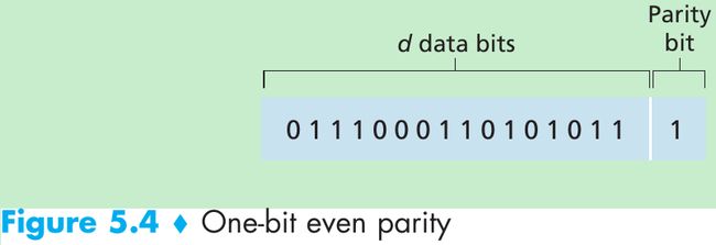
- Suppose that the information to be sent has d bits.
- For even parity scheme, the sender includes one additional bit and chooses its value such that the total number of 1s in the d + 1 bits(the original information plus a parity bit) is even.
- For odd parity scheme, the parity bit value is chosen such that there is an odd number of 1s.
- The receiver need count the number of 1s in the received d + 1 bits.
- If an odd number of 1-valued bits are found with an even parity scheme, the receiver knows that some odd number of bit errors have occurred.
- But even number of bit errors would result in an undetected error. Measurements have shown that errors are often clustered together in bursts. Under burst error conditions, the probability of undetected errors in a frame protected by single-bit parity can approach 50 percent.

- Figure 5.5 shows a two-dimensional generalization of the single-bit parity scheme. The d bits in D are divided into i rows and j columns. A parity value is computed for each row and for each column. The resulting i + j + 1 parity bits comprise the link-layer frame’s error-detection bits.
- Suppose that a single bit error occurs in the original d bits of information. With this two-dimensional parity scheme, the parity of both the column and the row containing the flipped bit will be in error. The receiver can use the indices of the column and row with parity errors to identify the bit that was corrupted and correct that error. Two-dimensional parity can also detect but not correct any combination of two errors in a packet.
- The ability of the receiver to both detect and correct errors is known as forward error correction(FEC). FEC allows for immediate correction of errors at the receiver, thus decrease the number of sender retransmissions required.
5.2.2 Checksumming Methods
- The Internet checksum treats bytes of data as 16-bit integers and sum them. The 1s complement of this sum then forms the Internet checksum that is carried in the segment header. The receiver checks the checksum by taking the 1s complement of the sum of the received data(including the checksum) and checking whether the result is all 1 bits. If any of the bits are 0, an error is indicated.
- In TCP and UDP, the Internet checksum is computed over all fields(header and data fields included); in IP, the checksum is computed only over the IP header.
- Checksumming methods provide relatively weak protection against errors as compared with cyclic redundancy check. Why is checksumming used at the transport layer and cyclic redundancy check used at the link layer?
- Because transport-layer error detection is implemented in software, it is important to have a simple and fast error-detection scheme such as checksumming.
- Error detection at the link layer is implemented in dedicated hardware in adapters, which can rapidly perform the more complex CRC operations.
5.2.3 Cyclic Redundancy Check(CRC)
- CRC codes are also known as polynomial codes, since it is possible to view the bit string to be sent as a polynomial whose coefficients are the 0 and 1 values in the bit string, with operations on the bit string interpreted as polynomial arithmetic.
- Consider the d-bit piece of data, D, that the sending node wants to send. The sender and receiver must first agree on an r + 1 bit generator, G. We require that the leftmost bit of G be 1. Figure 5.6.
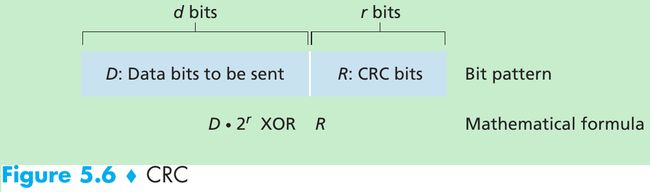
- For a given piece of data, D, the sender will choose r additional bits, R, and append them to D such that the resulting d + r bit pattern is exactly divisible by G(i.e., has no remainder) using modulo-2 arithmetic.
- The process of error checking with CRC: The receiver divides the d + r received bits by G. If the remainder is nonzero, an error has occurred; otherwise the data is accepted as being correct.
- All CRC calculations are done in modulo-2 arithmetic without carries in addition or borrows in subtraction. This means that addition and subtraction are identical, and both are equivalent to the bitwise exclusive-or(XOR) of the operands.
1011 - 0101 = 1011 XOR 0101 = 1110
1001 - 1101 = 1001 XOR 1101 = 0100 - Multiplication and division are the same as in base-2 arithmetic, except that any required addition or subtraction is done without carries or borrows. Given D and R, the quantity D * 2r XOR R yields the d + r bit pattern shown in Figure 5.6.
- We want to choose R such that G divides into D * 2r XOR R without remainder. If we XOR R to both sides of the above equation, we get D * 2r = nG XOR R.
This equation tells us that if we divide D * 2r by G, the value of the remainder is precisely R. So, we can calculate R as R = remainder(D * 2r / G).

- Figure 5.7. D = 101110, d = 6, G = 1001, and r = 3. The 9 bits transmitted in this case are 101110 011.
- International standards have been defined for 8-, 12-, 16-, and 32-bit generators. The CRC-32 32-bit standard uses a generator of
GCRC-32 = 100000100110000010001110110110111 - Each of the CRC standards can detect burst errors of fewer than r + 1 bits. This means that all consecutive bit errors of r bits or fewer will be detected. Under appropriate assumptions, a burst of length greater than r + 1 bits is detected with probability 1 - 0.5r. Also, each of the CRC standards can detect any odd number of bit errors.
5.3 Multiple Access Links and Protocols
- Two types of network links: point-to-point links and broadcast links. Broadcast link can have multiple sending and receiving nodes all connected to the same, single, shared broadcast channel. Broadcast means when any one node transmits a frame, the channel broadcasts the frame and each of the other nodes receives a copy. Computer networks have multiple access protocols by which nodes regulate their transmission into the shared broadcast channel.
- Because all nodes are capable of transmitting frames, more than one node can transmit frames at the same time. When this happens, all of the nodes receive multiple frames at the same time. But none of the receiving nodes can make any sense of any of the frames that were transmitted. Thus, all the frames involved in the collision are lost, and the broadcast channel is wasted during the collision interval.
- The coordination for the transmissions of the active nodes is the responsibility of the multiple access protocol. Any multiple access protocol belongs to one of three categories: channel partitioning protocols, random access protocols, and taking turns protocols.
- Ideally, a multiple access protocol for a broadcast channel of rate R bits per second should have the following characteristics:
- When only one node has data to send, that node has a throughput of R bps.
- When M nodes have data to send, each of these nodes has a throughput of R/M bps. This need not necessarily imply that each of the M nodes always has an rate of R/M, but rather that each node should have an average transmission rate of R/M over defined interval of time.
- The protocol is decentralized: there is no master node that represents a single point of failure for the network.
- The protocol is simple, so that it is inexpensive to implement.
5.3.1 Channel Partitioning Protocols
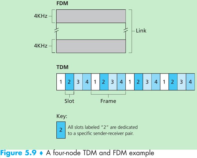
- Time-division multiplexing(TDM) and frequency-division multiplexing(FDM) are two techniques that can be used to partition a broadcast channel’s bandwidth among all nodes sharing that channel. Suppose the channel supports N nodes and the transmission rate of the channel is R bps.
- TDM divides time into time frames and divides each time frame into N time slots. Each time slot is then assigned to one of the N nodes. Whenever a node has a packet to send, it transmits the packet’s bits during its assigned time slot. Typically, slot sizes are chosen so that a single packet can be transmitted during a slot time. Figure 5.9 shows a four-node TDM example.
- Pros:
- Eliminates collisions.
- Fair: each node gets a transmission rate of R/N bps.
Cons: - A node is limited to an average rate of R/N bps even when it is the only node with packets to send.
- A node must wait for its turn in the transmission sequence even when it is the only node with frame to send.
- FDM divides the R bps channel into different frequencies(each with a bandwidth of R/N) and assigns each frequency to one of the N nodes. FDM creates N smaller channels of R/N bps out of the single, larger R bps channel. FDM shares both the advantages and drawbacks of TDM.
- A third channel partitioning protocol is code division multiple access(CDMA). CDMA assigns a different code to each node. Each node then uses its unique code to encode the data bits it sends. If the codes are chosen carefully, different nodes can transmit simultaneously and have their respective receivers correctly receive a sender’s encoded data bits in spite of interfering transmissions by other nodes.
5.3.2 Random Access Protocols
- In random access protocol:
- A transmitting node transmits at the full rate of the channel.
- When a node experiences a collision, it waits an independent random delay with other nodes before retransmitting the frame, therefore it is able to sneak its frame into the channel without a collision.
Slotted ALOHA
- Assume:
• All frames consist of exactly L bits.
• Time is divided into slots of size L/R seconds(i.e., a slot equals the time to transmit one frame).
• Nodes start to transmit frames only at the beginnings of slots.
• The nodes are synchronized so that each node knows when the slots begin.
• If two or more frames collide in a slot, then all the nodes detect the collision event before the slot ends. - The operation of slotted ALOHA in each node:
- When the node has a fresh frame to send, it waits until the beginning of the next slot and transmits the entire frame in the slot.
- If there isn’t a collision, the node has successfully transmitted its frame and need not retransmit the frame.
- If there is a collision, the node detects the collision before the end of the slot. The node retransmits its frame in each subsequent slot with probability p until the frame is transmitted without a collision.
- The event heads corresponds to “retransmit” which occurs with probability p, the event tails corresponds to “skip the slot and toss the coin again in the next slot” which occurs with probability(1 - p). All nodes involved in the collision toss their coins independently.
- Advantages.
- Unlike channel partitioning, it allows a node to transmit continuously at the full rate when that node is the only active node(A node is said to be active if it has frames to send).
- It is decentralized because each node detects collisions and independently decides when to retransmit.(But it requires the slots to be synchronized in the nodes; we’ll discuss an unslotted version of the ALOHA protocol and CSMA protocols that don’t require such synchronization.)
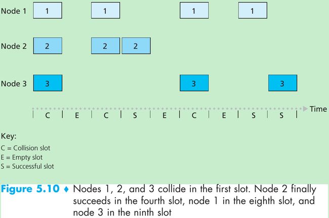
- Figure 5.10: When there are multiple active nodes, a fraction of the slots will have collisions and will be wasted; another fraction of the slots will be empty because all active nodes refrain from transmitting; the only successful slots will be those in which exactly one node transmits.
- The efficiency of a slotted multiple access protocol is defined to be the long-run fraction of successful slots in the case when there are a large number of active nodes, each always having a large number of frames to send.
- Suppose there are N nodes, then the probability that a given slot is successful is the probability that one of the nodes transmits and the remaining N - 1 nodes don’t transmit: Np(1 - p)N-1. The maximum efficiency of the protocol is 0.37.
Aloha
- The slotted ALOHA protocol required that all nodes synchronize their transmissions to start at the beginning of a slot. In pure ALOHA, when a frame first arrives(i.e., a network-layer datagram is passed down from the network layer at the sending node), the node immediately transmits the frame in its entirety into the broadcast channel.
- If a transmitted frame experiences a collision, the node will then immediately retransmit the frame with probability p.
- Otherwise, the node waits for a frame transmission time and then transmits the frame with probability p, or waits for another frame time with probability 1 - p.
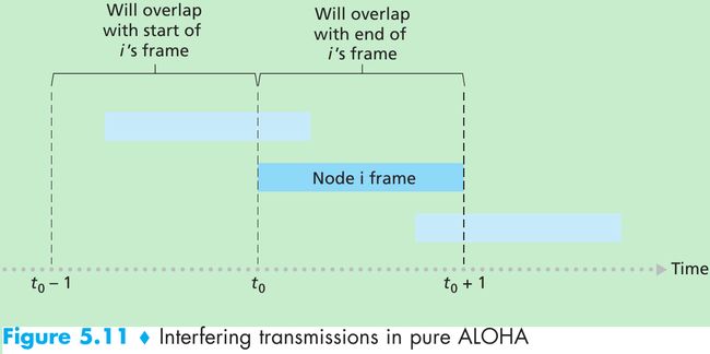
- Figure 5.11. Suppose node begins transmission at time t0.
- In order for this frame to be successfully transmitted, no other nodes can begin their transmission in the interval of time [t0 - 1, t0] because such a transmission would overlap with the beginning of the transmission of node i’s frame. The probability that all other nodes don’t begin a transmission in this interval is(1 - p)N-1.
- No other node can begin a transmission while node i is transmitting, as such a transmission would overlap with the latter part of node i’s transmission. The probability is also (1 - p)N-1.
The probability that a given node has a successful transmission is p(1 - p)2(N-1). The maximum efficiency of the pure ALOHA protocol is 1/(2e), half that of slotted ALOHA.
Carrier Sense Multiple Access(CSMA)
- Two rules embodied in the carrier sense multiple access(CSMA) and CSMA with collision detection(CSMA/CD) protocols.
- Carrier Sensing: a node listens to the channel before transmitting. If a frame from another node is currently being transmitted into the channel, a node then waits until it detects no transmissions for a short amount of time and then begins transmission.
- Collision Detection: a transmitting node listens to the channel while it is transmitting. If it detects that another node is transmitting an interfering frame, it stops transmitting and waits a random amount of time before repeating the sense-and-transmit-when-idle cycle.
Why do collisions occur if all nodes perform carrier sensing?
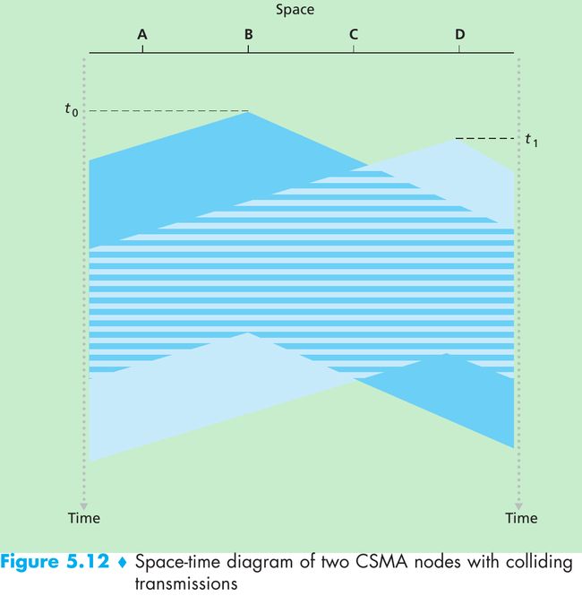
- Figure 5.12 shows a space-time diagram of four nodes(A, B, C, D) attached to a linear broadcast bus. The horizontal axis shows the position of each node in space; the vertical axis represents time.
- At time t0, node B senses the channel is idle, thus it begins transmitting with its bits propagating in both directions along the broadcast medium.
- At time t1(t1 > t0), node D has a frame to send. Although node B is currently transmitting at time t1, the bits being transmitted by B have yet to reach D, and thus D senses the channel idle at t1. D thus begins transmitting its frame.
- A short time later, B’s transmission begins to interfere with D’s transmission at D. The end-to-end channel propagation delay of a broadcast channel will play a crucial role in determining its performance. The longer this propagation delay, the larger the chance that a carrier-sensing node is not yet able to sense a transmission that has already begun at another node in the network.
Carrier Sense Multiple Access with Collision Detection(CSMA/CD)
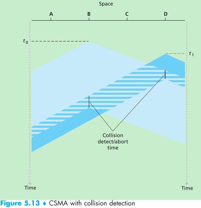
- In Figure 5.12, nodes don’t perform collision detection: both B and D continue to transmit their frames in their entirety even though a collision has occurred. When a node performs collision detection, it ceases transmission as soon as it detects a collision.
- n Figure 5.13, nodes each abort their transmission a short time after detecting a collision. Adding collision detection to a multiple access protocol help protocol performance by not transmitting a useless, damaged(by interference with a frame from another node) frame in its entirety.
- Operations from the perspective of an adapter in a node attached to a broadcast channel:
- The adapter obtains a datagram from the network layer, prepares a link-layer frame, and puts the frame adapter buffer.
- If the adapter senses that the channel is idle, it starts to transmit the frame; otherwise, it waits until it senses no signal energy and then starts to transmit the frame.
- While transmitting, the adapter monitors for the presence of signal energy coming from other adapters using the broadcast channel.
- If the adapter transmits the entire frame without detecting signal energy from other adapters, the adapter is finished with the frame; otherwise, it stops transmitting its frame.
- After aborting, the adapter waits a random amount of time and returns to step 2. The random amount of time should be short when the number of colliding nodes is small, and long when the number of colliding nodes is large.
- The binary exponential backoff algorithm(used in Ethernet): When transmitting a frame that has already experienced n collisions, a node chooses the value of K at random from {0, 1, 2, … . 2n - 1}.
For Ethernet, the actual amount of time a node waits is K * 512 bit times(i.e., K times the amount of time needed to send 512 bits into the Ethernet) and the maximum value that n can take is 10.
Each time a node prepares a new frame for transmission, it runs the CSMA/CD algorithm, not taking into account any collisions that may have occurred in the recent past.
CSMA/CD Efficiency
- We define the efficiency of CSMA/CD to be the long-run fraction of time during which frames are being transmitted on the channel without collisions when there is a large number of active nodes, with each node having a large number of frames to send.
- d-prop denote the maximum time it takes signal energy to propagate between any two adapters.
d-trans be the time to transmit a maximum-size frame.
Efficiency = 1/(1 + 5*d-prop/d-trans) - As d-prop approaches 0, the efficiency approaches 1: if the propagation delay is zero, colliding nodes will abort immediately without wasting the channel.
As d-trans becomes very large, efficiency approaches 1: when a frame grabs the channel, it will hold on to the channel for a very long time; thus, the channel will be doing productive work most of the time.
5.3.3 Taking-Turns Protocols
- Two desirable properties of a multiple access protocol are
(1) when only one node is active, the active node has a throughput of R bps;
(2) when M nodes are active, each active node has a throughput of nearly R/M bps. The ALOHA and CSMA protocols have the first property but not the second.
Two Taking-Turns Protocols
- The first one is the polling protocol. It requires one of the nodes to be designated as a master node that polls each of the nodes in a round-robin fashion.
- The master node first sends a message to node 1, saying that node 1 can transmit up to some maximum number of frames.
- After node 1 transmits some frames, the master node tells node 2 it can transmit up to the maximum number of frames.(The master node can determine when a node has finished sending its frames by observing the lack of a signal on the channel.)
- The procedure continues in this manner, with the master node polling each of the nodes in a cyclic manner.
- The polling protocol eliminates the collisions and empty slots to achieve a higher efficiency than random access protocols.
- Drawbacks.
- The protocol introduces a polling delay: the amount of time required to notify a node that it can transmit. If only one node is active, then the node will transmit at a rate less than R bps, as the master node must poll each of the inactive nodes in turn each time the active node has sent its maximum number of frames.
- If the master node fails, the entire channel becomes inoperative.
- The second taking-turns protocol is the token-passing protocol that has no master node. A small, special-purpose frame known as a token is exchanged among the nodes in some fixed order. When a node receives a token, it holds onto the token only if it has some frames to transmit; otherwise, it immediately forwards the token to the next node. If a node does have frames to transmit when it receives the token, it sends up to a maximum number of frames and then forwards the token to the next node.
- Pros: decentralized and highly efficient
Cons: The failure of one node can crash the entire channel; if a node accidentally neglects to release the token, then some recovery procedure must be invoked to get the token back in circulation.
5.3.4 DOCSIS: The Link-Layer Protocol for Cable Internet Access
- Section 1.2.1: a cable access network connects several thousand residential cable modems to a cable modem termination system(CMTS) at the cable network head-end. The Data-Over-Cable Service Interface Specifications(DOCSIS) specifies the cable data network architecture and its protocols.
- DOCSIS uses FDM to divide the downstream(CMTS to modem) and upstream (modem to CMTS) network segments into multiple frequency channels.
- Each downstream channel is 6 MHz wide, with a maximum throughput of 40 Mbps per channel.
- Each upstream channel has a maximum channel width of 6.4 MHz, and a maximum upstream throughput of 30 Mbps.
- Each upstream and downstream channel is a broadcast channel.
- Frames transmitted on the downstream channel by the CMTS are received by all cable modems receiving that channel. Since there is just a single CMTS transmitting into the downstream channel, there is no multiple access problem.
- Since multiple cable modems share the same upstream channel(frequency) to the CMTS, collisions can occur.
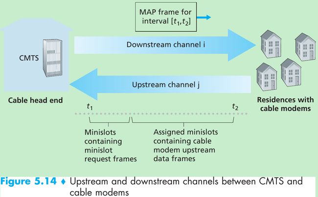
- Figure 5.14: each upstream channel is divided into intervals of time(TDM-like), each containing a sequence of mini-slots during which cable modems can transmit to the CMTS.
- The CMTS grants permission to individual cable modems to transmit during specific mini-slots by sending MAP message on a downstream channel to specify which cable modem can transmit during which mini-slot for the interval of time specified in the control message. Since mini-slots are explicitly allocated to cable modems, the CMTS can ensure there are no colliding transmissions during a mini-slot.
- In order to make the CMTS know which cable modems have data to send, cable modems send mini-slot-request frames to the CMTS during a set of interval mini-slots that are dedicated for this purpose(Figure 5.14). These frames are transmitted in a random access manner, so may collide with each other.
- A cable modem can neither sense whether the upstream channel is busy nor detect collisions. It infers that its mini-slot-request frame experienced a collision if it doesn’t receive a response to the requested allocation in the next downstream control message. When a collision is inferred, it uses binary exponential backoff to defer the retransmission of its mini-slot-request frame to a future time slot.
5.4 Switched Local Area Networks
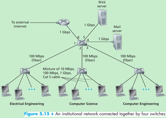
- Figure 5.15 shows a switched local network. These switches operate at the link layer, they switch link-layer frames, don’t recognize network-layer addresses and don’t use routing algorithms.
5.4.1 Link-Layer Addressing and ARP
MAC Addresses
- Hosts and routers have link-layer addresses and network-layer addresses. In truth, it is not hosts and routers that have link-layer addresses but rather their adapters(i.e., network interfaces) that have link-layer addresses. A host or router with multiple network interfaces will have multiple link-layer addresses and multiple IP addresses associated with it.
- Link-layer switches don’t have link-layer addresses associated with their interfaces that connect to hosts and routers because their job is to carry datagrams between hosts and routers and they do this job transparently(i.e., without the host or router having to explicitly address the frame to the intervening switch).
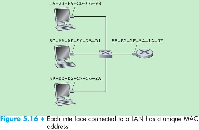
- Figure 5.16. A link-layer address is called a LAN address, a physical address, or a MAC address. For most LANs(including Ethernet and 802.11 wireless LANs), the MAC address is 6 bytes long. The IEEE manages the MAC address space and no two adapters have the same MAC address.
- An adapter’s MAC address has a flat structure and doesn’t change no matter where the adapter goes. IP addresses have a hierarchical structure(i.e., a network part and a host part) and a host’s IP addresses needs to be changed when the host moves.
- When an adapter wants to send a frame, the sending adapter inserts the destination adapter’s MAC address into the frame and then sends the frame into the LAN. A switch occasionally broadcasts an incoming frame onto all of its interfaces, thus, when an adapter receives a frame, it will check to see whether the destination MAC address in the frame matches its own MAC address.
- If match, the adapter extracts the enclosed datagram and passes the datagram up the protocol stack.
- If not match, the adapter discards the frame without passing the datagram up.
- When a sending adapter wants all the other adapters on the LAN to receive and process the frame it is about to send, it inserts a MAC broadcast address into the destination address field of the frame. For LANs that use 6-byte addresses(such as Ethernet and 802.11), the broadcast address is a string of 48 consecutive 1s (FF-FF-FF-FF-FF-FF in hexadecimal notation).
- Reasons for why hosts and router interfaces have MAC addresses in addition to network-layer addresses.
- LANs are designed for arbitrary network-layer protocols, not just for IP and the Internet. If adapters were assigned only IP addresses, then adapters would not be able to support other network-layer protocols.
- If adapters were to use network-layer addresses instead of MAC addresses, the network-layer address would have to be stored in the adapter RAM and reconfigured every time the adapter was moved or powered up.
- Another option is to not use any addresses in the adapters and have each adapter pass the data(typically, IP datagram) of each frame it receives up the protocol stack. The network layer could then check for a matching network-layer address.
Problem: The host would be interrupted by every frame sent on the LAN, including by frames that were destined for other hosts on the same broadcast LAN. - In summary, in order for the layers to be independent building blocks in a network architecture, different layers need to have their own addressing scheme. We have seen three types of addresses: host names for the application layer, IP addresses for the network layer, and MAC addresses for the link layer.
Address Resolution Protocol(ARP)
- Address Resolution Protocol(ARP) [RFC 826]: translate between network-layer addresses(e.g., IP addresses) and link-layer addresses(i.e., MAC addresses).

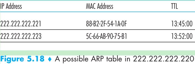
- Figure 5.18. Each host and router has an ARP table in its memory that contains mappings of IP addresses to MAC addresses and a time-to-live(TTL) value(indicates when each mapping will be deleted from the table).
A table doesn’t necessarily contain an entry for every host and router on the subnet; some may have never been entered into the table, and others may have expired. - When source host wants to send a datagram that is IP-addressed to another host or router on that subnet:
- The sending host uses ARP to determine the MAC address for the destination host.
- The source give its adapter the IP datagram and the destination’s MAC address.
- The adapter construct a link-layer frame containing the destination’s MAC address and send the frame into the LAN.
- Step 1 is easy if the sender’s ARP table has an entry for the destination node, otherwise it uses the ARP query packet(ARP query and response packets have the same format).
- The sender passes an ARP query packet to the adapter with an indication that the adapter should send the packet to the MAC broadcast address(FF-FF-FF-FF-FF-FF).
- The adapter encapsulates the ARP packet in a link-layer frame, uses the broadcast address for the frame’s destination address, and transmits the frame into the subnet.
- The frame containing the ARP query is received by all the other adapters on the subnet, and because of the broadcast address, each adapter passes the ARP packet within the frame up to its ARP module.
- Each of these ARP modules checks to see if its IP address matches the destination IP address in the ARP packet. The one with a match sends back to the querying host a response ARP packet with the desired mapping.
- The querying host then update its ARP table and send its IP datagram, encapsulated in a link-layer frame whose destination MAC is that of the host or router responding to the earlier ARP query.
- Difference between ARP and DNS(which resolves host names to IP addresses):
- DNS resolves host names for hosts anywhere in the Internet.
- ARP resolves IP addresses only for hosts and router interfaces on the same subnet.
Points to the ARP protocol
- First, the query ARP message is sent within a broadcast frame, whereas the response ARP message is sent within a standard frame.
- Second, ARP is plug-and-play: an ARP table gets built automatically, it doesn’t have to be configured by a system administrator. If a host becomes disconnected from the subnet, its entry is eventually deleted from the other ARP tables in the subnet.
- Third, an ARP packet is encapsulated within a link-layer frame and thus lies above the link layer, but an ARP packet has fields containing link-layer addresses and thus is a link-layer protocol, but it also contains network-layer addresses and thus is also a network-layer protocol. Conclusion: ARP is considered a protocol that straddles the boundary between the link and network layers: not fitting neatly into the simple layered protocol stack.
Sending a Datagram off the Subnet
- How does a host on a subnet send a network-layer datagram to a host off the subnet (i.e., across a router onto another subnet)?
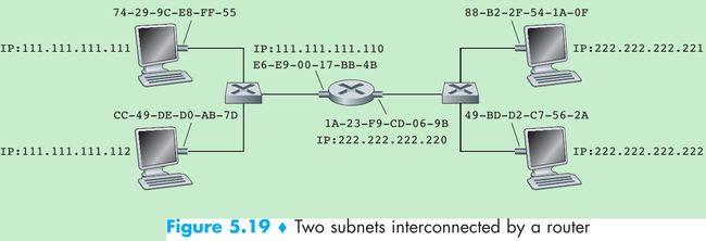
- Figure 5.19. Each host has one IP address and one adapter. A router has an IP address for each of its interfaces, and for each router interface there is an ARP module and an adapter. Each adapter in the network has its own MAC address.
- Subnet 1 has the network address 111.111.111/24 and Subnet 2 has the network address 222.222.222/24. Thus all of the interfaces connected to Subnet 1 have addresses of the form 1*.xxx and all of the interfaces connected to Subnet 2 have addresses of the form 2*.xxx.
- Suppose host 1*.111 wants to send a datagram to a host 2*.222. First, the sending host passes the datagram to its adapter and indicate to its adapter a destination MAC address. What MAC address should the adapter use?
- If the sending adapter were to use host 2*.222’s MAC address, then none of the adapters on Subnet 1 would pass the IP datagram up to its network layer, since the frame’s destination address would not match the MAC address of any adapter on Subnet 1.
- In order for a datagram to go from 1*.111 to a host on Subnet 2, the datagram must first be sent to the router interface 1*.110, which is the IP address of the first-hop router on the path to the final destination. The MAC address for the frame is the address of the adapter for router interface 1*.110(E6-E9-00-17-BB-4B).
- The sending host acquire the MAC address for 1*.110 by using ARP. After the sending adapter has this MAC address, it creates a frame(containing the datagram addressed to 2*.222) and sends the frame into Subnet 1. The router adapter on Subnet 1 sees that the link-layer frame is addressed to it, and passes the frame to the network layer of the router. The IP datagram has successfully been moved from source host to the router.
- The router now determines the interface on which the datagram is to be forwarded by consulting a forwarding table in the router. The forwarding table tells the router that the datagram is to be forwarded via router interface 2*.220. This interface then passes the datagram to its adapter, which encapsulates the datagram in a new frame and sends the frame into Subnet 2.
- This time, the destination MAC address of the frame is the MAC address of the ultimate destination. The router obtain this destination MAC address by ARP.
5.4.2 Ethernet
Ethernet Frame Structure
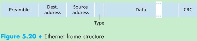
- Figure 5.20. Consider sending an IP datagram from one host to another host with both hosts on the same Ethernet LAN.
- Sending adapter A’s MAC address: AA-AA-AA-AA-AA-AA. The sending adapter encapsulates the IP datagram within an Ethernet frame and passes the frame to the physical layer.
- Receiving adapter B’s MAC address: BB-BB-BB-BB-BB-BB. The receiving adapter receives the frame from the physical layer, extracts the IP datagram, and passes the IP datagram to the network layer.
- Preamble(8 bytes): Each of the first 7 bytes of the preamble has a value of 10101010; the last byte is 10101011. The first 7 bytes of the preamble serve to “wake up” the receiving adapters and to synchronize their clocks to that of the sender’s clock.
- Why should the clocks be out of synchronization?
Since adapter A will not transmit the frame at exactly the target rate(10 Mbps, 100 Mbps, or 1 Gbps depending on the type of Ethernet LAN), there will be some drift that is not known a priori by the other adapters on the LAN. A receiving adapter can lock onto adapter A’s clock by locking onto the bits in the first 7 bytes of the preamble. The last 2 bits(the first two consecutive 1s) alert adapter B that the important stuff is about to come. - Destination address(6 bytes). This field contains the MAC address of the destination adapter, BB-BB-BB-BB-BB-BB. When adapter B receives an Ethernet frame whose destination address is either BB-BB-BB-BB-BB-BB or the MAC broadcast address, it passes the contents of the frame’s data field to the network layer; otherwise, it discards the frame.
- Source address(6 bytes). This field contains the MAC address of the adapter that transmits the frame onto the LAN, in this example, AA-AA-AA-AA-AA-AA.
- Type field(2 bytes). The type field permits Ethernet to multiplex network-layer protocols. When the Ethernet frame arrives at adapter B, adapter B needs to know to which network-layer protocol it should pass(demultiplex) the contents of the data field. IP and other network-layer protocols each have their own type number.
- Data field(46 to 1500 bytes). This field carries the IP datagram.
- The maximum transmission unit(MTU) of Ethernet is 1500 bytes: if the IP datagram exceeds 1500 bytes, then the host has to fragment the datagram.
- The minimum size of the data field is 46 bytes: if the IP datagram is less than 46 bytes, the data field has to be stuffed to fill it out to 46 bytes. When stuffing is used, the data passed to the network layer contains the stuffing and an IP datagram. The network layer uses the length field in the IP datagram header to remove the stuffing.
- Cyclic redundancy check(CRC, 4 bytes). The purpose of the CRC field is to allow the receiving adapter B to detect bit errors in the frame.
- Ethernet provides connectionless service to the network layer: when adapter A wants to send a datagram to adapter B, adapter A encapsulates the datagram in an Ethernet frame and sends the frame into the LAN, without first handshaking with adapter B.
- Ethernet provide an unreliable service to the network layer: when adapter B receives a frame from adapter A, it runs the frame through a CRC check, but doesn’t sends an ack/negative-ack when a frame passes/fails the CRC check. When a frame fails the CRC check, adapter B discards the frame. Thus, adapter A has no idea whether its transmitted frame reached adapter B and passed the CRC check. This means that the stream of datagrams passed to the network layer can have gaps.
- If there are gaps due to discarded Ethernet frames, does the application at Host B see gaps?
- For the application using UDP: it will see gaps in the data.
- For TCP: TCP in Host B will not acknowledge the data contained in discarded frames, causing TCP in Host A to retransmit.
Ethernet Technologies
- Ethernet comes in many different flavors, with acronyms such as 10BASE-T, 10BASE-2, 100BASE-T, 1000BASE-LX, and 10GBASE-T. These and many other Ethernet technologies have been standardized by the IEEE 802.3 CSMA/CD (Ethernet) working group.
-
- The first part of the acronym refers to the speed of the standard: 10 Megabit/s, 100 Megabit, Gigabit, and 10 Gigabit Ethernet, respectively.
- “BASE” refers to baseband Ethernet, meaning that the physical media only carries Ethernet traffic.
- The final part refers to the physical media itself. Ethernet is both a link-layer and a physical-layer specification and is carried over a variety of physical media.
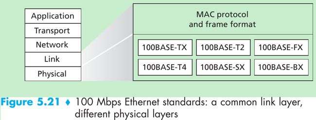
- Figure 5.21 shows different standards and the common Ethernet MAC protocol and frame format.
- Gigabit Ethernet offers a raw data rate of 1,000 Mbps and maintains full compatibility with the installed base of Ethernet equipment. The standard for Gigabit Ethernet(IEEE 802.3z) does the following:
• Uses the standard Ethernet frame format(Figure 5.20) and is backward compatible with 10BASE-T and 100BASE-T technologies.
• Allows for point-to-point links as well as shared broadcast channels. Point-to-point links use switches while broadcast channels use hubs. In Gigabit Ethernet jargon, hubs are called buffered distributors.
• Uses CSMA/CD for shared broadcast channels. In order to have efficiency, the maximum distance between nodes must be severely restricted.
• Allows for full-duplex operation at 1,000 Mbps in both directions for point-to-point channels. - In the days of bus topologies and hub-based star topologies, Ethernet was a broadcast link(defined in Section 5.3) in which frame collisions occurred when nodes transmitted at the same time. To deal with these collisions, the Ethernet standard included the CSMA/CD protocol. But if the use of Ethernet today is a switch-based star topology, using store-and-forward packet switching, is there need for an Ethernet MAC protocol?
- A switch coordinates its transmissions and never forwards more than one frame onto the same interface at any time. Modern switches are full-duplex, so that a switch and a node can each send frames to each other at the same time without interference. In other words, in a switch-based Ethernet LAN there are no collisions and there is no need for a MAC protocol.
5.4.3 Link-Layer Switches
- The role of the switch is to receive incoming link-layer frames and forward them onto outgoing links.
- The switch itself is transparent to the hosts and routers in the subnet: a host/router addresses a frame to another host/router(not to the switch) and sends the frame into the LAN, unaware that a switch will be receiving the frame and forwarding it.
- Since the rate at which frames arrive to any one of the switch’s output interfaces may exceed the link capacity of that interface, switch output interfaces have buffers.
Filtering and Forwarding
- Filtering: determines whether a frame should be forwarded to some interface or should be dropped.
Forwarding: determines the interfaces to which a frame should be directed, and then moves the frame to those interfaces. - Switch filtering and forwarding are done with a switch table that contains entries for some, but not necessarily all, of the hosts and routers on a LAN. An entry in the switch table contains
(1) a MAC address,
(2) the switch interface that leads toward that MAC address,
(3) the time at which the entry was placed in the table.
Figure 5.22.
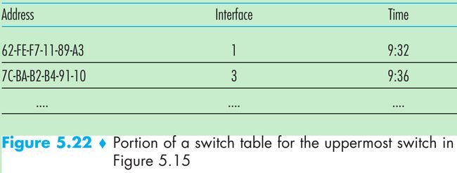
- Suppose a frame with destination address DD-DD-DD-DD-DD-DD arrives at the switch on interface x. The switch indexes its table with the MAC address DD-DD-DD-DD-DD-DD. There are three possible cases:
- There is no entry in the table for DD-DD-DD-DD-DD-DD. The switch forwards copies of the frame to the output buffers preceding all interfaces except for interface x, that is, the switch broadcasts the frame.
- There is an entry in the table associating DD-DD-DD-DD-DD-DD with interface x. The frame is coming from a LAN segment that contains adapter DD-DD-DD-DD-DD-DD. There is no need to forward the frame to any of the other interfaces, the switch performs the filtering function by discarding the frame.
- There is an entry in the table associating DD-DD-DD-DD-DD-DD with interface y. The frame needs to be forwarded to the LAN segment attached to interface y. The switch performs its forwarding function by putting the frame in an output buffer that precedes interface y.
Self-Learning
- Switches are self-learning: switch table is built automatically, dynamically, and autonomously without any intervention from a network administrator or from a configuration protocol. This capability is accomplished as follows:
- The switch table is initially empty.
- For each incoming frame received on an interface, the switch stores in its table
(1) the MAC address in the frame’s source address field,
(2) the interface from which the frame arrived, and
(3) the current time.
So the switch records in its table the LAN segment on which the sender resides. If every host in the LAN sends a frame, then every host will get recorded in the table. - The switch deletes an address in the table if no frames are received with that address as the source address after the aging time. If a PC is replaced by another PC with a different adapter, the MAC address of the original PC will eventually be purged from the switch table.
- Switches are plug-and-play devices because they require no intervention from a network administrator or user. A network administrator wanting to install a switch only need connect the LAN segments to the switch interfaces. Switches are also full-duplex, meaning any switch interface can send and receive at the same time.
Properties of Link-Layer Switching
- Advantages of switches, not broadcast links such as buses or hub-based star topologies:
- Elimination of collisions.
In a LAN built from switches and without hubs, there is no wasted bandwidth due to collisions. The switches buffer frames and never transmit more than one frame on a segment at any one time. As with a router, the maximum aggregate throughput of a switch is the sum of all the switch interface rates. Thus, switches provide a performance improvement over LANs with broadcast links. - Heterogeneous links.
Because a switch isolates one link from another, the different links in the LAN can operate at different speeds and can run over different media. Thus, a switch is ideal for mixing legacy equipment with new equipment. - Management.
For example, if an adapter malfunctions and continually sends Ethernet frames(called a jabbering adapter), a switch can detect the problem and internally disconnect the malfunctioning adapter.
Switches Versus Routers
- Routers are store-and-forward packet switches that forward packets using network-layer addresses; switch is a store-and-forward packet switch but it forwards packets using MAC addresses. Router is a layer-3 packet switch, switch is a layer-2 packet switch.
- Given that both switches and routers are candidates for interconnection devices, what are the pros and cons of the two approaches?
- Pros of switches:
- Switches are plug-and-play.
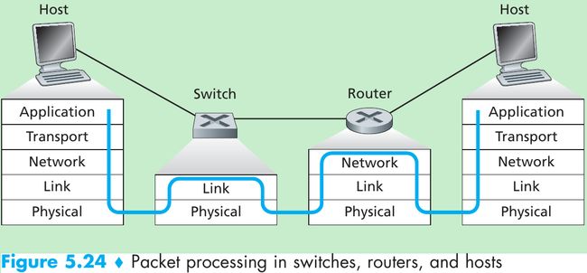
- Switches have relatively high filtering and forwarding rates(Figure 5.24) since switches process frames only up through layer 2, whereas routers have to process datagrams up through layer 3.
- Cons of switches:
- To prevent the cycling of broadcast frames, the active topology of a switched network is restricted to a spanning tree.
- A large switched network would require large ARP tables in the hosts and routers and would generate substantial ARP traffic and processing.
- Switches are susceptible to broadcast storms: if one host goes haywire and transmits an endless stream of Ethernet broadcast frames, the switches will forward all of these frames, causing the entire network to collapse.
- Pros of routers:
- Because network addressing is hierarchical(not flat as MAC addressing), packets don’t normally cycle through routers even when the network has redundant paths. Thus, packets are not restricted to a spanning tree and can use the best path between source and destination.
- Because routers don’t have the spanning tree restriction, they have allowed the Internet to be built with a rich topology that includes, e.g., multiple active links between Europe and North America.
- Routers provide firewall protection against layer-2 broadcast storms.
- Cons of routers:
- Routers are not plug-and-play: they and the hosts that connect to them need their IP addresses to be configured.
- Routers often have a larger per-packet processing time than switches because they have to process up through the layer-3 fields.
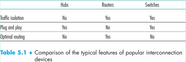
- Table 5.1.
- Switches suffice for small networks that consists of a few hundred hosts since they localize traffic and increase aggregate throughput without requiring any configuration of IP addresses.
- Larger networks consisting of thousands of hosts typically include routers within the network(in addition to switches). The routers provide a robust isolation of traffic, control broadcast storms, and use more optimal routes among the hosts in the network.
5.4.4 Virtual Local Area Networks(VLANs)
- Figure 5.15: modern institutional LANs are often configured hierarchically, with each department having its own switched LAN connected to the switched LANs of other groups via a switch hierarchy. Three drawbacks in this kind of configuration:
- Lack of traffic isolation.
-1- Though the hierarchy localizes group traffic to within a single switch, broadcast traffic(e.g., frames carrying ARP and DHCP messages or frames whose destination has not yet been learned by a self-learning switch) must traverse the entire institutional network. Limiting the scope of such broadcast traffic would improve LAN performance.
-2- It is desirable to limit LAN broadcast traffic for security/privacy reasons. For example, if one group contains the company’s executive management team and another group contains disgruntled employees running Wireshark packet sniffers, the network manager may prefer that the executives’ traffic never reaches employee hosts. This type of isolation could be provided by replacing the center switch in Figure 5.15 with a router. This isolation also can be achieved via a switched(layer 2) solution. - Inefficient use of switches. If the institution had 10 groups, then 10 first-level switches would be required. If each group were small, then a single 96-port switch would be large enough to accommodate everyone, but this single switch would not provide traffic isolation.
- Managing users. If an employee moves between groups, the physical cabling must be changed to connect the employee to a different switch in Figure 5.15. Employees belonging to two groups make the problem harder.
- Lack of traffic isolation.
- A switch that supports VLANs allows multiple virtual local area networks to be defined over a single physical local area network infrastructure. Hosts within a VLAN communicate with each other as if they were connected to the switch.
- In a port-based VLAN, the switch’s ports(interfaces) are divided into groups by the network manager. Each group constitutes a VLAN, with the ports in each VLAN forming a broadcast domain(i.e., broadcast traffic from one port can only reach other ports in the group).
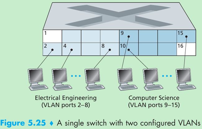
- Figure 5.25 shows a single switch with 16 ports. Ports 2 to 8 belong to the EE VLAN, while ports 9 to 15 belong to the CS VLAN(ports 1 and 16 are unassigned).
- This VLAN solves all of the difficulties noted above: EE and CS VLAN frames are isolated from each other, the two switches in Figure 5.15 have been replaced by a single switch, and if the user at switch port 8 joins the CS Department, the network operator simply reconfigures the VLAN software so that port 8 is now associated with the CS VLAN.
- How the VLAN switch is configured and operates: the network manager declares a port to belong to a given VLAN using switch management software, a table of port-to-VLAN mappings is maintained within the switch; and switch hardware only delivers frames between ports belonging to the same VLAN.
- But by isolating the two VLANs, how can traffic from the EE Department be sent to the CS Department?
- One way is to connect a VLAN switch port(e.g., port 1 in Figure 5.25) to an external router and configure that port to belong both the EE and CS VLANs. In this case, even though the EE and CS departments share the same physical switch, the logical configuration would look as if the EE and CS departments had separate switches connected via a router. An IP datagram going from the EE to the CS department would first cross the EE VLAN to reach the router and then be forwarded by the router back over the CS VLAN to the CS host.
- Return to Figure 5.15, suppose that rather than having a separate Computer Engineering department, some EE and CS faculty are housed in a separate building, where they need network access, and they’d like to be part of their department’s VLAN.
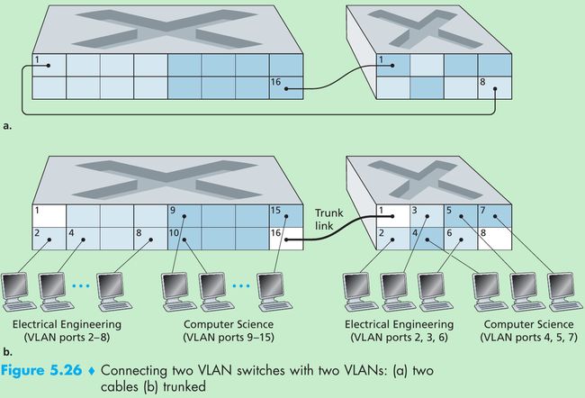
- Figure 5.26 shows a second 8-port switch, where the switch ports have been defined as belonging to the EE or the CS VLAN, as needed. How should these two switches be inter-connected? One solution is to define a port belonging to the CS VLAN on each switch(similarly for the EE VLAN) and to connect these ports to each other, as shown in Figure 5.26(a). This solution doesn’t scale since N VLANS would require N ports on each switch simply to interconnect the two switches.
- A more scalable approach is known as VLAN trunking. In Figure 5.26(b), a special port on each switch(port 16 on the left switch and port 1 on the right switch) is configured as a trunk port to interconnect the two VLAN switches. The trunk port belongs to all VLANs, and frames sent to any VLAN are forwarded over the trunk link to the other switch. How does a switch know that a frame arriving on a trunk port belongs to a particular VLAN? The IEEE has defined an extended Ethernet frame format, 802.1Q, for frames crossing a VLAN trunk.

- Figure 5.27, the 802.1Q frame consists of the standard Ethernet frame with a four-byte VLAN tag added into the header that carries the identity of the VLAN to which the frame belongs. The VLAN tag is added into a frame by the switch at the sending side of a VLAN trunk, parsed, and removed by the switch at the receiving side of the trunk.
- The VLAN tag itself consists of a 2-byte Tag Protocol Identifier(TPID) field(with a fixed hexadecimal value of 81-00), a 2-byte Tag Control Information field that contains a 12-bit VLAN identifier field, and a 3-bit priority field that is similar in intent to the IP datagram TOS field.
5.5 Link Virtualization: A Network as a Link Layer(No need)
5.6 Data Center Networking
- Each data center has its own data center network that interconnects its hosts with each other and interconnects the data center with the Internet.
- The worker bees in a data center are the hosts: they serve content(e.g., Web pages and videos), store emails and documents, and collectively perform massively distributed computations(e.g., distributed index computations for search engines).
- The hosts in data centers, called blades and resembling pizza boxes, are generally commodity hosts that include CPU, memory, and disk storage. The hosts are stacked in racks, with each rack typically having 20 to 40 blades. At the top of each rack there is a switch, aptly named the Top of Rack(TOR) switch, that interconnects the hosts in the rack with each other and with other switches in the data center.
- Specifically, each host in the rack has a network interface card that connects to its TOR switch, and each TOR switch has additional ports that can be connected to other switches. Each host is also assigned its own data-center-internal IP address.
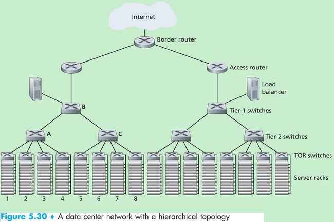
- The data center network supports two types of traffic: traffic flowing between external clients and internal hosts and traffic flowing between internal hosts. To handle flows between external clients and internal hosts, the data center network includes one or more border routers, connecting the data center network to the public Internet. The data center network therefore interconnects the racks with each other and connects the racks to the border routers. Figure 5.30 shows an example of a data center network.
Load Balancing
- A cloud data center provides many applications concurrently, such as search, email, and video applications.
- To support requests from external clients, each application is associated with a publicly visible IP address to which clients send their requests and from which they receive responses.
- Inside the data center, the external requests are first directed to a load balancer whose job it is to distribute requests to the hosts, balancing the load across the hosts as a function of their current load.
- A large data center often have several Internet load balancers, each one devoted to a set of specific cloud applications. Such a load balancer is sometimes referred to as a “layer-4 switch” since it makes decisions based on the destination port number(layer 4) and destination IP address in the packet.
- Upon receiving a request for a particular application, the load balancer forwards it to one of the hosts that handles the application.(A host may then invoke the services of other hosts to help process the request.) When the host finishes processing the request, it sends its response back to the load balancer, which in turn relays the response back to the external client.
- The load balancer not only balances the work load across hosts, but also provides a NAT-like function, translating the public external IP address to the internal IP address of the appropriate host, and then translating back for packets traveling in the reverse direction back to the clients.
Hierarchical Architecture
- To scale to tens to hundreds of thousands of hosts, a data center often employs a hierarchy of routers and switches, such as the topology shown in Figure 5.30. At the top of the hierarchy, the border router connects to access routers. Below each access router there are three tiers of switches.
- Each access router connects to a top-tier switch, and each top-tier switch connects to multiple second-tier switches and a load balancer. Each second-tier switch in turn connects to multiple racks via the racks’ TOR switches(third-tier switches). All links typically use Ethernet for their link-layer and physical-layer protocols, with a mix of copper and fiber cabling.
- Because it is critical for a cloud application provider to continually provide applications with high availability, data centers also include redundant network equipment and redundant links in their designs(not shown in Figure 5.30).
- For example, each TOR switch can connect to two tier-2 switches, and each access router, tier-1 switch, and tier-2 switch can be duplicated and integrated into the design. In the hierarchical design in Figure 5.30, observe that the hosts below each access router form a single subnet. In order to localize ARP broadcast traffic, each of these subnets is further partitioned into smaller VLAN subnets, each comprising a few hundred hosts.
- Although the hierarchical architecture solves the problem of scale, it suffers from limited host-to-host capacity. Consider Figure 5.30, and suppose each host connects to its TOR switch with a 1 Gbps link, whereas the links between switches are 10 Gbps Ethernet links. Two hosts in the same rack can always communicate at a full 1 Gbps, limited only by the rate of the hosts’ network interface cards. However, if there are many simultaneous flows in the data center network, the maximum rate between two hosts in different racks can be much less.
- To gain insight into this issue, consider a traffic pattern consisting of 40 simultaneous flows between 40 pairs of hosts in different racks. Suppose each of 10 hosts in rack 1 in Figure 5.30 sends a flow to a corresponding host in rack 5. Similarly, there are ten simultaneous flows between pairs of hosts in racks 2 and 6, ten simultaneous flows between racks 3 and 7, and ten simultaneous flows between racks 4 and 8. If each flow evenly shares a link’s capacity with other flows traversing that link, then the 40 flows crossing the 10 Gbps A-to-B link(as well as the 10 Gbps B-to-C link) will each only receive 10 Gbps / 40 = 250 Mbps, which is significantly less than the 1 Gbps network interface card rate.
- One solution is to deploy higher-rate switches and routers. But this would significantly increase the cost of the data center,.
Trends in Data Center Networking
- One trend is to deploy new interconnection architectures and network protocols that overcome the drawbacks of the traditional hierarchical designs. One such approach is to replace the hierarchy of switches and routers with a fully connected topology, such as the topology shown in Figure 5.31.
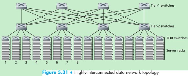
- In this design, each tier-1 switch connects to all of the tier-2 switches so that
(1) host-to-host traffic never has to rise above the switch tiers, and
(2) with n tier-1 switches, between any two tier-2 switches there are n disjoint paths. Such a design can significantly improve the host-to-host capacity. - To see this, consider again our example of 40 flows. The topology in Figure 5.31 can handle such a flow pattern since there are four distinct paths between the first tier-2 switch and the second tier-2 switch, together providing an aggregate capacity of 40 Gbps between the first two tier-2 switches.
- Such a design not only alleviates the host-to-host capacity limitation, but also creates a more flexible computation and service environment in which communication between any two racks not connected to the same switch is logically equivalent, irrespective of their locations in the data center.
5.7 Retrospective: A Day in the Life of a Web Page Request
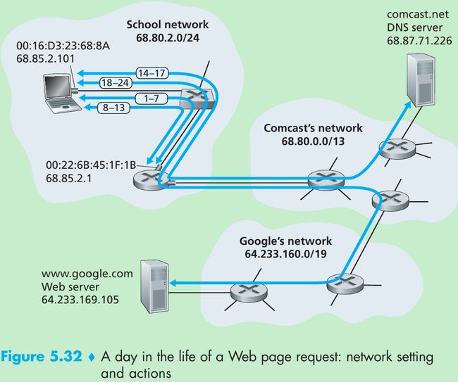
- Figure 5.32 illustrates our setting: a student, Bob, connects a laptop to his school’s Ethernet switch and downloads a web page(say www.google.com).
5.7.1 Getting Started: DHCP, UDP, IP, and Ethernet
- Suppose that Bob boots up his laptop and then connects it to an Ethernet cable connected to the school’s Ethernet switch, which in turn is connected to the school’s router. The school’s router is connected to an ISP comcast.net that is providing the DNS service request for the school; thus, the DNS server resides in the Comcast network rather than the school network. We assume that the DHCP server is running within the router, as is often the case.
- When Bob first connects his laptop to the network, he can’t do anything without an IP address. The first network-related action taken by Bob’s laptop is to run the DHCP protocol to obtain an IP address, as well as other information, from the local DHCP server:
- The operating system on Bob’s laptop creates a DHCP request message(Section 4.4.2) and puts this message within a UDP segment(Section 3.3) with destination port 67 (DHCP server) and source port 68(DHCP client). The UDP segment is then placed within an IP datagram(Section 4.4.1) with a broadcast IP destination address (255.255.255.255) and a source IP address of 0.0.0.0, since Bob’s laptop doesn’t yet have an IP address.
- The IP datagram containing the DHCP request message is then placed within an Ethernet frame(Section 5.4.2). The Ethernet frame has a destination MAC addresses of FF:FF:FF:FF:FF:FF so that the frame will be broadcast to all devices connected to the switch; the frame’s source MAC address is that of Bob’s laptop, 00:16:D3:23:68:8A.
- The broadcast Ethernet frame containing the DHCP request is the first frame sent by Bob’s laptop to the Ethernet switch. The switch broadcasts the incoming frame on all outgoing ports, including the port connected to the router.
- The router receives the broadcast Ethernet frame containing the DHCP request on its interface with MAC address 00:22:6B:45:1F:1B and the IP datagram is extracted from the Ethernet frame. The datagram’s broadcast IP destination address indicates that this IP datagram should be processed by upper layer protocols at this node, so the datagram’s payload(a UDP segment) is thus demultiplexed(Section 3.2) up to UDP, and the DHCP request message is extracted from the UDP segment. The DHCP server now has the DHCP request message.
- Suppose the DHCP server running within the router can allocate IP addresses in the CIDR(Section 4.4.2) block 68.85.2.0/24. In this example, all IP addresses used within the school are thus within Comcast’s address block. Suppose the DHCP server allocates address 68.85.2.101 to Bob’s laptop. The DHCP server creates a DHCP ACK message(Section 4.4.2) containing this IP address, as well as the IP address of the DNS server(68.87.71.226), the IP address for the default gateway router (68.85.2.1), and the subnet block(68.85.2.0/24)(i.e., the “network mask”). The DHCP message is put inside a UDP segment, which is put inside an IP datagram, which is put inside an Ethernet frame. The Ethernet frame has a source MAC address of the router’s interface to the home network(00:22:6B:45:1F:1B) and a destination MAC address of Bob’s laptop(00:16:D3:23:68:8A).
- The Ethernet frame containing the DHCP ACK is sent(unicast) by the router to the switch. Because the switch is self-learning(Section 5.4.3) and previously received an Ethernet frame(containing the DHCP request) from Bob’s laptop, the switch knows to forward a frame addressed to 00:16:D3:23:68:8A only to the output port leading to Bob’s laptop.
- Bob’s laptop receives the Ethernet frame containing the DHCP ACK, extracts the IP datagram from the Ethernet frame, extracts the UDP segment from the IP datagram, and extracts the DHCP ACK message from the UDP segment. Bob’s DHCP client then records its IP address and the IP address of its DNS server. It also installs the address of the default gateway into its IP forwarding table(Section 4.1). Bob’s laptop will send all datagrams with destination address outside of its subnet 68.85.2.0/24 to the default gateway. At this point, Bob’s laptop has initialized its networking components and is ready to begin processing the Web page fetch.(Note that only the last two DHCP steps of the four presented in Chapter 4 are actually necessary.)
5.7.2 Still Getting Started: DNS and ARP
- When Bob types the URL for www.google.com into his Web browser, Bob’s Web browser begins the process by creating a TCP socket(Section 2.7) that will be used to send the HTTP request(Section 2.2) to www.google.com. In order to create the socket, Bob’s laptop will need to know the IP address of www.google.com. Section 2.5: the DNS protocol is used to provide this name-to-IP-address translation service.
- The operating system on Bob’s laptop thus creates a DNS query message(Section 2.5.3), putting the string “www.google.com” in the question section of the DNS message. This DNS message is then placed within a UDP segment with a destination port of 53(DNS server). The UDP segment is then placed within an IP datagram with an IP destination address of 68.87.71.226(the address of the DNS server returned in the DHCP ACK in step 5) and a source IP address of 68.85.2.101.
- Bob’s laptop then places the datagram containing the DNS query message in an Ethernet frame. This frame will be sent(addressed, at the link layer) to the gateway router in Bob’s school’s network. However, even though Bob’s laptop knows the IP address of the school’s gateway router(68.85.2.1) via the DHCP ACK message in step 5 above, it doesn’t know the gateway router’s MAC address. In order to obtain the MAC address of the gateway router, Bob’s lap-top will need to use the ARP protocol(Section 5.4.1).
- Bob’s laptop creates an ARP query message with a target IP address of 68.85.2.1(the default gateway), places the ARP message within an Ethernet frame with a broadcast destination address(FF:FF:FF:FF:FF:FF) and sends the Ethernet frame to the switch, which delivers the frame to all connected devices, including the gateway router.
- The gateway router receives the frame containing the ARP query message on the interface to the school network, and finds that the target IP address of 68.85.2.1 in the ARP message matches the IP address of its interface. The gateway router thus prepares an ARP reply, indicating that its MAC address of 00:22:6B:45:1F:1B corresponds to IP address 68.85.2.1. It places the ARP reply message in an Ethernet frame, with a destination address of 00:16:D3:23:68:8A(Bob’s laptop) and sends the frame to the switch, which delivers the frame to Bob’s laptop.
- Bob’s laptop receives the frame containing the ARP reply message and extracts the MAC address of the gateway router(00:22:6B:45:1F:1B) from the ARP reply message.
- Bob’s laptop can now address the Ethernet frame containing the DNS query to the gateway router’s MAC address. Note that the IP datagram in this frame has an IP destination address of 68.87.71.226(the DNS server), while the frame has a destination address of 00:22:6B:45:1F:1B(the gateway router). Bob’s laptop sends this frame to the switch, which delivers the frame to the gateway router.
5.7.3 Still Getting Started: Intra-Domain Routing to the DNS Server
- The gateway router receives the frame and extracts the IP datagram containing the DNS query. The router looks up the destination address of this datagram (68.87.71.226) and determines from its forwarding table that the datagram should be sent to the leftmost router in the Comcast network in Figure 5.32. The IP datagram is placed inside a link-layer frame appropriate for the link connecting the school’s router to the leftmost Comcast router and the frame is sent over this link.
- The leftmost router in the Comcast network receives the frame, extracts the IP datagram, examines the datagram’s destination address(68.87.71.226) and determines the outgoing interface on which to forward the datagram towards the DNS server from its forwarding table, which has been filled in by Comcast’s intra-domain protocol(such as RIP in Section 4.6) and the Internet’s inter-domain protocol, BGP.
- Eventually the IP datagram containing the DNS query arrives at the DNS server. The DNS server extracts the DNS query message, looks up the name www.google.com in its DNS database(Section 2.5), and finds the DNS resource record that contains the IP address(64.233.169.105) for www.google.com.(Assuming that it is currently cached in the DNS server, this cached data originated in the authoritative DNS server(Section 2.5.2) for google.com.) The DNS server forms a DNS reply message containing this hostname-to-IP-address mapping, and places the DNS reply message in a UDP segment, and the segment within an IP datagram addressed to Bob’s laptop (68.85.2.101). This datagram will be forwarded back through the Comcast network to the school’s router and from there, via the Ethernet switch to Bob’s laptop.
- Bob’s laptop extracts the IP address of the server www.google.com from the DNS message.
5.7.4 Web Client-Server Interaction: TCP and HTTP
- Now that Bob’s laptop has the IP address of www.google.com, it can create the TCP socket(Section 2.7) that will be used to send the HTTP GET message(Section 2.2.3) to www.google.com. When Bob creates the TCP socket, the TCP in Bob’s laptop must first perform a three-way handshake(Section 3.5.6) with the TCP in www.google.com. Bob’s laptop thus first creates a TCP SYN segment with destination port 80(for HTTP), places the TCP segment inside an IP datagram with a destination IP address of 64.233.169.105(www.google.com), places the datagram inside a frame with a destination MAC address of 00:22:6B:45:1F:1B(the gateway router) and sends the frame to the switch.
- The routers in the school network, Comcast’s network, and Google’s network forward the datagram containing the TCP SYN towards www.google.com, using the forwarding table in each router, as in steps 14-16 above. Recall that the router forwarding table entries governing forwarding of packets over the inter-domain link between the Comcast and Google networks are determined by the BGP protocol (Section 4.6.3).
- Eventually, the datagram containing the TCP SYN arrives at www.google.com. The TCP SYN message is extracted from the datagram and demultiplexed to the welcome socket associated with port 80. A connection socket(Section 2.7) is created for the TCP connection between the Google HTTP server and Bob’s laptop. A TCP SYNACK(Section 3.5.6) segment is generated, placed inside a datagram addressed to Bob’s laptop, and finally placed inside a link-layer frame appropriate for the link connecting www.google.com to its first-hop router.
- The datagram containing the TCP SYNACK segment is forwarded through the Google, Comcast, and school networks, eventually arriving at the Ethernet card in Bob’s laptop. The datagram is demultiplexed within the operating system to the TCP socket created in step 18, which enters the connected state.
- With the socket on Bob’s laptop now ready to send bytes to www.google .com, Bob’s browser creates the HTTP GET message(Section 2.2.3) containing the URL to be fetched. The HTTP GET message is then written into the socket, with the GET message becoming the payload of a TCP segment. The TCP segment is placed in a datagram and sent and delivered to www.google.com as in steps 18-20 above.
- The HTTP server at www.google.com reads the HTTP GET message from the TCP socket, creates an HTTP response message(Section 2.2), places the requested Web page content in the body of the HTTP response message, and sends the message into the TCP socket.
- The datagram containing the HTTP reply message is forwarded through the Google, Comcast, and school networks, and arrives at Bob’s laptop. Bob’s Web browser program reads the HTTP response from the socket, extracts the html for the Web page from the body of the HTTP response, and finally displays the Web page!
- We’ve omitted a number of possible additional protocols(e.g., NAT running in the school’s gateway router), and considerations(Web caching, the DNS hierarchy) that one would encounter in the public Internet.
5.8 Summary
Please indicate the source: http://blog.csdn.net/gaoxiangnumber1
Welcome to my github: https://github.com/gaoxiangnumber1