OSPF LSA Type
OSPF LSA Type
https://learningnetwork.cisco.com/blogs/vip-perspectives/2017/11/08/ospf-graphs-lsas-and-the-lsdb
https://networklessons.com/ospf/ospf-lsa-types-explained
1. OSPF uses a 32-bit number as the Node Identifier in the LSDB, called the router ID (RID). By default, OSPF chooses the highest IP address on an up loopback interface first and then the highest IP address on any up interface second as its RID. The RID can also be statically defined with the router-id command in OSPF configuration mode.
2. There is a distinction between an “interface” and a “link”. An interface describes a physical or logical interface on the router (i.e. loopback interfaces, ethernet ports). A link describes a relationship on the graph between two nodes.
Type-1 Router LSAs
This LSA describes a router node itself and all of its relationships or link adjacencies to other nodes. It is originated by every router in the topology and flooded to all routers in a single area. OSPF identifies four types of link adjacencies using Type-1 Router LSAs:
| Link Type | Description | Link ID |
| 1 | Point-to-point connection to another router. | Neighbor router ID |
| 2 | Connection to transit network. | IP address of DR |
| 3 | Connection to stub network. | IP address of the network |
| 4 | Virtual Link | Neighbor router ID |
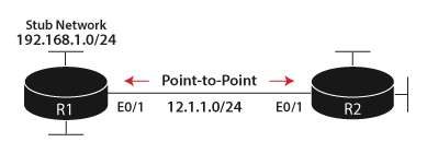
R1 has three links in this network: one to R2 , one to another network segment, and one on the network segment 192.168.1.0/24.
Type-1 Describing Stub Networks
R1 is the only router on the network segment 192.168.1.0/24 in the above topology. Such links are classified as stub networks by OSPF because the segment does not include another OSPF router. (Basically A stub network is a network that contains only a single router - its gateway to the rest of the topology. Typically, all Ethernet interfaces where only end stations are connected are considered as stub networks by OSPF. )
Note that, out of all of the link adjacencies described by a Type-1 Router LSA, the stub network link description is the only one that carries network layer addressing information.
R1#show ip ospf database router self-originate

          OSPF Router with ID (1.1.1.1) (Process ID 1)

              Router Link States (Area 0)

LS age: 835

Options: (No TOS-capability, DC)

LS Type: Router Links

Link State ID: 1.1.1.1

Advertising Router: 1.1.1.1


  Link connected to: a Stub Network

    (Link ID) Network/subnet number: 192.168.1.0

    (Link Data) Network Mask: 255.255.255.0

    Number of MTID metrics: 0

        TOS 0 Metrics: 1
Type-1 Describing Point-to-Point Links
In OSPF, a point-to-point link adjacency is a link that connects to only one other OSPF router.
Link connected to: another Router (point-to-point)

    (Link ID) Neighboring Router ID: 2.2.2.2

    (Link Data) Router Interface address: 12.1.1.1

    Number of MTID metrics: 0

        TOS 0 Metrics: 10

  Link connected to: a Stub Network

  (Link ID) Network/subnet number: 12.1.1.0

    (Link Data) Network Mask: 255.255.255.0

    Number of MTID metrics: 0

        TOS 0 Metrics: 1
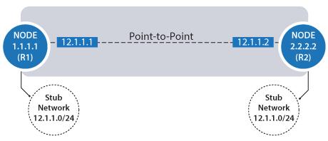
Important! Note that, a P2P link is described by two entries in the LSA1 - one describing the physical interconnection (the direct point-to-point link) referencing Router IDs, the stub network entry indicated by both routers declares the presence of the relevant IP subnet on that link.
- When calculating the path between Nodes 1.1.1.1. and 2.2.2.2, OSPF uses the point-to-point link description.
- When calculating the path to the 12.1.1.0/24 network, OSPF uses the stub network link description.
Type-2 Network LSAs
Multiaccess networks allow multiple devices (at least 2) to connect to the same network segment.
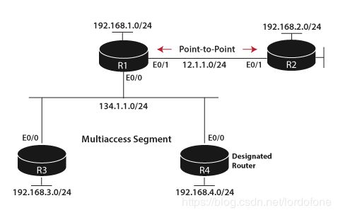
In the topology above can be viewed as:
“Node 1.1.1.1 is connected to Node 3.3.3.3 and Node 4.4.4.4. Node 3.3.3.3 is connected to Node 1.1.1.1 and Node 4.4.4.4. Node 4.4.4.4 is connected to Node 1.1.1.1 and Node 3.3.3.3.” But, this will waste a lot of space in LSDB. That's why we use topology:
“Nodes 1.1.1.1, 3.3.3.3, and 4.4.4.4 are all connected to Transit Network Node 134.1.1.4.”
One router from the segment (the one with higest RID), called the Designated Router. 134.1.1.4 is the interface IP address of DR
R1# show ip ospf database network

--- omitted ---

Options: (No TOS-capability, DC)

LS Type: Network Links

Link State ID: 134.1.1.4 (address of Designated Router)

Advertising Router: 4.4.4.4

LS Seq Number: 80000001

Checksum: 0x9CDC

Length: 36

Network Mask: /24

    Attached Router: 4.4.4.4

      Attached Router: 1.1.1.1

      Attached Router: 3.3.3.3
Type-1 Describing Transit Network
A different view of transit network 134.1.1.4 from LSA-1. Note that LSA-1 doesn't include information like: which routers connect to this multiaccess network; network layer information (like mask), etc.
R1# show ip ospf database router self-originate

--- omitted ---

Options: (No TOS-capability, DC)

LS Type: Router Links

Link State ID: 1.1.1.1

Advertising Router: 1.1.1.1

--- omitted ---

  Link connected to: a Transit Network

    (Link ID) Designated Router address: 134.1.1.4

    (Link Data) Router Interface address: 134.1.1.1

    Number of MTID metrics: 0

      TOS 0 Metrics: 10
Type-3 Summary LSAs
OSPF divide AS into areas merely to reduce the work of SPF. If AS only has one area, the topology will be too big to do SPF efficiently.
Instead of describing the details of what nodes exist in an area and how they are interconnected, Type-3 Summary LSAs only advertise prefixes. In a multi-area OSPF domain, there exists two different kinds of prefixes:
- intra-area: prefixes from within a single area
- inter-area: prefixes from outside a single area
ABR floods Type-3 Summary LSA as follows:
- Type-3 LSAs are generated for intra-area and inter-area prefixes from the backbone area and flooded to non-backbone areas.
- Type-3 LSAs are generated only for intra-area prefixes in non-backbone areas and flooded into the backbone area.
- An ABR only uses Type-3 LSAs from the Backbone area in the SPF calculation
Important! As mentioned before, LSA-1 is within area. But R2 has separate Type-1 Router LSAs for the backbone area and Area 256, as showed below. Because it's an ABR at the boundary of both areas.
R2#show ip ospf database

          OSPF Router with ID (2.2.2.2) (Process ID 1)

              Router Link States (Area 0)

Link ID        ADV Router      Age        Seq#      Checksum Link count

1.1.1.1        1.1.1.1        1576        0x80000004 0x0035FF 4

2.2.2.2        2.2.2.2        1329        0x80000003 0x006C6F 2

3.3.3.3        3.3.3.3        1359        0x80000003 0x009A5C 1

4.4.4.4        4.4.4.4        1255        0x80000004 0x00608A 1

            --- some output has been omitted ---

            Router Link States (Area 256)

Link ID        ADV Router      Age        Seq#      Checksum Link count

2.2.2.2        2.2.2.2        1319        0x80000002 0x007E34 2

5.5.5.5        5.5.5.5        1195        0x80000003 0x005688 4

6.6.6.6        6.6.6.6        743        0x80000004 0x0018B4 3

            --- some output has been omitted ---
Here is an example of R2’s routing table for the prefix 192.168.5.0/24:
R2#show ip route ospf | inc 192.168.5.0

O    192.168.5.0/24 [110/11] via 25.1.1.5, 00:11:53, Ethernet0/2
Notice it has an “O” next to it. This means it is a route to an intra-area prefix. R2 will take this prefix and advertise it in the following Type-3 Summary LSA into Area 0:
R2#show ip ospf database summary 192.168.5.0

          OSPF Router with ID (2.2.2.2) (Process ID 1)

              Summary Net Link States (Area 0)

LS age: 830

Options: (No TOS-capability, DC, Upward)

LS Type: Summary Links(Network)

Link State ID: 192.168.5.0 (summary Network Number)

Advertising Router: 2.2.2.2

LS Seq Number: 80000001

Checksum: 0xD2E8

Length: 28

Network Mask: /24

      MTID: 0        Metric: 11
Routers in Area 0 will perform the following:
- Add this prefix to their routing tables
- Solve the shortest path to the advertising router 2.2.2.2
- Add the metric to their final route computation
This process results in the following inter-area prefix, denoted by “O IA” in the routing table:
R1#show ip route ospf | i 192.168.5.0

O IA  192.168.5.0/24 [110/21] via 12.1.1.2, 01:06:23, Ethernet0/1
Important! Within an area, the Shortest Path First (SPF) algorithm is run to calculate the best path to any network within the area. However for networks in other areas, we only need to run SPF to the ABR, and the ABR can run SPF for networks in the next area. This is what allows OSPF to scale. Type-3 LSA summarizes this information by only reporting what networks exist in the area.
Type-4 ASBR Summary LSAs
Type-4 ASBR Summary LSAs are generated by ABRs and flooded into all of their attached areas. It serves two important purposes for areas in which the ASBR does not exist:
- Injects topology information about the ASBR back into the LSDBs of other areas
- Allows routers in other areas to make the best choice of entry point into the area the ASBR resides.
For the first point, Type-4 ASBR Summary LSAs simply alert all routers in other areas which router in their area has sufficient information to reach the ASBR. This allows the routers in other areas to perform an inter-area lookup to solve the path to the ASBR.
A case for the second point is made when there are multiple ABRs in an area with differing costs to reach the ASBR. When generating the Type-4 ASBR Summary LSA, the ABR lists its own cost to reach the ASBR. Without the Type-4 ASBR Summary LSA, the routers in other areas would not know which ABR to use as the best entry point into the area containing the ASBR.
R2#show ip ospf database asbr-summary

          OSPF Router with ID (2.2.2.2) (Process ID 1)

              Summary ASB Link States (Area 0)

LS age: 0

Options: (No TOS-capability, DC, Upward)

LS Type: Summary Links(AS Boundary Router)

Link State ID: 6.6.6.6 (AS Boundary Router address)

Advertising Router: 2.2.2.2

LS Seq Number: 80000003

Checksum: 0xEE17

Length: 28

Network Mask: /0

      MTID: 0        Metric: 20
Using the Type-4 ASBR Summary LSA, R2 is saying: “I can be used to reach the ASBR 6.6.6.6 with a metric of 20.”
Type-4 Summary LSAs contain only the following:
- RID of the ASBR
- The RID of the advertising ABR
- Advertising ABR’s metric to reach the ASBR.
Type-4 ASBR Summary LSAs do not contain IP addressing information. They merely serve as pointers with information about how to reach an ASBR in the OSPF domain.
Important! It is not necessary to flood a Type-4 ASBR Summary LSA in the area the ASBR is located. As previously stated, the area the ASBR is located has sufficient information in its LSDB (specifically a Type-1 Router LSA) to recurse to the ASBR.
Type-5 External LSAs
The Type-5 External LSAs contains three important pieces of information:
- The Link State ID is always set the to the external network being flooded into the OSPF domain
- The Advertising Router field is set to the RID of the ASBR, which is 6.6.6.6 in this case
- The Forward Address is set to 0.0.0.0. This value indicates all OSPF routers should solve the path to the advertising router, R6, to reach the external prefix. Rather than solve the path to another router.
            Type-5 AS External Link States

LS age: 685

Options: (No TOS-capability, DC, Upward)

LS Type: AS External Link

Link State ID: 172.16.56.0 (External Network Number )

Advertising Router: 6.6.6.6

LS Seq Number: 80000001

Checksum: 0x4350

Length: 36

Network Mask: /24

      Metric Type: 2 (Larger than any link state path)

      MTID: 0

      Metric: 20

      Forward Address: 0.0.0.0

      External Route Tag: 0


LS age: 685

Options: (No TOS-capability, DC, Upward)

LS Type: AS External Link

Link State ID: 172.16.65.0 (External Network Number )

Advertising Router: 6.6.6.6

LS Seq Number: 80000001

Checksum: 0xDFAA

Length: 36

Network Mask: /24

      Metric Type: 2 (Larger than any link state path)

      MTID: 0

      Metric: 20

      Forward Address: 0.0.0.0

      External Route Tag: 0
The above can be translated as such: “The external networks x.x.x.x can be reached via the node 6.6.6.6.”


