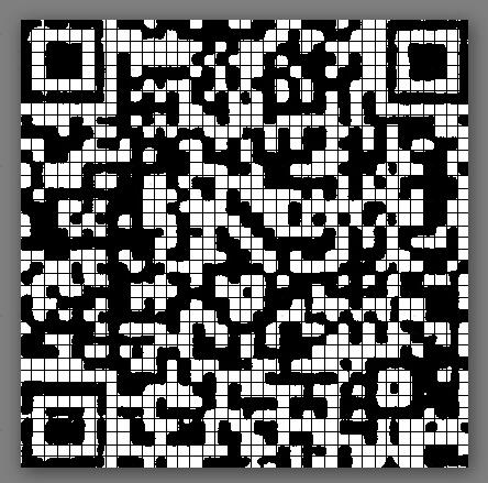
当预处理完成后,其实我们已经拿到一个比较正经的图像了如果二维码本身没有什么太大的缺陷,此时应当是可以直接扫描出来的
但是由于各种各样的原因,zbar无法直接识别图像,还需要我们对图像进行解析
最简单的方法就是识别图片中的每一行、每一列,记录对应的行列分割线
算法简述如下,以行搜索为例:
以上一行的下沿 + 一定的偏移量 作为起始行,从起始行的每一列开始寻找连续性的白点或者黑点,当出现黑白点切换时,认为已经抵达了当前行的下沿,将当前的行index添加到一个数组当中
循环完每一列之后,取当前所有下沿数据数组的中位数和平均数,取其较大值,即我们认为下沿应当是偏激进的
# 寻找rows
def found_point_rows(mat):
    temp1 = []
    i = 0
    normal_gap = 5
    last_gap = 0
    while i < mat.shape[0]:
        if i + 11 < mat.shape[0]:
            if i < mat.shape[0] - 20:
                gap = normal_gap
            else:
                gap = last_gap
            point_row = Point_rows(mat[int(i) + gap:min(int(i) + 18, 406), :], min(12, 406 - int(i)))
            mat_temp = point_row + gap
        else:
            break
        if mat_temp is None:
            i = i + 11
        else:
            i = i + mat_temp
            temp1.append(i)
    return temp1

def Point_rows(mat, border):
    lower_limit_j = []
    for i in range(0, mat.shape[1]):
        for j2 in range(0, min(border, mat.shape[0]) - 1):
            if mat[0:j2 + 1, i].mean() == 255 and mat[j2 + 1, i] == 0 and j2 > 2:  # 如果这一列,超过5个全是白色,下一个是黑色  则认为也到了边界
                lower_limit_j.append(j2)
                break
            elif mat[j2, i] == 0 and mat[j2 + 1, i] == 255 and j2 > 2:  # 如果这个是黑色而且下一个是白色,并且黑色数量大于五个,则认为到达了下限边界
                lower_limit_j.append(j2)
                break
    if len(lower_limit_j) == 0:
        return 6
    return max(int(np.median(np.array(lower_limit_j))), int((np.array(lower_limit_j).mean())))
如果当前图像是一个残损的图像,即左侧的定位点不完整,是无法确认生成了36列定位线的,需要根据左侧的坐标点重新计算定位线
坐标点的规则是,7~29的单数格子都为白,其他格子都为黑,当我们扫描某一列的分割点时,判定是否每个点都符合这个规律,确定正确的点给予1的积分,确定错误的点给予0的积分,不确定的给予0.5的积分,最终合并积分数量大于某个阈值,可以判定当前列就是定位线列:
def scan_anchor_point(image, point_rows, point_columns):
    # 按列扫描,统计每个格子的数据,统计37个格子的匹配度
    # i为行,j为列
    match_count_min = 30
    for j in range(0, len(point_columns)):

        match_count = 0
        for i in range(0, len(point_rows)):
            start_x = 0 if j == 0 else point_columns[j - 1] + 1
            end_x = point_columns[j]
            start_y = 0 if i == 0 else point_rows[i - 1] + 1
            end_y = point_rows[i]

            # 计算当前格子的匹配度
            # 白色格子坐标为 7 ~ 29之间的单数
            mean_color = image[start_y:end_y, start_x:end_x].mean();
            if mean_color < 50:
                color = "black"
            elif mean_color > 150:
                color = "white"
            else:
                color = "middle"

            if color == "middle":
                match_count += 0.8
            elif color == "white":
                if i >= 7 and i <= 29 and i / 2 != int(i / 2):
                    match_count += 1
                else:
                    match_count += 0
            else:
                if i >= 7 and i <= 29 and i / 2 != int(i / 2):
                    match_count += 0
                else:
                    match_count += 1

        if match_count > match_count_min:
            return start_x

    return None
最终根据列数、行数、以及图片的残损情况来调整图片的row和column的分割数组
    # 找到图片的XY分割线
    def find_split_lines(self, image, defect_flag):

        point_rows = split.found_point_rows(image)
        point_columns = split.found_point_columns(image)

        # 如果找出来的行列分割线多一个,删除掉最后一条线
        if len(point_columns) == 37:
            point_columns.pop(36)

        if len(point_rows) == 37:
            point_rows.pop(36)

        # 生成划线图
        draw_line_image = np.copy(image)
        for rowIndex in range(0, len(point_rows)):
            cv2.line(draw_line_image, (0, point_rows[rowIndex]), (406, point_rows[rowIndex]), (0, 0, 0), 1)
        for colIndex in range(0, len(point_columns)):
            cv2.line(draw_line_image, (point_columns[colIndex], 0), (point_columns[colIndex], 406), (0, 0, 0), 1)
        if self.trace_image:
            cv2.imwrite(self.trace_path + "501_draw_line_" + self.image_name, draw_line_image)

        # 判断当前图像是否缺损,缺损的话寻找坐标点重建图像
        if defect_flag:
            start_x = loc.scan_anchor_point(image, point_rows, point_columns)
            # 如果当前图像缺损,且未找到坐标点,返回空
            if start_x == None:
                print("未找到定位坐标点")
                return None
            else:
                # 找到坐标点,对图片进行缩放处理
                # 切掉图片左侧的校验区域,后续自动补齐
                fixed_image = np.zeros((407, 341), np.uint8)
                source_pst = np.float32([[start_x, 0], [start_x, 406], [406, 0], [406, 406]])
                target_pst = np.float32([[0, 0], [0, 406], [341, 0], [341, 406]])
                fixed_m = cv2.getPerspectiveTransform(source_pst, target_pst)
                fixed_image = cv2.warpPerspective(image, fixed_m, (341, 407))

                # 将图片恢复二值化
                ret2, th2 = cv2.threshold(fixed_image, 0, 255, cv2.THRESH_BINARY + cv2.THRESH_OTSU)
                ret3, fixed_image = cv2.threshold(th2, 0, 255, cv2.THRESH_BINARY + cv2.THRESH_OTSU)
                if self.trace_image:
                    cv2.imwrite(self.trace_path + "502_threshed_fixed_" + self.image_name, fixed_image)

                # 重新计算一次关键信息坐标点
                point_rows = split.found_point_rows(fixed_image)
                point_columns = split.found_point_columns(fixed_image)

                # 删除多余的分割线
                if defect_flag and len(point_columns) == 31:
                    point_columns.pop(30)

                if not defect_flag and len(point_columns) == 37:
                    point_columns.pop(36)

                if len(point_rows) == 37:
                    point_rows.pop(36)

                defect_draw_line_image = np.copy(fixed_image)
                for rowIndex in range(0, len(point_rows)):
                    cv2.line(defect_draw_line_image, (0, point_rows[rowIndex]), (406, point_rows[rowIndex]),
                             (0, 0, 0), 1)
                for colIndex in range(0, len(point_columns)):
                    cv2.line(defect_draw_line_image, (point_columns[colIndex], 0), (point_columns[colIndex], 406),
                             (0, 0, 0),
                             1)
                if self.trace_image:
                    cv2.imwrite(self.trace_path + "503_defect_draw_line_" + self.image_name, defect_draw_line_image)

        else:
            fixed_image = image

        # 根据XY定位点修复row/column
        (point_rows, point_columns) = split.fix_rows_columns(fixed_image, point_rows, point_columns,
                                                             defect_flag)

        # 如果非残缺图片,必须有36个分割线
        # 如果为残缺图片,必须有30个分割线

        if (not defect_flag and len(point_columns) != 36) or (defect_flag and len(point_columns) != 30):
            print("列数量不匹配")
            return None

        if len(point_rows) != 36:
            print("行数量不匹配")
            return None

        # 增补中止线
        point_rows.append(407)
        if not defect_flag:
            point_columns.append(407)
        else:
            point_columns.append(341)

return fixed_image, point_rows, point_columns目前这种算法在二维码图片整齐的时候比较好用,如果纸张出现了折叠、揉搓导致的物理偏移目前是没有很好的修复手段。因为物理偏移是无法使用投影变换恢复回来的,只能在寻找每一行每一列的时候,通过线段的延展方向来构造弯曲的分割线来做识别,思考了一下比较复杂,而且目前也没有遇到这种问题,暂时就没有改进
