CCS5.4+Proteus8的F28027实践课六、实验板焊接调试(12864部分)
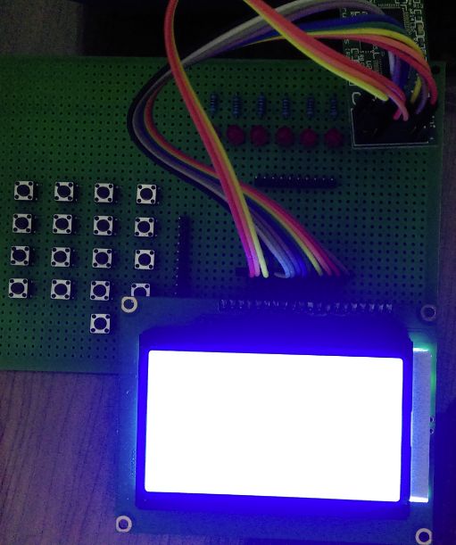
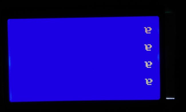
下班早早回家就是为了把昨天没做完的事情搞完,但等我把12864调完之后,好想找块豆腐撞死算了,RS引脚跳线不知道什么时候被我弄断了,我竟然一直没有检查板子,只顾着对着时序图和寄存器检查程序,哎,直接给大家上效果图吧。


由于12864有背光,一张是站的比较远拍的,一张是贴着12864屏幕拍的。
看完效果图了,直接给大家上程序吧,总共有四个文件。
1、GPIO.c
void InitGpio(void)
{
   EALLOW;

   // Each GPIO pin can be:
   // a) a GPIO input/output
   // b) peripheral function 1
   // c) peripheral function 2
   // d) peripheral function 3
   // By default, all are GPIO Inputs
   GpioCtrlRegs.GPAMUX1.all = 0x0000;     // GPIO functionality GPIO0-GPIO15
   GpioCtrlRegs.GPAMUX2.all = 0x0000;     // GPIO functionality GPIO16-GPIO31
   //GpioCtrlRegs.GPBMUX1.all = 0x0000;     // GPIO functionality GPIO32-GPIO34
   //GpioCtrlRegs.AIOMUX1.all = 0x0000;     // Dig.IO funct. applies to AIO2,4,6,10,12,14

   GpioCtrlRegs.GPADIR.all = 0xFFFFFFFF;      // GPIO0-GPIO31 are GP outputs
   //GpioCtrlRegs.GPBDIR.all = 0x0000;      // GPIO32-GPIO34 are inputs
   //GpioCtrlRegs.AIODIR.all = 0x0000;      // AIO2,4,6,19,12,14 are digital inputs

   // Each input can have different qualification
   // a) input synchronized to SYSCLKOUT
   // b) input qualified by a sampling window
   // c) input sent asynchronously (valid for peripheral inputs only)
   //GpioCtrlRegs.GPAQSEL1.all = 0x0000;    // GPIO0-GPIO15 Synch to SYSCLKOUT
   //GpioCtrlRegs.GPAQSEL2.all = 0x0000;    // GPIO16-GPIO31 Synch to SYSCLKOUT
   //GpioCtrlRegs.GPBQSEL1.all = 0x0000;    // GPIO32-GPIO34 Synch to SYSCLKOUT

   // Pull-ups can be enabled or disabled.
   GpioCtrlRegs.GPAPUD.all = 0xffffff00;      // Pullup's enabled GPIO0-GPIO31
   //GpioCtrlRegs.GPBPUD.all = 0x0000;      // Pullup's enabled GPIO32-GPIO34
   //GpioCtrlRegs.GPAPUD.all = 0xFFFF;    // Pullup's disabled GPIO0-GPIO31
   //GpioCtrlRegs.GPBPUD.all = 0xFFFF;    // Pullup's disabled GPIO32-GPIO34

   GpioDataRegs.GPADAT.all = 0x00000000;

   EDIS;

}
2、我自己写的F2802x_LCD12864.h
#ifndef F2802x_LCD12864_H
#define F2802x_LCD12864_H

#define RS GpioDataRegs.GPADAT.bit.GPIO16
#define RW GpioDataRegs.GPADAT.bit.GPIO17
#define EN GpioDataRegs.GPADAT.bit.GPIO18

void WRITEDATA_LCD12864(unsigned char data);
void WRITECMD_LCD12864(unsigned char cmd);
void InitLCD12864(void);

#endif  // end of F2802x_LCD12864_H definition
3、我自己写的F2802x_LCD12864.c
#include "F2802x_Device.h"     // Headerfile Include File
#include "F2802x_Examples.h"   // Examples Include File

//---------------------------------------------------------------------------
// WRITEDATA_LCD12864:
//---------------------------------------------------------------------------
// This function writes data to LCD12864
void WRITEDATA_LCD12864(unsigned char data)
{
    unsigned long int tmp;
//  tmp=GpioDataRegs.GPADAT.all;
    tmp=data;
    DELAY_US(1000);
    RS=1;
    RW=0;
    EN=0;
    GpioDataRegs.GPADAT.all=GpioDataRegs.GPADAT.all&0xffffff00;
    DELAY_US(1);
    GpioDataRegs.GPADAT.all=GpioDataRegs.GPADAT.all|(0x000000ff&tmp);
    DELAY_US(10);
    EN=1;
    DELAY_US(10);
    EN=0;
    DELAY_US(1000);
}

//---------------------------------------------------------------------------
// WRITECMD_LCD12864:
//---------------------------------------------------------------------------
// This function writes cmd to LCD12864
void WRITECMD_LCD12864(unsigned char cmd)
{
    unsigned long int tmp;
//  tmp=GpioDataRegs.GPADAT.all;
    tmp=cmd;
    DELAY_US(1000);
    RS=0;
    RW=0;
    EN=0;
    GpioDataRegs.GPADAT.all=GpioDataRegs.GPADAT.all&0xffffff00;
    DELAY_US(1);
    GpioDataRegs.GPADAT.all=GpioDataRegs.GPADAT.all|(0x000000ff&tmp);
    DELAY_US(10);
    EN=1;
    DELAY_US(10);
    EN=0;
    DELAY_US(1000);
}


//---------------------------------------------------------------------------
// InitLCD12864:
//---------------------------------------------------------------------------
// This function initializes the LCD12864 to a known (default) state.
// such as FUNCTION SET,DSIPLAY SET,CLEAR SCREEN

void InitLCD12864(void)
{
    DELAY_US(10000);
    WRITECMD_LCD12864(0x30);
    DELAY_US(1000);
    WRITECMD_LCD12864(0x30);
    DELAY_US(100);
    WRITECMD_LCD12864(0x0c);
    DELAY_US(1000);
    WRITECMD_LCD12864(0x01);
    DELAY_US(10000);
    WRITECMD_LCD12864(0x06);
    DELAY_US(10000);
}
4、主函数main.c
#include "DSP28x_Project.h"     // Device Headerfile and Examples Include File

void main(void)
{

// Step 1. Initialize System Control:
// PLL, WatchDog, enable Peripheral Clocks
// This example function is found in the DSP2802x_SysCtrl.c file.
   InitSysCtrl();

// Step 2. Initalize GPIO:
// This example function is found in the DSP2802x_Gpio.c file and
// illustrates how to set the GPIO to it's default state.
   InitGpio();

// Step 3. Clear all interrupts and initialize PIE vector table:
// Disable CPU interrupts
   DINT;

// Initialize PIE control registers to their default state.
// The default state is all PIE interrupts disabled and flags
// are cleared.
// This function is found in the DSP2802x_PieCtrl.c file.
   InitPieCtrl();

// Disable CPU interrupts and clear all CPU interrupt flags:
   IER = 0x0000;
   IFR = 0x0000;

// Initialize the PIE vector table with pointers to the shell Interrupt
// Service Routines (ISR).
// This will populate the entire table, even if the interrupt
// is not used in this example.  This is useful for debug purposes.
// The shell ISR routines are found in DSP2802x_DefaultIsr.c.
// This function is found in DSP2802x_PieVect.c.
   InitPieVectTable();


// Step 4. Initialize all the Device Peripherals:
// This function is found in DSP2802x_InitPeripherals.c
// InitPeripherals(); // Not required for this example

// Step 5. User specific code:

   InitLCD12864();

   WRITECMD_LCD12864(0x80);
   WRITEDATA_LCD12864('a');
   WRITECMD_LCD12864(0x90);
   WRITEDATA_LCD12864('a');
   WRITECMD_LCD12864(0x88);
   WRITEDATA_LCD12864('a');
   WRITECMD_LCD12864(0x98);
   WRITEDATA_LCD12864('a');

   while(1)
   {
//     GpioDataRegs.GPATOGGLE.all=0x000000ff;
//       DELAY_US(1000);
   }
}
经过验证,上面12864并行驱动文件是可用的,但是也只是最基础的驱动,像描点、画图、写字符串之类的,大家可以在我的基础上进行补充。等后面我们其他的课程需要串行驱动的时候,我们再来整理串行12864的驱动。今晚先这样了,我要去整理周四答辩的胶片和周五要提交给客户的报告。
菜鸟交流qq群107691092