CCS5.4+Proteus8的F28027实践课四、并行驱动LCD12864
趁着时间早,晚上九点四十,我们整理下12864的驱动程序,争取也弄成一个跟TI提供的类似源文件,然后共享给大家。
既然是12864,那最重要的肯定是12864时序的解读,在大学时期,12864还玩的真的很多,有并行驱动和串行驱动两种方式,今晚主要讲的是并行驱动,如果整理完了,时间还充足,我们也顺便一起把串行也整理了,毕竟F28027总共才22个GPIO端口,能省则省。
来,那我们再来啰嗦一把,一起看下12864相关资料。
首先看下它的管脚图:
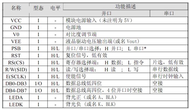
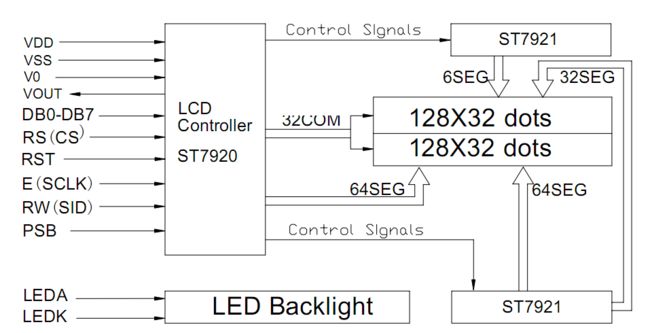
很容易看懂管脚作用吧,我们就不废话了,直接看时序图了。
先看写操作时序:
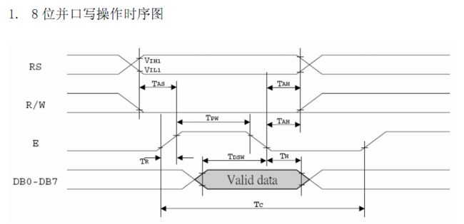
看完了写时序,我们应该顺便把写LCD数据和指令的子函数写出来
//---------------------------------------------------------------------------
// WRITEDATA_LCD12864:
//---------------------------------------------------------------------------
// This function writes data to LCD12864
void WRITEDATA_LCD12864(unsigned char data)
{
    GpioDataRegs.GPADAT.bit.GPIO16=1;
    GpioDataRegs.GPADAT.bit.GPIO17=1;
    GpioDataRegs.GPADAT.bit.GPIO18=0;
    DELAY_US(100);
    GpioDataRegs.GPADAT.bit.GPIO17=0;
    GpioDataRegs.GPADAT.bit.GPIO18=1;
    DELAY_US(1);
    GpioDataRegs.GPADAT.all=GpioDataRegs.GPADAT.all&0xffffff00;
    GpioDataRegs.GPADAT.all=GpioDataRegs.GPADAT.all|data;
    DELAY_US(1);
    GpioDataRegs.GPADAT.bit.GPIO17=1;
    GpioDataRegs.GPADAT.bit.GPIO18=0;
    DELAY_US(1000);
}

//---------------------------------------------------------------------------
// WRITECMD_LCD12864:
//---------------------------------------------------------------------------
// This function writes cmd to LCD12864
void WRITECMD_LCD12864(unsigned char cmd)
{
    GpioDataRegs.GPADAT.bit.GPIO16=0;
    GpioDataRegs.GPADAT.bit.GPIO17=1;
    GpioDataRegs.GPADAT.bit.GPIO18=0;
    DELAY_US(100);
    GpioDataRegs.GPADAT.bit.GPIO17=0;
    GpioDataRegs.GPADAT.bit.GPIO18=1;
    DELAY_US(1);
    GpioDataRegs.GPADAT.all=GpioDataRegs.GPADAT.all&0xffffff00;
    GpioDataRegs.GPADAT.all=GpioDataRegs.GPADAT.all|cmd;
    DELAY_US(1);
    GpioDataRegs.GPADAT.bit.GPIO17=1;
    GpioDataRegs.GPADAT.bit.GPIO18=0;
    DELAY_US(1000);
}
再看读时序:
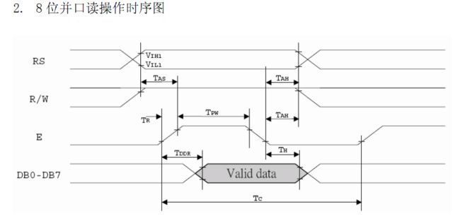
好,看完了时序图,我们紧接着就去看它的基本操作指令集:


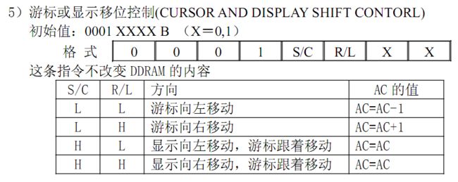


基本操作指令集就到这了,我们现在来了解下如何写12864驱动程序。
首先是LCD的初始化

根据上面的写函数,LCD的初始化就比较简单了
//---------------------------------------------------------------------------
// InitLCD12864:
//---------------------------------------------------------------------------
// This function initializes the LCD12864 to a known (default) state.
// such as FUNCTION SET,DSIPLAY SET,CLEAR SCREEN

void InitLCD12864(void)
{
    DELAY_US(10000);
    WRITECMD_LCD12864(0x30);
    DELAY_US(1000);
    WRITECMD_LCD12864(0x30);
    DELAY_US(100);
    WRITECMD_LCD12864(0x0c);
    DELAY_US(1000);
    WRITECMD_LCD12864(0x01);
    DELAY_US(10000);
    WRITECMD_LCD12864(0x06);
    DELAY_US(10000);
}
12864相关程序写完了,就可以直接去写主函数了,我这里比较简单,只让它显示一个字符而已
void main(void)
{

// Step 1. Initialize System Control:
// PLL, WatchDog, enable Peripheral Clocks
// This example function is found in the DSP2802x_SysCtrl.c file.
   InitSysCtrl();

// Step 2. Initalize GPIO:
// This example function is found in the DSP2802x_Gpio.c file and
// illustrates how to set the GPIO to it's default state.
   InitGpio();

// Step 3. Clear all interrupts and initialize PIE vector table:
// Disable CPU interrupts
   DINT;

// Initialize PIE control registers to their default state.
// The default state is all PIE interrupts disabled and flags
// are cleared.
// This function is found in the DSP2802x_PieCtrl.c file.
   InitPieCtrl();

// Disable CPU interrupts and clear all CPU interrupt flags:
   IER = 0x0000;
   IFR = 0x0000;

// Initialize the PIE vector table with pointers to the shell Interrupt
// Service Routines (ISR).
// This will populate the entire table, even if the interrupt
// is not used in this example.  This is useful for debug purposes.
// The shell ISR routines are found in DSP2802x_DefaultIsr.c.
// This function is found in DSP2802x_PieVect.c.
   InitPieVectTable();


// Step 4. Initialize all the Device Peripherals:
// This function is found in DSP2802x_InitPeripherals.c
// InitPeripherals(); // Not required for this example

// Step 5. User specific code:

   InitLCD12864();

   WRITECMD_LCD12864(0x80);
   WRITEDATA_LCD12864('a');

   while(1)
   {
//     GpioDataRegs.GPATOGGLE.all=0x000000ff;
//       DELAY_US(1000);
   }
}
到这里,相关的程序已经全部写完了,但是由于proteus没有我们常用12864的仿真库,所以打算明天直接用万用板搭一个测试平台出来,顺便把我们之前那几个实践课程的程序都验证下,期待我们明晚验证调试结果,调试完没问题后,就上传源代码,现在该洗洗睡了。
菜鸟交流qq群107691092