CCS5.4+Proteus8的F28027实践课十二、SCI
刚去健身房锻炼回来,一路都是烧纸,菩萨保佑,我一定好好学习。
今晚我们的主题是编写SCI基本驱动程序。
来来来,直接说了,今晚我们还是采用非中断回环模式,其实程序还是比较简单的,我先说下思路:
1、系统复位;
2、设置数据格式,包括停止位、奇偶校验位、回环测试模式、空闲线/地址为模式、字符串长度;
3、使能发送和接收;
4、设置波特率;
5、相关引脚设置;
6、编写发送子程序和接收子程序;
其实对应程序,只用到了几个寄存器,我们还是一起来看下.
首先是配置寄存器:

这个配置寄存器每一位我们都需要去设置,也就是我们刚才说的第二点;
然后是控制寄存器1:

这个寄存器里面设置发送接收使能和复位;
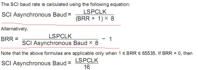
接着是波特率寄存器:


波特率就是按照计算公式,根据需要生成的波特率,自己算一下寄存器的取值;
下面是控制寄存器2:

主要是TXRDY位,发送准备位;
再下面是接收状态寄存器:

这里需要注意的也是接收准备位RXRDY;
最后需要注意的是发送寄存器和接收寄存器位宽不同
其中发送寄存器是8位宽的:

而接收状态寄存器是16位宽的:

好了,到这里寄存器相关需要注意的位也讲完了,现在开始写程序了。
程序比较简单,我刚刚去验证了,直接复制粘贴了
首先是DSP2802x_Sci.c文件
// TI File $Revision: /main/1 $
// Checkin $Date: August 14, 2008   16:58:46 $
//###########################################################################
//
// FILE:    DSP2802x_Sci.c
//
// TITLE:    DSP2802x SCI Initialization & Support Functions.
//
//###########################################################################
// $TI Release: f2802x Support Library v200 $
// $Release Date: Tue Jul 24 10:01:39 CDT 2012 $
//###########################################################################

#include "F2802x_Device.h"     // Headerfile Include File
#include "F2802x_Examples.h"   // Examples Include File

//---------------------------------------------------------------------------
// InitSci:
//---------------------------------------------------------------------------
// This function initializes the SCI(s) to a known state.
//
void InitSci(void)
{
    EALLOW;

    SciaRegs.SCICCR.bit.STOPBITS=0;     //one stop bit
    SciaRegs.SCICCR.bit.PARITY=0;
    SciaRegs.SCICCR.bit.PARITYENA=0;    //disable parity
    SciaRegs.SCICCR.bit.LOOPBKENA=1;    //loop back test mode
    SciaRegs.SCICCR.bit.ADDRIDLE_MODE=0; //idle-line mode
    SciaRegs.SCICCR.bit.SCICHAR=7;       //character-length is 8 bits

    SciaRegs.SCICTL1.bit.SWRESET = 0;   //reset the sci
    SciaRegs.SCICTL1.bit.SWRESET = 1;
    SciaRegs.SCICTL1.bit.RXENA=1;       //receiver enable
    SciaRegs.SCICTL1.bit.TXENA=1;       //transmitter enable
    SciaRegs.SCICTL1.bit.TXWAKE=0;

    SciaRegs.SCIHBAUD=0;
    SciaRegs.SCILBAUD=194;               //baud = 9600

    EDIS;
}

//---------------------------------------------------------------------------
// Example: InitSciGpio:
//---------------------------------------------------------------------------
// This function initializes GPIO pins to function as SCI pins
//
// Each GPIO pin can be configured as a GPIO pin or up to 3 different
// peripheral functional pins. By default all pins come up as GPIO
// inputs after reset.
//
// Caution:
// Only one GPIO pin should be enabled for SCITXDA/B operation.
// Only one GPIO pin shoudl be enabled for SCIRXDA/B operation.
// Comment out other unwanted lines.

void InitSciGpio()
{
   InitSciaGpio();
}

void InitSciaGpio()
{
   EALLOW;

/* Enable internal pull-up for the selected pins */
/* Disable internal pull-up for the selected output pins
   to reduce power consumption. */
// Pull-ups can be enabled or disabled disabled by the user.

//    GpioCtrlRegs.GPAPUD.bit.GPIO28 = 0;    // Enable pull-up for GPIO28 (SCIRXDA)
//    GpioCtrlRegs.GPAPUD.bit.GPIO19 = 0;    // Enable pull-up for GPIO19 (SCIRXDA)
    GpioCtrlRegs.GPAPUD.bit.GPIO7 = 0;     // Enable pull-up for GPIO7  (SCIRXDA)

//    GpioCtrlRegs.GPAPUD.bit.GPIO29 = 1;       // Disable pull-up for GPIO29 (SCITXDA)
//    GpioCtrlRegs.GPAPUD.bit.GPIO18 = 1;       // Disable pull-up for GPIO18 (SCITXDA)
    GpioCtrlRegs.GPAPUD.bit.GPIO12 = 1;       // Disable pull-up for GPIO12 (SCITXDA)

/* Set qualification for selected pins to asynch only */
// Inputs are synchronized to SYSCLKOUT by default.
// This will select asynch (no qualification) for the selected pins.

//    GpioCtrlRegs.GPAQSEL2.bit.GPIO28 = 3;  // Asynch input GPIO28 (SCIRXDA)
//    GpioCtrlRegs.GPAQSEL2.bit.GPIO19 = 3;  // Asynch input GPIO19 (SCIRXDA)
    GpioCtrlRegs.GPAQSEL1.bit.GPIO7 = 3;   // Asynch input GPIO7 (SCIRXDA)

/* Configure SCI-A pins using GPIO regs*/
// This specifies which of the possible GPIO pins will be SCI functional pins.

//    GpioCtrlRegs.GPAMUX2.bit.GPIO28 = 1;   // Configure GPIO28 for SCIRXDA operation
//    GpioCtrlRegs.GPAMUX2.bit.GPIO19 = 2;   // Configure GPIO19 for SCIRXDA operation
    GpioCtrlRegs.GPAMUX1.bit.GPIO7 = 2;    // Configure GPIO7  for SCIRXDA operation

//    GpioCtrlRegs.GPAMUX2.bit.GPIO29 = 1;   // Configure GPIO29 for SCITXDA operation
//    GpioCtrlRegs.GPAMUX2.bit.GPIO18 = 2;   // Configure GPIO18 for SCITXDA operation
    GpioCtrlRegs.GPAMUX1.bit.GPIO12 = 2;   // Configure GPIO12 for SCITXDA operation

    EDIS;
}

//===========================================================================
// End of file.
//===========================================================================
然后是主函数main.c文件
#include "DSP28x_Project.h"     // Device Headerfile and Examples Include File

void SCI_SendByte(unsigned char TxByte);
unsigned char SCI_ReadByte();

void main(void)
{

// Step 1. Initialize System Control:
// PLL, WatchDog, enable Peripheral Clocks
// This example function is found in the DSP2802x_SysCtrl.c file.
   InitSysCtrl();

// Step 2. Initalize GPIO:
// This example function is found in the DSP2802x_Gpio.c file and
// illustrates how to set the GPIO to it's default state.
   InitGpio();

// Step 3. Clear all interrupts and initialize PIE vector table:
// Disable CPU interrupts
   DINT;

// Initialize PIE control registers to their default state.
// The default state is all PIE interrupts disabled and flags
// are cleared.
// This function is found in the DSP2802x_PieCtrl.c file.
   InitPieCtrl();

// Disable CPU interrupts and clear all CPU interrupt flags:
   IER = 0x0000;
   IFR = 0x0000;

// Initialize the PIE vector table with pointers to the shell Interrupt
// Service Routines (ISR).
// This will populate the entire table, even if the interrupt
// is not used in this example.  This is useful for debug purposes.
// The shell ISR routines are found in DSP2802x_DefaultIsr.c.
// This function is found in DSP2802x_PieVect.c.
   InitPieVectTable();


// Step 4. Initialize all the Device Peripherals:
// This function is found in DSP2802x_InitPeripherals.c
// InitPeripherals(); // Not required for this example

// Step 5. User specific code:

   InitSci();
   InitSciGpio();
   InitLCD12864();

   WRITECMD_LCD12864(0x83);

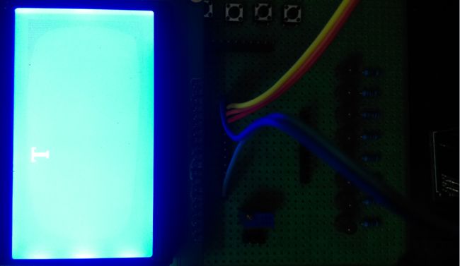
   SCI_SendByte('T');
   WRITEDATA_LCD12864(SCI_ReadByte());
   while(1);
}

void SCI_SendByte(unsigned char TxByte)
{
    while(SciaRegs.SCICTL2.bit.TXRDY != 1);   //Transmitter ready flag
    SciaRegs.SCITXBUF = TxByte;
}

unsigned char SCI_ReadByte()
{
    unsigned char RxByte;
    while(SciaRegs.SCIRXST.bit.RXRDY != 1);   // receiver ready flag
    RxByte = SciaRegs.SCIRXBUF.all&0x00ff;
    return(RxByte);
}
简单的SCI测试就完成了,明天我们学习I2C,都是同一类型的,原理都想通,明天学习验证就知道了,今晚中元节,早点洗洗睡了。
F28027菜鸟交流qq群107691092
