1,TMS320F28069 学习--------InitSysCtrl();
建工程的时候用到一个GPIO的例程
其中调用的第一个函数就是InitSysCtrl(); 今天详细了解一下这个函数都干了什么事情
void
InitSysCtrl(void)
{
    //
    // Disable the watchdog
    //
    DisableDog();

    //
    // *IMPORTANT*
    // The Device_cal function, which copies the ADC & oscillator calibration
    // values from TI reserved OTP into the appropriate trim registers, occurs
    // automatically in the Boot ROM. If the boot ROM code is bypassed during
    // the debug process, the following function MUST be called for the ADC and
    // oscillators to function according to specification. The clocks to the
    // ADC MUST be enabled before calling this function.
    // See the device data manual and/or the ADC Reference
    // Manual for more information.
    //
    EALLOW;
    SysCtrlRegs.PCLKCR0.bit.ADCENCLK = 1; // Enable ADC peripheral clock
    (*Device_cal)();
    SysCtrlRegs.PCLKCR0.bit.ADCENCLK = 0; // Return ADC clock to original state
    EDIS;

    //
    // Select Internal Oscillator 1 as Clock Source (default), and turn off all
    // unused clocks to conserve power.
    //
    IntOsc1Sel();

    //
    // Initialize the PLL control: PLLCR and CLKINDIV
    // DSP28_PLLCR and DSP28_CLKINDIV are defined in F2806x_Examples.h
    //
    InitPll(DSP28_PLLCR,DSP28_DIVSEL);

    //
    // Initialize the peripheral clocks
    //
    InitPeripheralClocks();
}
先是调用了下面这个函数
void
DisableDog(void)
{
    EALLOW;
    SysCtrlRegs.WDCR= 0x0068;
    EDIS;
}
#define EALLOW __asm(" EALLOW") -->猜测是EN ALLOW 的缩写 使能允许位,就是把EALLOW Bit 置1 ,去保护
#define EDIS __asm(" EDIS") -->猜测是 EN DISABLE的缩写 使能禁用位,就是把EALLOW Bit置0,写保护
器件仿真寄存器、FLASH寄存器、CSM寄存器、PIE 矢量表、系统控制寄存器、GPIO MUX 寄存器、在操作这些寄存器之前需要去保护,操作完需要写保护

SysCtrlRegs.WDCR= 0x0068;
WDPS 000 WDCLK = OSCCLK/512/1 (default)
WDCHK 101 You must ALWAYS write 1,0,1
WDDIS 1 Disables the watchdog module.
WDFLAG 0

接下来这段
    EALLOW;
    SysCtrlRegs.PCLKCR0.bit.ADCENCLK = 1; // Enable ADC peripheral clock
    (*Device_cal)();
    SysCtrlRegs.PCLKCR0.bit.ADCENCLK = 0; // Return ADC clock to original state
    EDIS;
SysCtrlRegs.PCLKCR0.bit.ADCENCLK = 1;
SysCtrlRegs.PCLKCR0.bit.ADCENCLK = 0;
开启ADC的时钟 很奇怪啊 为什么要把ADC的时钟打开软后又关了
仔细看,上面有段话 标注 important
仔细看了一下 大概的意思是 Device_cal 函数存在TI的预留存储中用来校准ADC和振荡器的
追踪一下这个函数 #define Device_cal (void (*)(void))0x3D7C80 是一个函数指针 位置是0x3D7C80
好 接下来
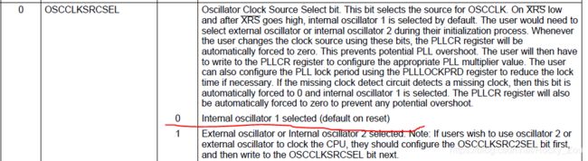
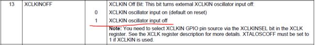
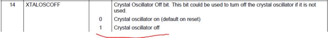
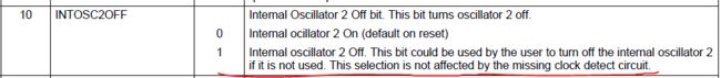
IntOsc1Sel(); 初始化振荡器
void
IntOsc1Sel(void)
{
EALLOW;
SysCtrlRegs.CLKCTL.bit.INTOSC1OFF = 0;
SysCtrlRegs.CLKCTL.bit.OSCCLKSRCSEL=0; // Clk Src = INTOSC1
SysCtrlRegs.CLKCTL.bit.XCLKINOFF=1; // Turn off XCLKIN
SysCtrlRegs.CLKCTL.bit.XTALOSCOFF=1; // Turn off XTALOSC
SysCtrlRegs.CLKCTL.bit.INTOSC2OFF=1; // Turn off INTOSC2
EDIS;
}


现在内部时钟已经到了锁相环的入口处(PLL) 果然下一句就是配置PLL的
InitPll(DSP28_PLLCR,DSP28_DIVSEL);
void
InitPll(Uint16 val, Uint16 divsel)
{
volatile Uint16 iVol;
// Make sure the PLL is not running in limp mode
if (SysCtrlRegs.PLLSTS.bit.MCLKSTS != 0)
{
EALLOW;
// OSCCLKSRC1 failure detected. PLL running in limp mode.
// Re-enable missing clock logic.
SysCtrlRegs.PLLSTS.bit.MCLKCLR = 1;
EDIS;
// Replace this line with a call to an appropriate
// SystemShutdown(); function.
__asm(" ESTOP0"); // Uncomment for debugging purposes
}
// DIVSEL MUST be 0 before PLLCR can be changed from
// 0x0000. It is set to 0 by an external reset XRSn
// This puts us in 1/4
if (SysCtrlRegs.PLLSTS.bit.DIVSEL != 0)
{
EALLOW;
SysCtrlRegs.PLLSTS.bit.DIVSEL = 0;
EDIS;
}
//
// Change the PLLCR
//
if (SysCtrlRegs.PLLCR.bit.DIV != val)
{
EALLOW;
//
// Before setting PLLCR turn off missing clock detect logic
//
SysCtrlRegs.PLLSTS.bit.MCLKOFF = 1;
SysCtrlRegs.PLLCR.bit.DIV = val;
EDIS;
//
// Optional: Wait for PLL to lock.
// During this time the CPU will switch to OSCCLK/2 until
// the PLL is stable. Once the PLL is stable the CPU will
// switch to the new PLL value.
//
// This time-to-lock is monitored by a PLL lock counter.
//
// Code is not required to sit and wait for the PLL to lock.
// However, if the code does anything that is timing critical,
// and requires the correct clock be locked, then it is best to
// wait until this switching has completed.
//
//
// Wait for the PLL lock bit to be set.
//
//
// The watchdog should be disabled before this loop, or fed within
// the loop via ServiceDog().
//
//
// Uncomment to disable the watchdog
//
DisableDog();
while(SysCtrlRegs.PLLSTS.bit.PLLLOCKS != 1)
{
//
// Uncomment to service the watchdog
//
//ServiceDog();
}
EALLOW;
SysCtrlRegs.PLLSTS.bit.MCLKOFF = 0;
EDIS;
}
//
// If switching to 1/2
//
if((divsel == 1)||(divsel == 2))
{
EALLOW;
SysCtrlRegs.PLLSTS.bit.DIVSEL = divsel;
EDIS;
}
//
// If switching to 1/1
// * First go to 1/2 and let the power settle
// The time required will depend on the system, this is only an example
// * Then switch to 1/1
//
if(divsel == 3)
{
EALLOW;
SysCtrlRegs.PLLSTS.bit.DIVSEL = 2;
DELAY_US(50L);
SysCtrlRegs.PLLSTS.bit.DIVSEL = 3;
EDIS;
}
}
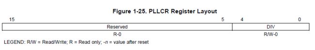
val = DSP28_PLLCR divsel = DSP28_DIVSEL 2
#define DSP28_PLLCR 18
#define DSP28_DIVSEL 2
if (SysCtrlRegs.PLLSTS.bit.MCLKSTS != 0) //确保PLL不工作在limp mode下,也就是有时钟输入到PLL,前面已经讲过
{
EALLOW;
SysCtrlRegs.PLLSTS.bit.MCLKCLR = 1; //如果时钟丢失就执行 ,清除标注位,再进行检测
EDIS; //程序注释,如果时钟丢失可以在这里添加停机函数,我目前没用到
__asm(" ESTOP0");
}
if (SysCtrlRegs.PLLSTS.bit.DIVSEL != 0) //不管分频是多少 都归零
{
EALLOW;
SysCtrlRegs.PLLSTS.bit.DIVSEL = 0;
EDIS;
}
if (SysCtrlRegs.PLLCR.bit.DIV != val) 设置倍频系数
{
EALLOW;
SysCtrlRegs.PLLSTS.bit.MCLKOFF = 1; //先关掉故障检测模块
SysCtrlRegs.PLLCR.bit.DIV = val;
EDIS;
DisableDog();
while(SysCtrlRegs.PLLSTS.bit.PLLLOCKS != 1)
{
//ServiceDog();
}
EALLOW;
SysCtrlRegs.PLLSTS.bit.MCLKOFF = 0;
EDIS;
}
接下来设置分频
if((divsel == 1)||(divsel == 2))
{
EALLOW;
SysCtrlRegs.PLLSTS.bit.DIVSEL = divsel;
EDIS;
}
//
// If switching to 1/1
// * First go to 1/2 and let the power settle
// The time required will depend on the system, this is only an example
// * Then switch to 1/1
//
if(divsel == 3)
{
EALLOW;
SysCtrlRegs.PLLSTS.bit.DIVSEL = 2;
DELAY_US(50L);
SysCtrlRegs.PLLSTS.bit.DIVSEL = 3;
EDIS;
}

PLL的框图
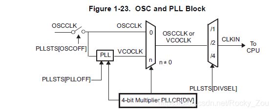
主频90MHz 就是这样配出来的
90 MHz devices [90 MHz = (10MHz * 18)/2]
接下来就是设置各个外设的时钟是否开启了,根据自己的需要自己配置即可,
InitPeripheralClocks();
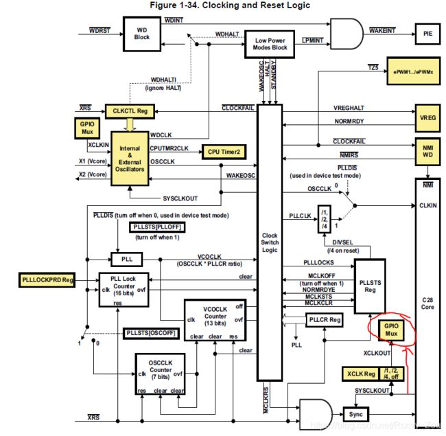
GPIO的时钟在下面这个图中标出了 是从SYSCLKOUT过去的
好了 今天就写到这里吧
2020.02.15