S3C2440之LCD简单操作篇
经过两天的努力终于把韦老师将的LCD搞懂了,下面简单的梳理和总结。
文章目录
- 1 模块化编程
- 1.1 不同芯片的LCD控制器的特征
- 1.2 不同型号的LCD的特征
- 2 在LCD上进行描点
- 3 测试LCD
1 模块化编程
模块化编程有着极大的好处,他不仅提高了代码的可读性,也提高了数据的安全性,还提高了程序的可移植性…,下面以模块化编程的方法来实现对LCD的操作。
在对LCD进行操作之前我们我们先构造好框架以实现模块化编程的特点,我们需要先建立出如下的C文件,这些C文件只能操作它对应的下一级的C文件,这使得各个C文件只关心自己的功能的实现,这极大地降低了编程的复杂度,而且当我们需要更换LCD或者主控芯片时也只需添加对应C文件,这也极大地降低了开发周期。
先抽象出不同尺寸的LCD的特征和每款芯片中LCD控制器的特征,然后将他们各自的特征封装在各自的结构体中以达到面向对象的编程效果。
1.1 不同芯片的LCD控制器的特征
这里我们以S3C2440中的LCD控制器为例来将它的特征抽象出来,对于LCD控制器我们需要函数来初始化、使能或者禁止它,所以我们需要在LCD控制器的结构体(lcd_controller)中定义这些函数的函数指针,然后再在对应芯片的LCD控制器的源文件(这里为s3c2440_lcd_controller.c)中来实现他们。
LCD控制器的结构体定如下(它被放在lcd_controller.h中)
#ifndef _LCD_CONTROLLER_H
#define _LCD_CONTROLLER_H

#include "lcd.h"
typedef struct lcd_controller
{
	char *name;
	void (*init)(p_lcd_params plcdparams);
	void (*enable)(void);
	void (*disable)(void);
	void (*init_palette)(void);		/* 初始化调色板函数 */
}lcd_controller, *p_lcd_controller;

#endif	/* _LCD_CONTROLLER_H */
对于具体某款芯片我们需要去对应芯片的lcd_congtroller.c中来实现上面结构体中的函数,这里以S3C2440为例进行设置。首先我们需要在s3c2440_lcd_controller.c中定义lcd_controller的结构体变量,如下(它被放在s3c2440_lcd_controller.c中)
lcd_controller s3c2440_lcd_controller = {
	.name		= "s3c2440",
	.init		= s3c2440_lcd_controller_init,
	.enable		= s3c2440_lcd_controller_enable,
	.disable 	= s3c2440_lcd_controller_disable,
	.init_palette = s3c2440_lcd_controller_init_palette,
};
然后我们需要根据S3C2440的芯片手册来设置这些函数,具体实现如下(它也被放在s3c2440_lcd_controller.c中)
#include "lcd.h"
#include "lcd_controller.h"
#include "../s3c2440_soc.h"

#define HCLK 100	/* 单位MHz */

void jz2440_lcd_pin_init(void)
{
	/* 初始化引脚 : 背光引脚GPB0 */
	GPBCON &= ~0x03;
	GPBCON |= 0x01;

	/* LCD专用引脚 */
	GPCCON = 0xaaaaaaaa;
	GPDCON = 0xaaaaaaaa;

	/* pwren */
	GPGCON |= (3<<8);
}

/* 根据传入的LCD参数设置LCD控制寄存器 */
void s3c2440_lcd_controller_init(p_lcd_params plcdparams)
{
	int clkval;
	int bppmode;
	int pixelplace;
	unsigned int addr;

	jz2440_lcd_pin_init();	/* 初始化引脚 */

	/* 设置LCD控制器时序 LCDCON1
	 * [17:8] : CLKVAL,	VCLK 	= HCLK / [(CLKVAL+1) x 2]
	 * 					9M  	= 100M / [(CLKVAL+1) x 2], CLKVAL = 4.5 = 5
	 *  			 CLKVAL		= HCLK / (vclk * 2) -1
	 * [6:5] :	PNRMODE, 11 = TFT LCD panel
	 * [4:1] : 	BPPMODE
	 * [0]	 :  ENVID, 1 = Enable the video output and the LCD control signal.
	 */
	clkval = (double)HCLK / (2 * plcdparams->time_seq.vclk) - 1 + 0.5;
	bppmode = plcdparams->bpp == 8		? 0xb : \
			  plcdparams->bpp == 16	? 0xc : \
			  0xd;		/* 0xd: 24bpp */
	 LCDCON1 = (clkval<<8) | (3<<5) | (bppmode<<1);

	/* 寄存器 LCDCON2 ,垂直方向设置
	 * [31:24] : VBPD = tvb - 1
	 * [23:14] : LINEVAL = tvd - 1
	 * [13:6]  : VFPD = tvf - 1
	 * [5:0]   : VSPW = tvp - 1
	 */
	LCDCON2 = ((plcdparams->time_seq.tvb - 1) << 24)	| \
			  ((plcdparams->yres - 1) << 14)			| \
			  ((plcdparams->time_seq.tvf - 1) << 6)	| \
			  ((plcdparams->time_seq.tvp - 1) << 0);


	/* 寄存器 LCDCON3 ,水平方向设置
	 * [25:19] : HBPD = thb - 1
	 * [18:8]  : HOZVAL = thd - 1
	 * [7:0]   : HFPD = thf - 1
	 */
	LCDCON3 = ((plcdparams->time_seq.thb - 1) << 19)	| \
			  ((plcdparams->xres - 1) << 8)			| \
			  ((plcdparams->time_seq.thf - 1) << 0);

	/* 寄存器 LCDCON4
	 * [7:0]   : HSPW = thp - 1
	 */
	LCDCON4 = ((plcdparams->time_seq.thp - 1) << 0);

	/* 寄存器 LCDCON5, 用来设置引脚极性,设置内存中像素存放格式
	 * [12] : BPP24BL
	 * [11] : FRM565,1 = 5:6:5 Format
	 * [10] : INVVCLK, 0 = The video data is fetched at VCLK falling edge
	 * [9]  : INVVLINE/INVHSYNC, 0 = Normal
	 * [8]	: INVVFRAME/INVVSYNC, 0 = Normal
	 * [7]	: INVVD, VD (video data),
	 * [6]	: INVVDEN,
	 * [5]	: INVPWREN
	 *
	 */
	pixelplace = plcdparams->bpp == 8	? (1<<1) 	: \
				 plcdparams->bpp == 16	? (1)	   : \
				 (0);		/*  24bpp */
	LCDCON5 = ((plcdparams->pins_pol.vclk) << 10)	 | \
			  ((plcdparams->pins_pol.hsync) << 9)	| \
			  ((plcdparams->pins_pol.vsync) << 8)	| \
			  ((plcdparams->pins_pol.rgb) << 7)		| \
			  ((plcdparams->pins_pol.de) << 6)		| \
        	   ((plcdparams->pins_pol.pwren) << 5)	 | \
			  (1<<11) | pixelplace;

	/* 设置framebuffer的地址
	 * [29:21] : LCDBANK,  A[30:22] of fb
	 * [20:0]  : LCDBASEU, A[21:1] of fb
	 */
	addr = plcdparams->fb_base & ~(1<<31);
	LCDSADDR1 = addr >> 1;

	/* [20:0]: LCDBASEL, A[21:1] of end fb */
	addr = plcdparams->fb_base + plcdparams->xres * plcdparams->yres * plcdparams->bpp / 8;
	addr >>= 1;
	addr &= 0x1fffff;
	LCDSADDR2 = addr;
}

/* 使能s3c2440_lcd_controller */
void s3c2440_lcd_controller_enable(void)
{
	/* 背光引脚, GPB0 */
	GPBDAT |= (1<<0);

	/* 使能pwren,给LCD提供AVDD */
	//LCDCON5 |= (1<<3);

	/* LCDCON1'bit0, 设置LCD控制控制器是否输出信号 */
	LCDCON1 |= (1<<0);
}

/* 禁止s3c2440_lcd_controller */
void s3c2440_lcd_controller_disable(void)
{
	/* 背光引脚, GPB0 */
	GPBDAT &= ~(1<<0);

	/* 禁止pwren,给LCD提供AVDD */
	//LCDCON5 &= ~(1<<3);

	/* LCDCON1'bit0, 设置LCD控制控制器是否输出信号 */
	LCDCON1 &= ~(1<<0);
}

/* 在设置调色板之前必须关掉lcd控制器,8BPP时需要用到 */
void s3c2440_lcd_controller_init_palette(void)
{
	int i, bit;
	volatile unsigned int *palette_base = (volatile unsigned int *)0x4D000400;

	bit = LCDCON1 & (1<<0);

	/* LCDCON1'bit0, 设置LCD控制控制器是否输出信号 */
	if (bit)	/* 如果之前是使能的则禁止 */
		LCDCON1 &= ~(1<<0);

	for (i = 0; i < 256; i++)
	{
		/* 低16位,rgb565 */
		*palette_base++ = i;	/* 初始化调试板中的颜色,这里设置的值效果不好 */
	}

	if (bit)	/* 如果之前是使能的则使能 */
		LCDCON1 |= (1<<0);
}
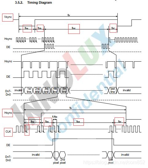
关于上面寄存器 LCDCON2、LCDCON3、LCDCON4的设置如下图,其中的极性也是需要我们关注的一点,在设置具体的LCD参数时需要以这里的极性为normal状态。

|
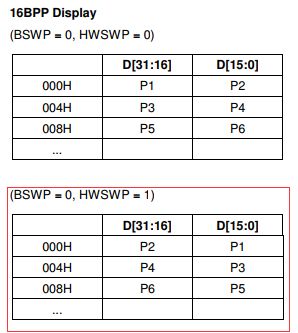
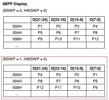
其中寄存器 LCDCON5中bpp模式的设置如下图所示,对于其中的24BPP我们用的是RGB:0x00RRGGBB的形式,对于16BPP我们使用的是RGB:565的形式,而对于8BPP我们需要用到调试板。

|

|

|
在实现完结构体lcd_controller中的函数后我们还需在lcd_controller.c中实现lcd控制器注册函数和选择函数,以供具体芯片的lcd控制器在其中注册和给lcd.c文件选择lcd控制器,最后用我们选择的lcd控制器来进行操作。如下(它被放在lcd_controller.c中)
#include "lcd.h"
#include "lcd_controller.h"

#define LCD_CONTROLLER_NUM 10

static p_lcd_controller p_lcd_controller_array[LCD_CONTROLLER_NUM];
static p_lcd_controller g_p_lcd_controller_selected;

int register_lcd_controller(p_lcd_controller plcdcontroller)
{
	int i;
	for (i = 0; i < LCD_CONTROLLER_NUM; i++)
	{
		if (!p_lcd_controller_array[i])
		{
			p_lcd_controller_array[i] = plcdcontroller;
			return i;
		}
	}
	return -1;
}

int select_lcd_controller(char *name)
{
	int i;
	for (i = 0; i < LCD_CONTROLLER_NUM; i++)
	{
		if (p_lcd_controller_array[i] && !strcmp(p_lcd_controller_array[i]->name, name))
		{
			g_p_lcd_controller_selected = p_lcd_controller_array[i];
			return i;
		}
	}
	return -1;
}
1.2 不同型号的LCD的特征
LCD的型号有多种,但是不同型号的LCD之间是有一定共同点的,这里我们以4.3寸LCD-AT043TN24为例进行特征抽象。这里我们先定义一个用来存放LCD参数的结构体(lcd_params),里面用来存放我们对不同型号LCD所抽象出的特征。一般不同的LCD都需要设置名字、引脚极性、时序、分辨率和framebuffer的起始地址,我们将这些参数放进叫lcd_params的结构体中,而引脚极性和时序又各自有各自的一些参数,所以我们还需要定义出关于引脚极性和时序的结构体:pins_polarity和time_sequence。
我们可以通过查看4.3寸LCD-AT043TN24的应用手册来在对应的结构体中设置对应的结构体变量(如下图)。

|

|
以下是我设置的相应结构体(其中xres=thd,yres=tvd,rgb为数据总线,bpp(bit pixel per)表示每个像素的位数)。它们被放在lcd.h中,当其他源文件要调用这些结构体时只需包含该头文件即可。
#ifndef _LCD_H
#define _LCD_H

enum {
	NORMAL = 0,
	INVERT = 1,
};

/* NORMAL : 正常
 * INVERT : 反转
 */
typedef struct pins_polarity
{
	int de;		/* normal: 高电平有效 */
	int pwren;	/* normal: 高电平有效 */
	int vclk;	/* normal: 在下降沿出获取数据 */
	int rgb;	/* normal: 高电平有效 */
	int vsync;	/* normal: 高脉冲 */
	int hsync; 	/* normal: 高脉冲 */
}pins_polarity, *p_pins_polarity;

typedef struct time_sequence
{
	int vclk;	/* Clock cycle */

	/* 垂直方向 */
	int tvp;	/* vsync脉冲宽度 */
	int tvb;	/* 上边黑框,Vertical Back porch */
	int tvf;	/* 下边黑框,Vertical Front porch */

	/* 水平方向 */
	int thp;	/* hsync脉冲宽度 */
	int thb;	/* 左边黑框,Horizontal Back porch */
	int thf;	/* 右边黑框,Horizontal Front porch */
}time_sequence, *p_time_sequence;

typedef struct lcd_params
{
	char *name;
	pins_polarity pins_pol;	/* 引脚极性 */
	time_sequence time_seq;	/* 时序 */

	/* 分辨率 */
	int xres;	/* 水平分辨率 */
	int yres;	/* 垂直分辨率 */
	int bpp;	/* bpp */

	unsigned int fb_base;	/* framebuffer的起始地址 */
}lcd_params, *p_lcd_params;

#endif  /* _LCD_H */
设置好结构体后我们需要在对应型号的LCD源文件中定义相应的结构变量并初始化,这里以JZ2440所用的4.3寸LCDAT043TN24为例来进行设置。(它被放在lcd_4.3.c中)
#include "lcd.h"

#define LCD_FB_BASE 0x33c00000	/* framebuffer的起始地址,设为没有使用过的任意一个地址都可以 */

lcd_params lcd_4_3_params = {
	.name = "lcd_4.3",

	/* 引脚极性 */
	.pins_pol = {
		.de		=  NORMAL ,	/* normal: 高电平有效 */
		//.pwren 	=  NORMAL ,	/* normal: 高电平有效 */
		.vclk 	=  NORMAL ,	/* normal: 在下降沿出获取数据 */
		.rgb 	=  NORMAL ,	/* normal: 高电平有效 */
		.vsync 	=  INVERT ,	/* normal: 高脉冲 */
		.hsync 	=  INVERT , /* normal: 高脉冲 */
	},

	/* 时序 */
	.time_seq = {
		.vclk = 9  ,	/* Clock cycle, 单位MHz */

		.tvp  = 10 ,	/* vsync脉冲宽度 */
		.tvb  = 2  ,	/* 上边黑框,Vertical Back porch */
		.tvf  = 2  ,	/* 下边黑框,Vertical Front porch */

		.thp  = 41 ,	/* hsync脉冲宽度 */
		.thb  = 2  ,	/* 左边黑框,Horizontal Back porch */
		.thf  = 2  ,	/* 右边黑框,Horizontal Front porch */
	},

	/* 分辨率 */
	.xres  = 480, /* 水平分辨率 */
	.yres  = 272, /* 垂直分辨率 */
	.bpp   = 16	,  /* 8/16/32bpp,禁止24bpp */

	/* framebuffer的起始地址 */
	.fb_base = LCD_FB_BASE
};
其中引脚极性需要以对应芯片中LCD控制器的极性为NORMAL状态,S3C2440中LCD控制器的相关极性在1.1中有介绍。
初始化具体lcd结构体变量后我们还需在lcd.c中实现lcd的注册函数和选择函数,以供具体型号的lcd在其中注册和给lcd.c文件选择具体型号的lcd,最后用我们选择的lcd的参数来初始化我们的lcd控制器,具体实现和上文讲LCD控制器时类似,这里不单独列出。对应的lcd初始化、使能、禁止和参数获取函数如下。(它被放在lcd.c中)
void get_lcd_params(unsigned int *fb_base, int *xres, int *yres, int *bpp)
{
	*fb_base = g_p_lcd_selected->fb_base;
	*xres 	= g_p_lcd_selected->xres;
	*yres 	= g_p_lcd_selected->yres;
	*bpp  	= g_p_lcd_selected->bpp;
}

void lcd_enable(void)
{
	lcd_controller_enable();
}

void lcd_disable(void)
{
	lcd_controller_disable();
}

void lcd_init(void)
{
	/* 注册lcd */
	lcd_4_3_add();

	/* 注册lcd controller */
	lcd_controller_add();

	/* 选择某款lcd */
	select_lcd("lcd_4.3");

	/* 选择某款lcd controller */
	select_lcd_controller("s3c2440");

	/* 使用lcd的参数,初始化lcd controller */
	lcd_controller_init(g_p_lcd_selected);
}
至此,对具体型号的LCD和某款芯片的LCD控制器我们都已经初始化好了,下面就是在LCD上的操作部分了,这里只介绍如何在LCD上描点。
2 在LCD上进行描点
LCD是由许多晶体管构成的,电子枪每打到这些晶体管上对应的晶体管就会发光发亮,电子枪是从左到右再从上到下一边移动一边发出颜色的,当它移动到屏幕的最右端后,再过thf时长LCD就会发出一个HSYNC(水平同步)脉冲,电子枪接收到该脉冲后就会跳到下一行的开始处,然后延时thb后继续工作,如此循环往复到屏幕最下端时再过tvf时长LCD又会发出一个VSYNC(垂直同步)脉冲,电子枪接收到后就会跳到屏幕的起始处,再延时tvb时长后继续重复性地工作。lcd的有效视图如下

|
具体的实现如下(它被放在framebuffer.c中)
#include "lcd.h"

/* 实现画点 */
static unsigned int fb_base;
static int xres, yres, bpp;

/* 获得参数 */
void fb_get_lcd_params(void)
{
	get_lcd_params(&fb_base, &xres, &yres, &bpp);
}

/* rgb: 0x00RRGGBB */
static unsigned short convert32bppto16bpp(unsigned int rgb)
{
	int r = (rgb >> 16) & 0xff;
	int g = (rgb >> 8) & 0xff;
	int b = rgb & 0xff;

	/* rgb: 565 */
	r >>= 3;
	g >>= 2;
	b >>= 3;

	return ((r<<11) | (g<<5) | (b));
}

void fb_put_pixel(int x, int y, unsigned int color)
{
	unsigned char  *pb;		/* 8bpp */
	unsigned short *pw;		/* 16bpp */
	unsigned int *pdw;		/* 32bpp */

	unsigned int pixel_base = fb_base + (xres * bpp / 8) * y + x * bpp / 8;

	switch (bpp)
	{
		case 8:
			pb = (unsigned char  *)pixel_base;
			*pb = color;
			break;

		case 16:
			pw = (unsigned short  *)pixel_base;
			*pw = convert32bppto16bpp(color);
			break;

		case 32:
			pdw = (unsigned int  *)pixel_base;
			*pdw = color;
			break;
	}
}
其中对于16BPP的模式,我们需要将32bit的color转换成16bit的,因为我们用的是rgb565的,所以可像上面一样转换。
对于画线、画原和写字其本质上都是在LCD上进行描点,这里不再介绍,对应的画线和画圆可参考这篇博客点我。
3 测试LCD
有了上面的基础后我们对于LCD的测试就变得很简单了,这里以16BPP模式输出整屏红色进行测试,
在测试时我们需要先初始化并使能LCD,具体实现如下。(它被放在lcd_test.c中)
void lcd_test(void)
{
	unsigned int fb_base;
	int xres, yres, bpp;
	int x, y;
	unsigned short *pw;

	/* 初始化lcd */
	lcd_init();

	/* 使能lcd */
	lcd_enable();

	/* 获得参数 */
	get_lcd_params(&fb_base, &xres, &yres, &bpp);
	fb_get_lcd_params();

	printf("bpp = %d\n\r", bpp);
	/* 往frambuffer写数据 */
	if (bpp == 16)
	{
		/* 让LCD输出整屏的红色, 565 : 0xf800 */
		pw = (unsigned short *)fb_base;
		for (y = 0; y < yres; y++)
		{
			for (x = 0; x < xres; x++)
			{
				*pw++ = 0xf800;
			}
	}
}