协议篇---OSPF综合实验
要求:
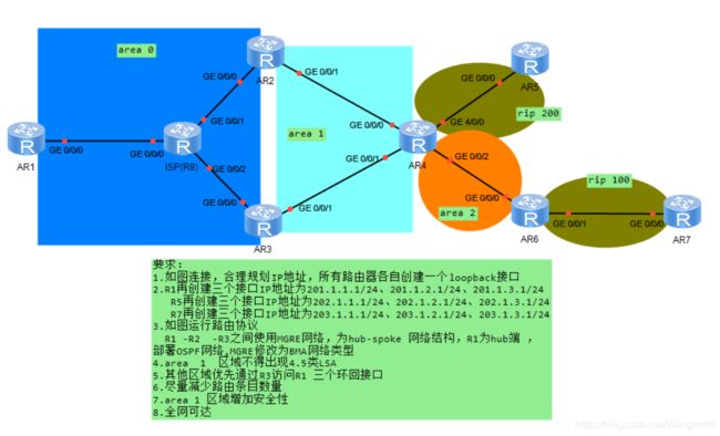
## 1.如图连接,合理规划IP地址,所有路由器各自创建一个loopback接口

## 2.R1再创建三个接口IP地址为201.1.1.1/24、201.1.2.1/24、201.1.3.1/24 R5再创建三个接口IP地址为202.1.1.1/24、202.1.2.1/24、202.1.3.1/24 R7再创建三个接口IP地址为203.1.1.1/24、203.1.2.1/24、203.1.3.1/24

## 3.如图运行路由协议 R1 -R2 -R3之间使用MGRE网络,为hub-spoke 网络结构,R1为hub端 ,部署OSPF网络,MGRE修改为BMA网络类型

## 4.area 1 区域不得出现4.5类LSA

## 5.其他区域优先通过R3访问R1 三个环回接口

## 6.尽量减少路由条目数量

## 7.area 1 区域增加安全性

## 8.全网可达
思路:
## 1、完成各路由器接口基础配置。
## 2、在R1,R2,R3上各写一条静态路由指向ISP(R8)。
## 3、在R1,R2,R3之间起MGRE网络。
## 4、在R1,R2,R3,R4,R6上起OSPF 100,并划分R1、R2、R3之间为area 0区域;R2、R3、R4之间为area 1区域;R4、R6之间为area 2区域。
## 5、在R1、R2、R3上修改网络类型和优先级,使R1为DR,R2、R3都为Dother。
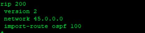
## 6、在R4、R5上起RIP 200,然后在R5上进行环回的路由汇总,以此减少路由条目,并在R4上进行双向重发布。
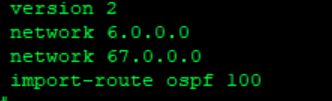
## 7、在R6、R7上起RIP 100,然后在R7上进行环回的路由汇总,以此减少路由条目,并在R6上进行双向重发布。
## 8、将R2、R3、R4之间的area 1区域设置为NSSA区域(过滤4、5类LSA),并在R2、R3的area 1区域对R1的环回路由进行汇总(汇总3类LSA)。
## 9、在R3、R4之间开启GRE,使其他区域优先通过R3访问R1的环回。
## 10、在R2、R3、R4之间的area 1区域做PPP认证,增加area 1区域安全性。
具体操作步骤:
第一步,基础配置
R1:
#
interface GigabitEthernet0/0/0
 ip address 18.1.1.1 255.255.255.0
interface LoopBack0
ip address 1.1.1.1 255.255.255.0
interface LoopBack1
 ip address 201.1.1.1 255.255.255.0
interface LoopBack2
 ip address 201.1.2.1 255.255.255.0
interface LoopBack3
 ip address 201.1.3.1 255.255.255.0
#
R2:
#
interface GigabitEthernet0/0/0
 ip address 28.1.1.1 255.255.255.0
interface GigabitEthernet0/0/1
 ip address 24.1.1.1 255.255.255.0
interface LoopBack0
 ip address 2.2.2.2 255.255.255.0
 #
R3:
#
interface GigabitEthernet0/0/0
 ip address 38.1.1.1 255.255.255.0
interface GigabitEthernet0/0/1
 ip address 34.1.1.1 255.255.255.0
interface LoopBack0
 ip address 3.3.3.3 255.255.255.0
 #
R4:
#
interface GigabitEthernet0/0/0
 ip address 24.1.1.2 255.255.255.0
interface GigabitEthernet0/0/1
 ip address 34.1.1.2 255.255.255.0
interface GigabitEthernet0/0/2
 ip address 46.1.1.1 255.255.255.0
interface GigabitEthernet4/0/0
 ip address 45.1.1.1 255.255.255.0
interface LoopBack0
 ip address 4.4.4.4 255.255.255.0
#
R5:
#
interface GigabitEthernet0/0/0
 ip address 45.1.1.2 255.255.255.0
interface LoopBack0
 ip address 5.5.5.5 255.255.255.0
interface LoopBack1
 ip address 202.1.1.1 255.255.255.0
interface LoopBack2
 ip address 202.1.2.1 255.255.255.0
interface LoopBack3
 ip address 202.1.3.1 255.255.255.0
#
R6:
#
interface GigabitEthernet0/0/0
 ip address 46.1.1.2 255.255.255.0
interface GigabitEthernet0/0/1
 ip address 67.1.1.1 255.255.255.0
interface LoopBack0
 ip address 6.6.6.6 255.255.255.0
#
R7:
#
interface GigabitEthernet0/0/0
 ip address 67.1.1.2 255.255.255.0
interface LoopBack0
 ip address 7.7.7.7 255.255.255.0
interface LoopBack1
 ip address 203.1.1.1 255.255.255.0
interface LoopBack2
 ip address 203.1.2.1 255.255.255.0
interface LoopBack3
 ip address 203.1.3.1 255.255.255.0
#
R8(ISP):
#
interface GigabitEthernet0/0/0
 ip address 18.1.1.2 255.255.255.0
interface GigabitEthernet0/0/1
 ip address 28.1.1.2 255.255.255.0
interface GigabitEthernet0/0/2
 ip address 38.1.1.2 255.255.255.0
#
在R1、R2、R3上写静态:
R1:
ip route-static 0.0.0.0 0.0.0.0 18.1.1.2
R2:
ip route-static 0.0.0.0 0.0.0.0 28.1.1.2
R3:
ip route-static 0.0.0.0 0.0.0.0 38.1.1.2
第二步:在R1,R2,R3之间起MGRE网络r8为ISP
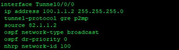
r1为hub端r2,r3为spoke端,配置hub-spoke网络结构
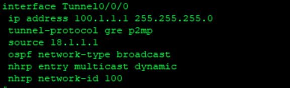
1、R1和R2、R3建立隧道修改网络类型hub端配置,如图
2、R 2spoke端配置(修改优先级为0让r1成为dr)
3、R3 spoke端设置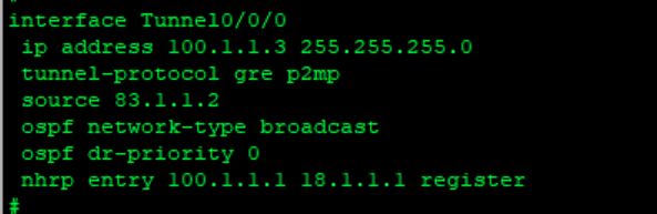
第三步:启用OSPF,并划分区域,并宣告环回以及隧道IP
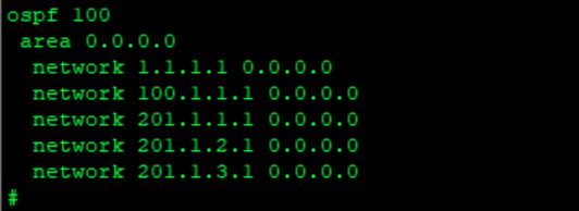
1、各个路由的OSPF配置
R1:
#
ospf 100 router-id 91.1.1.1
 area 0.0.0.0
  network 1.1.1.1 0.0.0.0
  network 100.1.1.1 0.0.0.0
  network 201.1.1.1 0.0.0.0
  network 201.1.2.1 0.0.0.0
  network 201.1.3.1 0.0.0.0
#
R2:
#
ospf 100 router-id 92.2.2.2
 area 0.0.0.0
  network 2.2.2.2 0.0.0.0
  network 100.1.1.2 0.0.0.0
 area 0.0.0.1
  authentication-mode simple plain 123 --------area 1区域做PPP认证
  network 24.1.1.1 0.0.0.0
  nssa
#
R3:
#
ospf 100 router-id 93.3.3.3
 area 0.0.0.0
  network 3.3.3.3 0.0.0.0
  network 100.1.1.3 0.0.0.0
 area 0.0.0.1
  authentication-mode simple plain 123 ---------area 1区域做PPP认证
  network 33.3.3.3 0.0.0.0
  network 34.1.1.1 0.0.0.0
  nssa
 area 0.0.0.2
  network 200.1.1.1 0.0.0.0
#
R4:
#
ospf 100 router-id 94.4.4.4
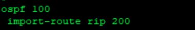
import-route rip 200
area 0.0.0.1
authentication-mode simple plain 123 -----------area 1区域做PPP认证
network 4.4.4.4 0.0.0.0
network 24.1.1.2 0.0.0.0
network 34.1.1.2 0.0.0.0
network 44.4.4.4 0.0.0.0
nssa
area 0.0.0.2
network 46.1.1.1 0.0.0.0
network 200.1.1.2 0.0.0.0
#
R6:
#
ospf 100 router-id 96.6.6.6
 import-route rip 100
 area 0.0.0.2
  network 46.1.1.2 0.0.0.0
#
2、ospf宣告每个路由的环回接口,宣告隧道ip到area0区域,如图:
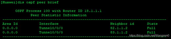
3、在R1上检查DR选举,如图:
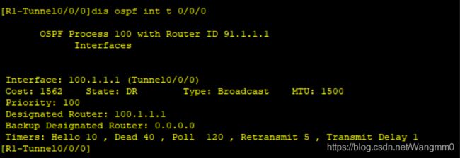
查看邻接关系是否建立,如图:
第四步:启用RIP
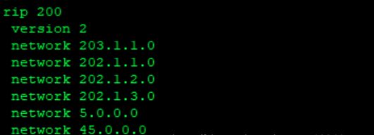
1、在R5上启用RIP 200
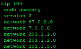
2、在R6.R7.上启用RIP 100
第五步:重发布
1、R4上将RIP 200导入OSPS 100中
2、R4上将OSPF 100导入RIP 200中
3、R6上将RIP 100导入OSPF 100中
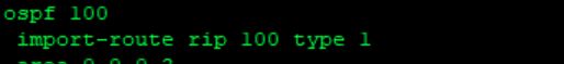
4、R6上将OSPF 100导入RIP 100中
第六步:解决不规则区域问题
在R3,R4上建立隧道解决不规则区域问题
1、R3配置,如图:
2、R4配置,如图:
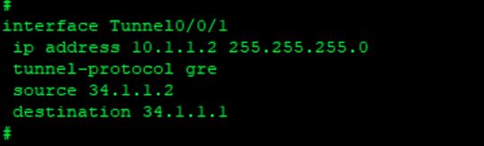
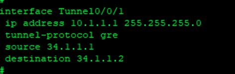
第七步:在R3、R4之间起GRE开通隧道,使其他区域优先通过R3访问R1的环回
R3:
#
interface Tunnel0/0/2
 ip address 33.3.3.3 255.255.255.0
 tunnel-protocol gre
 source 34.1.1.1
 destination 4.4.4.4
#
R4:
#
interface Tunnel0/0/2
 ip address 44.4.4.4 255.255.255.0
 tunnel-protocol gre
 source 4.4.4.4
 destination 34.1.1.1
#
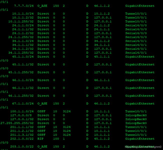
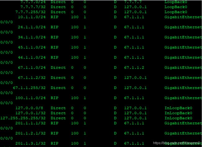
第八步:查看重发布不同协议,路由是否被学习
1、查看R4,如图:
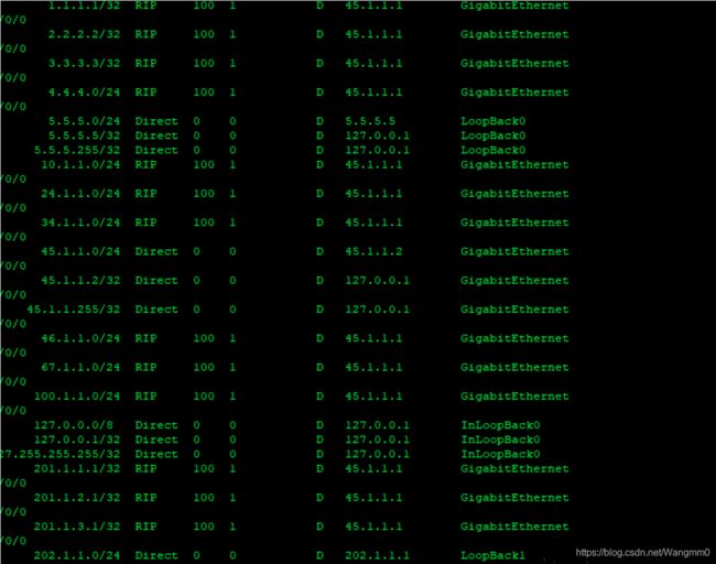
2、查看R5,如图:
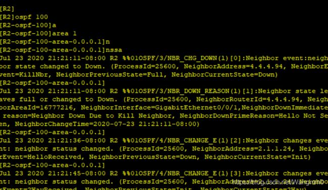
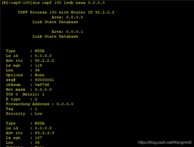
第九步:将area1设为nssa区域(过滤4类、5类LSA)
1、R2(R3,R4同R2操作一样),如图:
第十步:增加区域安全性
在R2、R3、R4的ospf 100的area 1区域做PPP认证:
#
ospf 100
area 1
authentication-mode simple plain 123
#
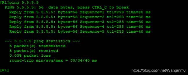
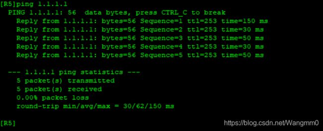
第十一步:测试全网互通(随机互ping),如图:
1、R1、R5互ping,如图: