DirectX11 几何体示例Demo
DirectX11 几何体示例Demo
我们将下来描述如何建立其他两个几何体形状:圆柱体和球体。这些形状对于天空盒、调试、可视化碰撞检测,和减少渲染是非常有帮助的。比如,你可能想把所有游戏角色都渲染成一个球体来调试测试。
1. 如何产生圆柱体网格?
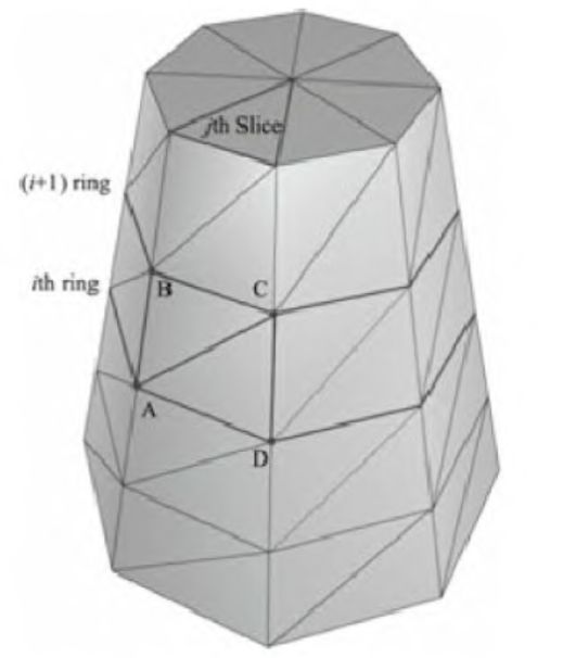
我们将圆柱体分为三个部分:侧面、顶部圆盖和底部圆盖。(注意这里说的圆柱体不是单纯的圆柱体,也可以泛指圆台、圆锥。当顶部圆盖半径为0就是圆锥。)我们可以定义一个圆柱体,通过指定其底部和顶部半径,还有高度,以及片(Slide)和层(Stack)数。如下图所示: 
(图中左边的圆柱体有8片,4层。片数和层数可以控制三角形的密度。)
2. 如何产生圆柱体侧面网格?
上图有【层数+1】个环(ring),每个环都有片数个顶点。
每两个连续的环的半径之差△r为:
△r = (顶部圆盖半径 - 底部圆盖半径) / 层数
如果底部的环的下标是0,那么第i个环半径r(i):
r(i) = 底部环半径+ iΔr。
△h是层的高度,h是圆柱体高度。那么第i个环的高度h(i)是:
h(i) = -h/2 + i△h
所以我们的基本实现就是迭代每一环来产生每一环上的顶点。
那么如何指定索引呢?
观察下图,每一层中的每一片都有一个四边形(两个三角形)。下图显示了第i层中的第j片: 
(顶点 A,B,C,D包含第i层中的第j片)
ΔABC=(i·n+j, (i+1)·n+j), (i+1)·n+j+1)
ΔACD=(i·n+j, (i+1)·n+j+1, i·n+j+1
n是每一环的顶点数。因此,创建索引缓存的关键的思想是每一层中的每一片应用上述公式。
注意:
1. 每个环的第一个和最后一个顶点在位置上重复,但纹理坐标不重复。我们必须这样做才能正确地使用纹理。
2. 代码中包含创建圆柱体对象额外的顶点数据,例如法线和纹理坐标,这些为以后的演示提供方便,现在不用担心这些代码。
3. 产生圆柱体侧面网格源代码
void GeometryGenerator::CreateCylinder(float bottomRadius, float topRadius, float height, UINT sliceCount, UINT stackCount, MeshData& meshData)
{
    meshData.Vertices.clear();
    meshData.Indices.clear();

    //
    // 建立层
    //

    float stackHeight = height / stackCount;

    // 根据层的级数,自底向上增加半径的步长
    float radiusStep = (topRadius - bottomRadius) / stackCount;

    UINT ringCount = stackCount+1;

    // 自底向上计算每个层环的顶点
    for(UINT i = 0; i < ringCount; ++i)
    {
        float y = -0.5f*height + i*stackHeight;
        float r = bottomRadius + i*radiusStep;

        // 环的顶点
        float dTheta = 2.0f*XM_PI/sliceCount;
        for(UINT j = 0; j <= sliceCount; ++j)
        {
            Vertex vertex;

            float c = cosf(j*dTheta);
            float s = sinf(j*dTheta);

            vertex.Position = XMFLOAT3(r*c, y, r*s);

            vertex.TexC.x = (float)j/sliceCount;
            vertex.TexC.y = 1.0f - (float)i/stackCount;

            vertex.TangentU = XMFLOAT3(-s, 0.0f, c);

            float dr = bottomRadius-topRadius;
            XMFLOAT3 bitangent(dr*c, -height, dr*s);

            XMVECTOR T = XMLoadFloat3(&vertex.TangentU);
            XMVECTOR B = XMLoadFloat3(&bitangent);
            XMVECTOR N = XMVector3Normalize(XMVector3Cross(T, B));
            XMStoreFloat3(&vertex.Normal, N);

            meshData.Vertices.push_back(vertex);
        }
    }

    // 因为第一个顶点和最后一个顶点的贴图坐标是不同的,我们将顶点数加1
    UINT ringVertexCount = sliceCount+1;

    // 计算每层的顶点
    for(UINT i = 0; i < stackCount; ++i)
    {
        for(UINT j = 0; j < sliceCount; ++j)
        {
            meshData.Indices.push_back(i*ringVertexCount + j);
            meshData.Indices.push_back((i+1)*ringVertexCount + j);
            meshData.Indices.push_back((i+1)*ringVertexCount + j+1);

            meshData.Indices.push_back(i*ringVertexCount + j);
            meshData.Indices.push_back((i+1)*ringVertexCount + j+1);
            meshData.Indices.push_back(i*ringVertexCount + j+1);
        }
    }

    //下面两个函数调用产生顶部圆盖和底部圆盖网格,接下来会说到
    BuildCylinderTopCap(bottomRadius, topRadius, height, sliceCount, stackCount, meshData);
    BuildCylinderBottomCap(bottomRadius, topRadius, height, sliceCount, stackCount, meshData);
}
4. 如何产生圆柱体顶部圆盖网格和底面圆盖网格?(源代码实现)
原理就是产生一个顶部环足够多的片来近似产生一个圆,我们直接看源代码,底部和顶部的代码是几乎一样的:
void GeometryGenerator::BuildCylinderTopCap(float bottomRadius, float topRadius, float height,
                                            UINT sliceCount, UINT stackCount, MeshData& meshData)
{
    UINT baseIndex = (UINT)meshData.Vertices.size();

    float y = 0.5f*height;
    float dTheta = 2.0f*XM_PI/sliceCount;

    // 因为圆柱体顶部的环顶点的贴图坐标和法线向量是不同的,我们要复制顶部的顶点
    for(UINT i = 0; i <= sliceCount; ++i)
    {
        float x = topRadius*cosf(i*dTheta);
        float z = topRadius*sinf(i*dTheta);

        // Scale down by the height to try and make top cap texture coord area proportional to base.
        float u = x/height + 0.5f;
        float v = z/height + 0.5f;

        meshData.Vertices.push_back( Vertex(x, y, z, 0.0f, 1.0f, 0.0f, 1.0f, 0.0f, 0.0f, u, v) );
    }

    // 盖中心的顶点
    meshData.Vertices.push_back( Vertex(0.0f, y, 0.0f, 0.0f, 1.0f, 0.0f, 1.0f, 0.0f, 0.0f, 0.5f, 0.5f) );

    // 中心顶点的索引
    UINT centerIndex = (UINT)meshData.Vertices.size()-1;

    for(UINT i = 0; i < sliceCount; ++i)
    {
        meshData.Indices.push_back(centerIndex);
        meshData.Indices.push_back(baseIndex + i+1);
        meshData.Indices.push_back(baseIndex + i);
    }
}
void GeometryGenerator::BuildCylinderBottomCap(float bottomRadius, float topRadius, float height,
UINT sliceCount, UINT stackCount, MeshData& meshData)
{
//
// 建立底部盖
//
UINT baseIndex = (UINT)meshData.Vertices.size();
float y = -0.5f*height;
// 环的顶点
float dTheta = 2.0f*XM_PI/sliceCount;
for(UINT i = 0; i <= sliceCount; ++i)
{
float x = bottomRadius*cosf(i*dTheta);
float z = bottomRadius*sinf(i*dTheta);
// Scale down by the height to try and make top cap texture coord area proportional to base.
float u = x/height + 0.5f;
float v = z/height + 0.5f;
meshData.Vertices.push_back( Vertex(x, y, z, 0.0f, -1.0f, 0.0f, 1.0f, 0.0f, 0.0f, u, v) );
}
// 盖中心的顶点
meshData.Vertices.push_back( Vertex(0.0f, y, 0.0f, 0.0f, -1.0f, 0.0f, 1.0f, 0.0f, 0.0f, 0.5f, 0.5f) );
// 中心顶点的索引缓存
UINT centerIndex = (UINT)meshData.Vertices.size()-1;
for(UINT i = 0; i < sliceCount; ++i)
{
meshData.Indices.push_back(centerIndex);
meshData.Indices.push_back(baseIndex + i);
meshData.Indices.push_back(baseIndex + i+1);
}
}5. 如何产生球体网格?
书中介绍了两种方法,一种是GeometryGenerator::CreateSphere,另外一种是GeometryGenerator::CreateGeosphere。
6. CreateSphere产生球体源代码实现
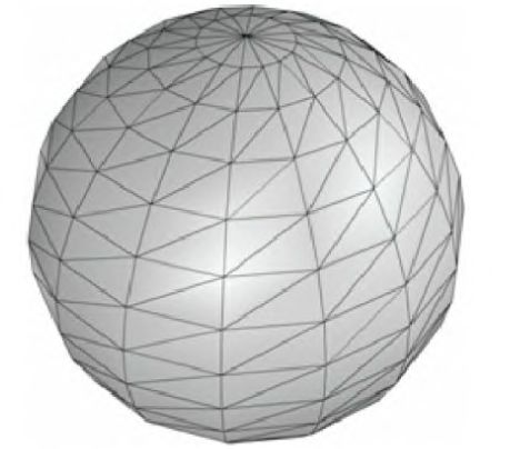
这个方法也是通过指定片数和层数来创建的,生成的算法和圆柱体生成算法是非常相似的,但每环的半径变化是依据三角函数产生的非线性变换。以CreateSphere这种方式产生的三角形不是等边三角形,三角形之间也未必相等,而以CreateGeosphere方式产生的三角形则是等边三角形,而且它们是全等三角形,可以参见下一幅图的Geosphere,比较一下两种球体网格的不同之处。这里只给出源代码,不再赘述。(英文注释未翻译部分并非当前章节所学的知识,暂时无需关注)
void GeometryGenerator::CreateSphere(float radius, UINT sliceCount, UINT stackCount, MeshData& meshData)
{
    meshData.Vertices.clear();
    meshData.Indices.clear();

    // 计算顶端的极端点,并且向下移动堆
    //

    // 极端点:注意贴图坐标可能会扭曲,因为正方形贴图映射到球体导致没有合适的位置映射到极端点。
    Vertex topVertex(0.0f, +radius, 0.0f, 0.0f, +1.0f, 0.0f, 1.0f, 0.0f, 0.0f, 0.0f, 0.0f);
    Vertex bottomVertex(0.0f, -radius, 0.0f, 0.0f, -1.0f, 0.0f, 1.0f, 0.0f, 0.0f, 0.0f, 1.0f);

    meshData.Vertices.push_back( topVertex );

    float phiStep   = XM_PI/stackCount;
    float thetaStep = 2.0f*XM_PI/sliceCount;

    // 计算每个栈环的顶点(不将极端点视为环)
    for(UINT i = 1; i <= stackCount-1; ++i)
    {
        float phi = i*phiStep;

        // 环的顶点
        for(UINT j = 0; j <= sliceCount; ++j)
        {
            float theta = j*thetaStep;

            Vertex v;

            // 球面到笛卡尔坐标系
            v.Position.x = radius*sinf(phi)*cosf(theta);
            v.Position.y = radius*cosf(phi);
            v.Position.z = radius*sinf(phi)*sinf(theta);

            // Partial derivative of P with respect to theta
            v.TangentU.x = -radius*sinf(phi)*sinf(theta);
            v.TangentU.y = 0.0f;
            v.TangentU.z = +radius*sinf(phi)*cosf(theta);

            XMVECTOR T = XMLoadFloat3(&v.TangentU);
            XMStoreFloat3(&v.TangentU, XMVector3Normalize(T));

            XMVECTOR p = XMLoadFloat3(&v.Position);
            XMStoreFloat3(&v.Normal, XMVector3Normalize(p));

            v.TexC.x = theta / XM_2PI;
            v.TexC.y = phi / XM_PI;

            meshData.Vertices.push_back( v );
        }
    }

    meshData.Vertices.push_back( bottomVertex );

    //
    // 计算堆的索引。堆顶是顶点缓存第一个数据,并且连接顶端的极端点到第一个环。
    //

    for(UINT i = 1; i <= sliceCount; ++i)
    {
        meshData.Indices.push_back(0);
        meshData.Indices.push_back(i+1);
        meshData.Indices.push_back(i);
    }

    //
    // 计算内堆的索引。(不包括极端点)

    // 第一个顶点到第一个环的索引偏移
    // 这里仅仅跳过顶端的极端顶点
    UINT baseIndex = 1;
    UINT ringVertexCount = sliceCount+1;
    for(UINT i = 0; i < stackCount-2; ++i)
    {
        for(UINT j = 0; j < sliceCount; ++j)
        {
            meshData.Indices.push_back(baseIndex + i*ringVertexCount + j);
            meshData.Indices.push_back(baseIndex + i*ringVertexCount + j+1);
            meshData.Indices.push_back(baseIndex + (i+1)*ringVertexCount + j);

            meshData.Indices.push_back(baseIndex + (i+1)*ringVertexCount + j);
            meshData.Indices.push_back(baseIndex + i*ringVertexCount + j+1);
            meshData.Indices.push_back(baseIndex + (i+1)*ringVertexCount + j+1);
        }
    }

    //
    // 计算底堆的索引。底堆是最后写到顶点缓存的,并且连接低端的极端点和底端环
    //

    // 南极端顶点是最后添加的
    UINT southPoleIndex = (UINT)meshData.Vertices.size()-1;

    // 第一个顶点到最后一个环的偏移索引
    baseIndex = southPoleIndex - ringVertexCount;

    for(UINT i = 0; i < sliceCount; ++i)
    {
        meshData.Indices.push_back(southPoleIndex);
        meshData.Indices.push_back(baseIndex+i);
        meshData.Indices.push_back(baseIndex+i+1);
    }
}
6. CreateGeosphere产生球体源代码实现
下图是Geosphere的产生过程。它的原理是通过二十面体来细分,再将细分后的顶点映射到一个球体。也可以重复这个过程来产生细分度更高的球体。 
我们通过取一个三角形的每条边的中点来产生四个小三角形,如下图: 
这时候这几个顶点都是在同一个平面的,接下来再将所有顶点位置向量的大小变为半径大小(这个过程相当于将20面体的所有新产生的顶点映射到球体表面),就产生了一个细分度更高的球体。
通过如下公式,可以将顶点位置向量的大小变为半径大小:
现在,我们有足够的知识来看源代码了:
void GeometryGenerator::CreateGeosphere(float radius, UINT numSubdivisions, MeshData& meshData)
{
    // Put a cap on the number of subdivisions.
    // 细分数
    numSubdivisions = MathHelper::Min(numSubdivisions, 5u);

    // Approximate a sphere by tessellating an icosahedron.
    // 通过细分二十面体来产生球体

    const float X = 0.525731f;
    const float Z = 0.850651f;

    XMFLOAT3 pos[12] =
    {
        XMFLOAT3(-X, 0.0f, Z),  XMFLOAT3(X, 0.0f, Z),
        XMFLOAT3(-X, 0.0f, -Z), XMFLOAT3(X, 0.0f, -Z),
        XMFLOAT3(0.0f, Z, X),   XMFLOAT3(0.0f, Z, -X),
        XMFLOAT3(0.0f, -Z, X),  XMFLOAT3(0.0f, -Z, -X),
        XMFLOAT3(Z, X, 0.0f),   XMFLOAT3(-Z, X, 0.0f),
        XMFLOAT3(Z, -X, 0.0f),  XMFLOAT3(-Z, -X, 0.0f)
    };

    DWORD k[60] =
    {
        1,4,0,  4,9,0,  4,5,9,  8,5,4,  1,8,4,
        1,10,8, 10,3,8, 8,3,5,  3,2,5,  3,7,2,
        3,10,7, 10,6,7, 6,11,7, 6,0,11, 6,1,0,
        10,1,6, 11,0,9, 2,11,9, 5,2,9,  11,2,7
    };

    meshData.Vertices.resize(12);
    meshData.Indices.resize(60);

    for(UINT i = 0; i < 12; ++i)
        meshData.Vertices[i].Position = pos[i];

    for(UINT i = 0; i < 60; ++i)
        meshData.Indices[i] = k[i];

    for(UINT i = 0; i < numSubdivisions; ++i)
        Subdivide(meshData);

    // 投射顶点到球体并且进行缩放

    for(UINT i = 0; i < meshData.Vertices.size(); ++i)
    {
        // 投射到单位球
        XMVECTOR n = XMVector3Normalize(XMLoadFloat3(&meshData.Vertices[i].Position));

        // 投射到符合半径的球体
        XMVECTOR p = radius*n;

        XMStoreFloat3(&meshData.Vertices[i].Position, p);
        XMStoreFloat3(&meshData.Vertices[i].Normal, n);

        // 从球面坐标导出纹理坐标
        float theta = MathHelper::AngleFromXY(
            meshData.Vertices[i].Position.x,
            meshData.Vertices[i].Position.z);

        float phi = acosf(meshData.Vertices[i].Position.y / radius);

        meshData.Vertices[i].TexC.x = theta/XM_2PI;
        meshData.Vertices[i].TexC.y = phi/XM_PI;

        // Partial derivative of P with respect to theta
        meshData.Vertices[i].TangentU.x = -radius*sinf(phi)*sinf(theta);
        meshData.Vertices[i].TangentU.y = 0.0f;
        meshData.Vertices[i].TangentU.z = +radius*sinf(phi)*cosf(theta);

        XMVECTOR T = XMLoadFloat3(&meshData.Vertices[i].TangentU);
        XMStoreFloat3(&meshData.Vertices[i].TangentU, XMVector3Normalize(T));
    }
}
7. Shape示例Demo
现在来看下这个Demo,它将展示多个球体和圆柱体,还有之前使用过的正方体。我们通过不同的世界坐标矩阵来绘制多个物体。
// 定义从局部坐标系转换到世界坐标系的矩阵
XMFLOAT4X4 mSphe reWorld[10];
XMFLOAT4X4 mCylWorld[10];
XMFLOAT4X4 mBoxWorld;
XMFLOAT4X4 mGridWorld;
XMFLOAT4X4 mCe nte rSphe re ;
XMMATRIX I = XMMatrixIde ntity();
XMStore Float4x4(&mGridWorld, I);
XMMATRIX boxScale = XMMatrixScaling(2.0f, 1.0f, 2.0f);
XMMATRIX boxOffset = XMMatrixTranslation(0.0f, 0.5f, 0.0f);
XMStore Float4x4(&mBoxWorld, XMMatrixMultiply(boxScale , boxOffset));
XMMATRIX ce nte rSphere Scale = XMMatrixScaling(2.0f, 2.0f, 2.0f);
XMMATRIX ce nte rSphere Offset = XMMatrixTranslation(0.0f, 2.0f, 0.0f);
XMStore Float4x4(&mCe nte rSphe re , XMMatrixMultiply(ce nte rSphe re Scale , cente rSphe re Offset));
// We create 5 rows of 2 cylinders and spheres per row.
for(inti=0;i<5;++i)
{
    XMStoreFloat4x4(&mCylWorld[i*2+0],
        XMMatrixTranslation(-5.0f, 1.5f, -10.0f + i*5.0f));
    XMStoreFloat4x4(&mCylWorld[i*2+1],
        XMMatrixTranslation(+5.0f, 1.5f, -10.0f + i*5.0f));
    XMStoreFloat4x4(&mSphere World[i*2+0],
        XMMatrixTranslation(-5.0f, 3.5f, -10.0f + i*5.0f));
    XMStoreFloat4x4(&mSphere World[i*2+1],
        XMMatrixTranslation(+5.0f, 3.5f, -10.0f + i*5.0f));
}
我们将所有的网格顶点和索引都放到同一个顶点和索引缓存,通过拼接顶点和索引数组。所以当我们绘制一个物体时,我们只是绘制顶点和索引缓冲区的子集。
下面的代码演示了如何创建几何缓冲区,以及如何绘制对象。
void ShapesApp::BuildGeometryBuffers()
{
    GeometryGenerator::MeshData box;
    GeometryGenerator::MeshData grid;
    GeometryGenerator::MeshData sphere;
    GeometryGenerator::MeshData cylinder;

    GeometryGenerator geoGen;
    geoGen.CreateBox(1.0f, 1.0f, 1.0f, box);
    geoGen.CreateGrid(20.0f, 30.0f, 60, 40, grid);
    geoGen.CreateSphere(0.5f, 20, 20, sphere);
    //geoGen.CreateGeosphere(0.5f, 2, sphere);
    geoGen.CreateCylinder(0.5f, 0.3f, 3.0f, 20, 20, cylinder);

    // 连续的顶点缓存中每个物体的顶点偏移缓存
    mBoxVertexOffset      = 0;
    mGridVertexOffset     = box.Vertices.size();
    mSphereVertexOffset   = mGridVertexOffset + grid.Vertices.size();
    mCylinderVertexOffset = mSphereVertexOffset + sphere.Vertices.size();

    // 每个物体的索引数量缓存
    mBoxIndexCount      = box.Indices.size();
    mGridIndexCount     = grid.Indices.size();
    mSphereIndexCount   = sphere.Indices.size();
    mCylinderIndexCount = cylinder.Indices.size();

    // 连续的索引缓存中每个物体的开始索引缓存
    mBoxIndexOffset      = 0;
    mGridIndexOffset     = mBoxIndexCount;
    mSphereIndexOffset   = mGridIndexOffset + mGridIndexCount;
    mCylinderIndexOffset = mSphereIndexOffset + mSphereIndexCount;

    UINT totalVertexCount =
        box.Vertices.size() +
        grid.Vertices.size() +
        sphere.Vertices.size() +
        cylinder.Vertices.size();

    UINT totalIndexCount =
        mBoxIndexCount +
        mGridIndexCount +
        mSphereIndexCount +
        mCylinderIndexCount;

    //
    // 提取我们感兴趣的顶点元素,并将所有网格顶点打包成一个顶点缓存
    //

    std::vector vertices(totalVertexCount);

    XMFLOAT4 black(0.0f, 0.0f, 0.0f, 1.0f);

    UINT k = 0;
    for(size_t i = 0; i < box.Vertices.size(); ++i, ++k)
    {
        vertices[k].Pos   = box.Vertices[i].Position;
        vertices[k].Color = black;
    }

    for(size_t i = 0; i < grid.Vertices.size(); ++i, ++k)
    {
        vertices[k].Pos   = grid.Vertices[i].Position;
        vertices[k].Color = black;
    }

    for(size_t i = 0; i < sphere.Vertices.size(); ++i, ++k)
    {
        vertices[k].Pos   = sphere.Vertices[i].Position;
        vertices[k].Color = black;
    }

    for(size_t i = 0; i < cylinder.Vertices.size(); ++i, ++k)
    {
        vertices[k].Pos   = cylinder.Vertices[i].Position;
        vertices[k].Color = black;
    }

    D3D11_BUFFER_DESC vbd;
    vbd.Usage = D3D11_USAGE_IMMUTABLE;
    vbd.ByteWidth = sizeof(Vertex) * totalVertexCount;
    vbd.BindFlags = D3D11_BIND_VERTEX_BUFFER;
    vbd.CPUAccessFlags = 0;
    vbd.MiscFlags = 0;
    D3D11_SUBRESOURCE_DATA vinitData;
    vinitData.pSysMem = &vertices[0];
    HR(md3dDevice->CreateBuffer(&vbd, &vinitData, &mVB));

    //
    // 打包所有网格的索引到一个索引缓存
    //

    std::vector indices;
    indices.insert(indices.end(), box.Indices.begin(), box.Indices.end());
    indices.insert(indices.end(), grid.Indices.begin(), grid.Indices.end());
    indices.insert(indices.end(), sphere.Indices.begin(), sphere.Indices.end());
    indices.insert(indices.end(), cylinder.Indices.begin(), cylinder.Indices.end());

    D3D11_BUFFER_DESC ibd;
    ibd.Usage = D3D11_USAGE_IMMUTABLE;
    ibd.ByteWidth = sizeof(UINT) * totalIndexCount;
    ibd.BindFlags = D3D11_BIND_INDEX_BUFFER;
    ibd.CPUAccessFlags = 0;
    ibd.MiscFlags = 0;
    D3D11_SUBRESOURCE_DATA iinitData;
    iinitData.pSysMem = &indices[0];
    HR(md3dDevice->CreateBuffer(&ibd, &iinitData, &mIB));
}
ShapesApp::ShapesApp(HINSTANCE hInstance)
: D3DApp(hInstance), mVB(0), mIB(0), mFX(0), mTech(0),
mfxWorldViewProj(0), mInputLayout(0), mWireframeRS(0),
mTheta(1.5f*MathHelper::Pi), mPhi(0.1f*MathHelper::Pi), mRadius(15.0f)
{
mMainWndCaption = L"Shapes Demo";
mLastMousePos.x = 0;
mLastMousePos.y = 0;
XMMATRIX I = XMMatrixIdentity();
XMStoreFloat4x4(&mGridWorld, I);
XMStoreFloat4x4(&mView, I);
XMStoreFloat4x4(&mProj, I);
XMMATRIX boxScale = XMMatrixScaling(2.0f, 1.0f, 2.0f);
XMMATRIX boxOffset = XMMatrixTranslation(0.0f, 0.5f, 0.0f);
XMStoreFloat4x4(&mBoxWorld, XMMatrixMultiply(boxScale, boxOffset));
XMMATRIX centerSphereScale = XMMatrixScaling(2.0f, 2.0f, 2.0f);
XMMATRIX centerSphereOffset = XMMatrixTranslation(0.0f, 2.0f, 0.0f);
XMStoreFloat4x4(&mCenterSphere, XMMatrixMultiply(centerSphereScale, centerSphereOffset));
for(int i = 0; i < 5; ++i)
{
XMStoreFloat4x4(&mCylWorld[i*2+0], XMMatrixTranslation(-5.0f, 1.5f, -10.0f + i*5.0f));
XMStoreFloat4x4(&mCylWorld[i*2+1], XMMatrixTranslation(+5.0f, 1.5f, -10.0f + i*5.0f));
XMStoreFloat4x4(&mSphereWorld[i*2+0], XMMatrixTranslation(-5.0f, 3.5f, -10.0f + i*5.0f));
XMStoreFloat4x4(&mSphereWorld[i*2+1], XMMatrixTranslation(+5.0f, 3.5f, -10.0f + i*5.0f));
}
}void ShapesApp::UpdateScene(float dt)
{
// Convert Spherical to Cartesian coordinates.
float x = mRadius*sinf(mPhi)*cosf(mTheta);
float z = mRadius*sinf(mPhi)*sinf(mTheta);
float y = mRadius*cosf(mPhi);
// Build the view matrix.
XMVECTOR pos = XMVectorSet(x, y, z, 1.0f);
XMVECTOR target = XMVectorZero();
XMVECTOR up = XMVectorSet(0.0f, 1.0f, 0.0f, 0.0f);
XMMATRIX V = XMMatrixLookAtLH(pos, target, up);
XMStoreFloat4x4(&mView, V);
}void ShapesApp::DrawScene()`
{
md3dImmediateContext->ClearRenderTargetView(mRenderTargetView, reinterpret_cast<const float*>(&Colors::LightSteelBlue));
md3dImmediateContext->ClearDepthStencilView(mDepthStencilView, D3D11_CLEAR_DEPTH|D3D11_CLEAR_STENCIL, 1.0f, 0);
md3dImmediateContext->IASetInputLayout(mInputLayout);
md3dImmediateContext->IASetPrimitiveTopology(D3D11_PRIMITIVE_TOPOLOGY_TRIANGLELIST);
md3dImmediateContext->RSSetState(mWireframeRS);
UINT stride = sizeof(Vertex);
UINT offset = 0;
md3dImmediateContext->IASetVertexBuffers(0, 1, &mVB, &stride, &offset);
md3dImmediateContext->IASetIndexBuffer(mIB, DXGI_FORMAT_R32_UINT, 0);
// Set constants
XMMATRIX view = XMLoadFloat4x4(&mView);
XMMATRIX proj = XMLoadFloat4x4(&mProj);
XMMATRIX viewProj = view*proj;
D3DX11_TECHNIQUE_DESC techDesc;
mTech->GetDesc( &techDesc );
for(UINT p = 0; p < techDesc.Passes; ++p)
{
// Draw the grid.
XMMATRIX world = XMLoadFloat4x4(&mGridWorld);
mfxWorldViewProj->SetMatrix(reinterpret_cast<float*>(&(world*viewProj)));
mTech->GetPassByIndex(p)->Apply(0, md3dImmediateContext);
md3dImmediateContext->DrawIndexed(mGridIndexCount, mGridIndexOffset, mGridVertexOffset);
// Draw the box.
world = XMLoadFloat4x4(&mBoxWorld);
mfxWorldViewProj->SetMatrix(reinterpret_cast<float*>(&(world*viewProj)));
mTech->GetPassByIndex(p)->Apply(0, md3dImmediateContext);
md3dImmediateContext->DrawIndexed(mBoxIndexCount, mBoxIndexOffset, mBoxVertexOffset);
// Draw center sphere.
world = XMLoadFloat4x4(&mCenterSphere);
mfxWorldViewProj->SetMatrix(reinterpret_cast<float*>(&(world*viewProj)));
mTech->GetPassByIndex(p)->Apply(0, md3dImmediateContext);
md3dImmediateContext->DrawIndexed(mSphereIndexCount, mSphereIndexOffset, mSphereVertexOffset);
// Draw the cylinders.
for(int i = 0; i < 10; ++i)
{
world = XMLoadFloat4x4(&mCylWorld[i]);
mfxWorldViewProj->SetMatrix(reinterpret_cast<float*>(&(world*viewProj)));
mTech->GetPassByIndex(p)->Apply(0, md3dImmediateContext);
md3dImmediateContext->DrawIndexed(mCylinderIndexCount, mCylinderIndexOffset, mCylinderVertexOffset);
}
// Draw the spheres.
for(int i = 0; i < 10; ++i)
{
world = XMLoadFloat4x4(&mSphereWorld[i]);
mfxWorldViewProj->SetMatrix(reinterpret_cast<float*>(&(world*viewProj)));
mTech->GetPassByIndex(p)->Apply(0, md3dImmediateContext);
md3dImmediateContext->DrawIndexed(mSphereIndexCount, mSphereIndexOffset, mSphereVertexOffset);
}
}
HR(mSwapChain->Present(0, 0));
}


