HDLbits代码答案(2.2Vectors & 2.3Modules: Hierarchy)持更
以下代码均通过波形检验,具备可参考性。部分知识点记录来自于HDLbits平台编写代码时所得,欢迎持续关注和错误指正。
附HDLBits官网:https://hdlbits.01xz.net/wiki/Problem_sets#Verilog_Language
Verilog Language
Vectors
① Vectors// 矢量表达
矢量用于分组相关的信号。例如,wire [7:0] w;声明一个名为w的8位向量。
注意:向量长度放在名称前,选择的部分位放于名称后,即:类型 [长度] 名称 [选择位]
当assign左右的向量不匹配,则截断或零扩展

module top_module (
    input wire [2:0] vec,
    output wire [2:0] outv,
    output wire o2,
    output wire o1,
    output wire o0  ); // Module body starts after module declaration

    assign outv [2:0] = vec [2:0];
    assign o2 = vec [2];
    assign o1 = vec [1];
    assign o0 = vec [0];

endmodule
波形:

② Vectors in more detail //矢量描述的更多细节
type [upper:lower] vector_name; 例子:input wire [3:-2] z; // negative ranges are allowed
大or小印第安序需要在代码中保持一致:big-endian, e.g., [0:3] or little-endian, e.g., [3:0]
Implicit nets: Verilog中没有定义的中间信号,均默认为1 bit wire(隐性线网)
为了防止隐性wire造成的bug,用语句`default_nettype none来避免线网类型不被声明
default_nettype 的其他用法详见https://www.cnblogs.com/xgcl-wei/p/9119024.html
Unpacked vs. Packed Arrays: 常用于声明内存阵列
reg [7:0] mem [255:0]; // 256 unpacked elements, each is a 8-bit packed vector of reg.
reg mem2 [28:0]; // 29 unpacked elements, each of which is a 1-bit reg.
详见http://www.asic-world.com/systemverilog/data_types10.html
Practice: 将一个组合逻辑的输入([15:0])分成下字节(7:0)和上字节(15:8)。
`default_nettype none     // Disable implicit nets. Reduces some types of bugs.
module top_module(
    input wire [15:0] in,
    output wire [7:0] out_hi,
    output wire [7:0] out_lo );

    assign out_hi = in [15:8];
    assign out_lo = in [7:0];

endmodule
波形:

③ Vector part select //部分矢量选择
module top_module(
    input [31:0] in,
    output [31:0] out );//

    assign out [31:24] = in [7:0];
    assign out [23:16] = in [15:8];
    assign out [15:8] = in [23:16];
    assign out [7:0] = in [31:24];

    //or assign out = {in[7:0], in[15:8], in[23:16], in[31:24]};

endmodule
④ Bitwise operators //逐位运算和逻辑运算
逻辑操作将整个向量视为一个布尔值(true or false)并产生1位的输出。

module top_module(
    input [2:0] a,
    input [2:0] b,
    output [2:0] out_or_bitwise,
    output out_or_logical,
    output [5:0] out_not
);

    assign out_or_bitwise = a | b;         // | -bit or
    assign out_or_logical = a || b;        // || -logical or
    assign out_not ={{~ b}, {~ a}};

endmodule
波形:

⑤ Four-input gates //建立4输入的组合电路
module top_module(
    input [3:0] in,
    output out_and,
    output out_or,
    output out_xor
);

    assign out_and = in[0] & in[1] & in[2] & in[3];
    assign out_or = in[0] | in[1] | in[2] | in[3];
    assign out_xor = in[0] ^ in[1] ^ in[2] ^ in[3];

endmodule
波形:

⑥ Vector concatenation operator //向量连接符 { }
e.g. {4’ha, 4’d10} => 8’b10101010
连接运算符可用于assign的左侧和右侧。
module top_module (
    input [4:0] a, b, c, d, e, f,
    output [7:0] w, x, y, z );//

    assign {w, x, y, z} = {a, b, c, d, e, f, 2'b11};

endmodule
波形:

⑦ Vector reversal 1 //矢量反序
module top_module(
    input [7:0] in,
    output [7:0] out
);

    assign out [7:0] = {in[0],in[1],in[2],in[3],in[4],in[5],in[6],in[7]};

    //assign out [7:0] = in [0:7]; 此处若用语句不合规

endmodule
注意:assign out [7:0] = in [0:7];虽然意思表示反序,但这是典型的软件思维,Verilog语法是不支持直接反序功能的。
波形:

⑧ Replication operator //复制运算符
格式:{ , {num{vector}, } num必须是常数,两个花括号都是必需的!!
复制运算符常用于数据延展,通过复制符号位来实现的数据延展 e.g. 无符号扩展:4’b0101 (5) to 8 bits --> 8’b00000101 (5)。有符号扩展:4’b1101 (-3) --> 8’b11111101 (-3).
Practice:实现8位数字扩展到32位
module top_module (
    input [7:0] in,
    output [31:0] out );//

    assign out = { {24{in[7]}} , in};  //24外面的一组花括号也不可以省略

endmodule
波形:
module top_module (
    input a, b, c, d, e,
    output [24:0] out );//

    assign out =~{{5{a}},{5{b}},{5{c}},{5{d}},{5{e}}} ^ {{5{a,b,c,d,e}}};
    //写这么长的语句,可视化程度较低

endmodule
波形:
Modules: Hierarchy
① Modules //模块
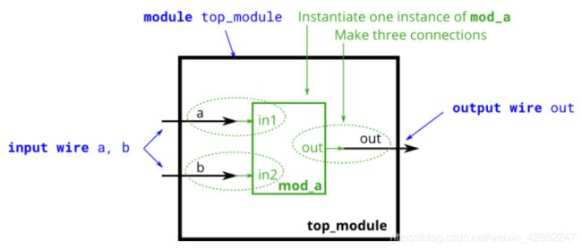
模块的层次结构是在一个模块中实例化另一个模块来体现的,两种例化方法:
1.by position : mod_a instance1 ( wa, wb, wc );
这种语法的缺点是,如果模块的端口列表发生了更改,需要找到所有例化模块进行相匹配的更改。
2.by name : mod_a instance2 ( .out(wc), .in1(wa), .in2(wb) );
这里端口的顺序可以更改,只要通过名称连接信号,能在端口列表改变的情况下保持正确连接,但是语法更冗长。

module top_module ( input a, input b, output out );

    mod_a instance1 (a,b,out);
    //   mod_a instance1 (.in1(a), .in2(b), .out(out));
endmodule
波形:

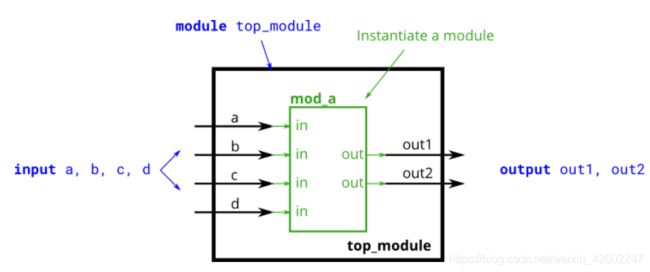
② Connecting ports by position //按位置例化

module top_module (
    input a,
    input b,
    input c,
    input d,
    output out1,
    output out2
);

    mod_a m1(out1,out2,a, b, c,d);

endmodule
波形:

③ Connecting ports by name //通过名称例化

module top_module (
    input a,
    input b,
    input c,
    input d,
    output out1,
    output out2
);

    mod_a m1( .out1(out1), .out2(out2), .in1(a), .in2(b), .in3(c), .in4(d));

endmodule
波形:

④ Three modules //链接3个FF module

module top_module ( input clk, input d, output q );

    wire q1,q2;

    my_dff ff1( .clk(clk), .d(d), .q(q1) );
    my_dff ff2( .clk(clk), .d(q1), .q(q2) );
    my_dff ff3( .clk(clk), .d(q2), .q(q) );

endmodule
波形:
⑤ Modules and vectors //链接3个FF并选择其中一个

module top_module (
    input clk,
    input [7:0] d,
    input [1:0] sel,
    output [7:0] q
);

    wire [7:0] q1,q2,q3;

    my_dff8 f1(clk,d,q1);
    my_dff8 f2(clk,q1,q2);
    my_dff8 f3(clk,q2,q3);

    always @ (sel or d)
    begin
        case (sel)     //这里的括号不能丢
            2'b00: q = d;                    //q是output wire型
            2'b01: q = q1;
            2'b10: q = q2;
            2'b11: q = q3;
            default: q = 8'bxxxx;
        endcase
    end

endmodule
module top_module(
    input [31:0] a,
    input [31:0] b,
    output [31:0] sum
);
    wire cout,cout2;

    add16 low(a[15:0],b[15:0],1'b0,sum[15:0],cout);
    add16 up(a[31:16],b[31:16],cout,sum[31:16],cout2);

endmodule
module top_module (
    input [31:0] a,
    input [31:0] b,
    output [31:0] sum
);//

    wire cout,cout1;

    add16 low (a[15:0], b[15:0], 1'b0, sum[15:0], cout);
    add16 up (a[31:16], b[31:16], cout, sum[31:16], cout1);

endmodule

module add1 ( input a, input b, input cin,   output sum, output cout );

    assign {cout,sum} = a + b + cin;

endmodule
波形:

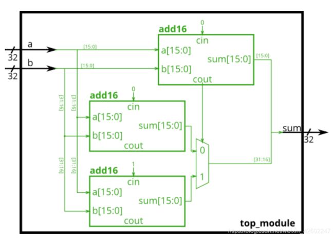
⑧ Carry-select adder //进位选择加法器

module top_module(
    input [31:0] a,
    input [31:0] b,
    output [31:0] sum
);

    wire cout,cout0,cout1;
    wire [15:0] sum0, sum1;

    add16 low (a[15:0], b[15:0], 1'b0, sum[15:0], cout);
    add16 up0 (a[31:16],b[31:16],1'b0,sum0,cout0);
    add16 up1 (a[31:16],b[31:16],1'b1,sum1,cout1);

    always @ (cout or sum0 or sum1)
    begin
    case (cout)
        0: sum[31:16] = sum0;
        1: sum[31:16] = sum1;
        default: sum[31:16] = 16'bxxxx;
    endcase
    end

endmodule
⑨ Adder-subtractor //有符号加法器 or 加减加法器
当b为负数时,对负数取反+1,计算两种操作:(a + b + 0) and (a + ~b + 1)
无符号的a和有符号的b相加:用异或实现两种操作的符号处理,异或:不同为1,相同为0,sub设为符号位。

module top_module(
    input [31:0] a,
    input [31:0] b,
    input sub,
    output [31:0] sum
);

    wire [31:0] b_sub;
    wire cout,cout2;

    assign b_sub = b ^ {32{sub}};
    add16 a1 (a[15:0], b_sub[15:0], sub, sum[15:0], cout);
    add16 a2 (a[31:16], b_sub[31:16], cout, sum[31:16], cout2);

endmodule
波形:

总结:
Verilog是搭建硬件,要有意识的锻炼硬件思维,以及增强代码可读性。
补:有两处波形缺失,写下一篇的时候补充。


