华为综合案例
华为综合案例
简介:
本章通过一个综合实验来掌握Cisco命令与华为命令的区别,所涉及的网络技术原理基本上和之前学习的Cisco相关课程一致,所以本章更侧重于命令的展示与解释。在有 Cisco理论基础的前提下,实施华为实验会非常容易上手,但是也要注意华为的某些配置相对于Cisco更加严谨,在学习的过程中要格外引起注意,具体请留意本章详细内容。
(一)、案例分析
一、案例前置知识点
1.链路聚合概述
链路聚合(Link Aggregation)是将多个物理接口当作一个逻辑接口,以增加带宽和提供线路冗余,链路聚合的带宽理论上相当于所包含的物理接口带宽总和,非常适用于企业核心网络中,同时参与捆绑的某个成员接口或链路损坏,不影响聚合链路的正常工作,提供了冗余性。华为设备支持的链路聚合协议是LACP(Link Aggregation Control Protocol )。在华为设备中由多个物理接口捆绑成逻辑接口,该接口被称为Eth-Trunk接口。链路聚合相关的标准由IEEE802.3ad定义。
2.成员接口
将成员接口加入Eth-Trunk时,需要注意以下问题:
- 每个Eth-Tnuk接口下最多可以包含8个成员接口。(双方组号一致,双方接口一致,同为trunk或access)
- 成员接口不能单独配置任何功能和静态MAC地址。
- 成员接口加入 Eth-Trunk时,必须为默认的 hybrid类型接口。
- Eth - Trunk接口不能嵌套,即成员接口不能是Eth-Trunk。
- 一个以太网接口只能加入一个Eth - Trunk接口,如果需要加入其他Eth-Trunk接口,必须先退出原来的Eth - Trunk接口。
- 一个Eth - Trunk接口中的成员接口必须是同一类型,即FE口和GEロ不能加入同一个Eth-Trunk接口。
- 可以将不同接口板上的以太网接口加入同一个Eth - Trunk。
- 如果本地设备使用了Eth - Trunk,与成员接口直连的对端接口也必须捆绑为Eth-Trunk接口,这样两端才能正常通信。
- 当成员接口的速率不一致时,实际使用中速率小的接口可能会出现拥塞,导致丢包。
- 当成员接口加入Eth-Trunk后,学习MAC地址时是按照Eth - Trunk来学习的,而不是按照成员接口来学习的。
3.链路聚合模式
华为设备支持的链路聚合模式有手工负载分担模式和静态LACP模式。
手工负载分担模式。手工负载分担模式没有LACP协议报文的参与,所有的配置均由手工完成。如加入多个成员接口,该模式下所有的接口均处于转发状态,实现链路的负载分担。它支持的负载分担方式包括目的MAC、源MAC、源MAC异或目的MAC、源IP、目的IP、源IP异或目的IP。手工负载分担模式通常应用在对端设备不支持LACP协议的情况下。
静态LACP模式。静态LACP模式是线路两端利用LACP协议进行协商,从而确定活动接口和非活动接口的链路聚合方式,在该模式下,创建 Eth - Trunk、加入Eth - Trunk成员接口需由手工完成,而确定活动接口和非活动接口则由LACP协议协商产生,静态LACP模式也称为M:N模式。这种方式同时可以实现链路负截分担和冗余备份的双重功能。在链路聚合组中M条链路处于活动状态,转发数据并负载分担,而另外N条链路处于非活动状态,不转发数据。当M条链路中有链路出现故障时,系统会自动从N条备份链路中选择优先级最高的接替故障链路,并开始转发数据。
静态LACP模式与手工负载分担模式的主要区别为 :
- 静态LACP模式可以有备份链路。
- 而手工负载分担模式中所有成员接口均处于转发状态,分担负载流量,除非线路故障。
4.活动接口与非活动接口
处于活动状态并负责转发数据的接口称为活动接口。相反,处于非活动状态并禁止转发数据的接口称为非活动接口。活动接口和非活动接口一般不需要人为干预,在静态LACP模式中可以配置活动接口数量的上限以及下限,根据配置的工作模式不同,角色分工如下:
手工负载分担模式,正常情况下,所有的成员接口均为活动接口,除非这些接口出现链路故障。
静态LACP模式,M条链路对应的接口为活动接口并负责转发数据,N条链路对应的接口为非活动接口并负责冗余备份。
5.主动端与被动端
在静态LACP模式下,聚合组两端的设备中,需要选择一端为主动端,而另外一端为被动端,通常情况下:
LACP优先级较高的一端为主动端,
LACP优先級较低的一端为被动端,,
如果优先级一样MAC地址小的一端为主动端 。
区分主动端与被动端的目的是保证两端设备最终确定的活动接口一致 ,否则两端都按照本端各自的接口优先級来选择活动接口,最终两端所确定的活动接口很可能不一致,聚合链路也就无法建立。
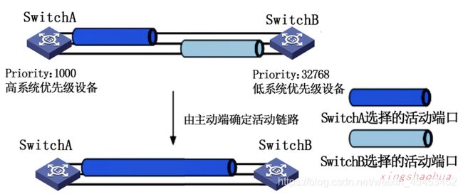
如图所示,Switch A选择上面两个接口为活动接口,而 Switch B选择下面两个接口为活动接口,因为Switch A的优先级比较高。所以最终的活动接口两端都以Switch A为准。因此应首先确定主动端,被动端按照主动端侧的接口优先级来选择活动接口。
6.负载均衡模式
链路聚合的主要作用是提高带宽以及增加冗余,而普遍的做法就是在多条物理链路上实行负载分担、常用的负载分担模式包括:
- dst-ip(目的IP地址)模式:从目的IP地址、出端口的TCP/UDP端口号中分别选择指定位的3bit数值进行异或运算,根据运算结选择Eth - Trunk表中对应的出接口。
- dst-mac(目的MAC地址)模式:从目的MAC地址、VLAN ID、以太网类型及入端口信息中分别选择指定位的3bit数值进行异或运算,根据运算结果选择Eth - Trunk表中对应的出接口。
- src-ip(源IP地址)模式:从源IP地址、入端口的TCP/UDP端口号中分别选择指定位的3bit数值进行异或运算,根据运算结果选择Eth - Trunk表中对应的出接口。
- src-mac(源MAC地址)模式:从源MAC地址、VLAN ID、以太网类型及入端口信息中分别选择指定位的3bit数值进行异或运算,根据运算结果选择Eth - Trunk表中对应的出接口。
- src-dst-ip(源IP地址与目的IP地址的异或)模式:对目的IP地址,源IP地址两种负载分担模式的运算结果进行异或运算,根据运算结果选择Eth-Trunk表中对应的出接口。
- src-dst-mac(源MAC地址与目的MAC地址的异或)模式:从目的MAC地址、源MAC地址、VLAN ID、以太网类型及入端口信息中分别选择指定位的3bit数值进行异或运算,根据运算结果选择Eth-Trunk表中对应的出接口。
二、案例环境
某公司网络拓扑结构如下图所示,其网络架构为接入层以及核心层。接入层二层交换机(S3-S7 )下面接若干个客户端(图中以1台为例),核心交换网络由两台三层交换机(S1、S2 )构成。并通过以太通道提高带宽以及增加冗余。三层方面主要分为两个部分,其中一部分是由OSPF协议构建的网络区域。另一部分是由RIPv2协议构建的网络区域。内网R4下面通过二层交换机连接两个VLAN网络,并通过单臂路由提供VLAN之间的转发,R5连接一台服务器,可供内网、外网同时访问,内网通过R2连接外部网络,外部网络由R1和一台PC7组成。
公司网络设备的三层连接及接口地址如下表所示。

三、需求描述
1.链路聚合
S1和S2使用链路聚合将两条物理线路聚合成一条逻辑线路,用于实现链路负载分担和备份,设置S1为LACP主动端,要求辑链路基于目的MAC的方式进行负载分担。
2.VLAN及VLAN间路由
要求实现所有VLAN客户端和服务器之间的互通。
3.OSPF和RIP部分
R2、R3、S1和S2开启OSPF进程110。所有的设备都属于OSPF区域0。R3、R4和R5开启RIPv2协议,R3的G 0/0/1接口和R4的G 0/ 0/1接口、R4的G 0/0/2接口和R5的G 0/0/2接口都能够收发RIPv2协议报文。
4.路由重分发
要求0SPF环境中所有计算机能够和RIP环境中所有计算机、服务器相互访问。
5.NAT及访问控制
内网环境中所有计算机及服务器除了10.1.21-22.0/24这两个网段外,都可以访问互联网,并通过R2转换为固定IP(202.2.12.100 ),服务器的公网映射地址为202.2.12.200,要求PC7可以通过该地址访问内网服务器。
如果计算机运行实验不流畅,建议不要一次性全部开启设备,先开启一部分设备,配置完毕后,回到用户模式save保存后,关闭设备,再开启另外一些设备。
自行搭建拓扑,那么R1和R2上的互联网接口要通过手动添加模块实现,右击设备图标,在弹出的快捷菜单中选择 “设置” 选项,在弹出的界面中拖拽互联网模块到设备插槽中,如图所示。

(二)、案例实施
一、配置流程
1.配置客户端IP地址
配置PC1-PC7的网络参数,配置方法如下:右击PC设备图标,在弹出的快捷菜单中选择 “设置” 选项,在弹出的界面中单击 “基础配置” 菜单,进入 “基础配置” 界面,在 “基础配置” 界面中填写相关的网络参数即可。IP地址设置如下:
| 设备 | IP地址 | VLAN | 网段 | 网关 |
|---|---|---|---|---|
| PC1 | 10.1.11.100 | 11 | 10.1.11.0/24 | 10.1.11.1 |
| PC2 | 10.1.12.100 | 12 | 10.1.12.0/24 | 10.1.12.1 |
| PC3 | 10.1.13.100 | 13 | 10.1.13.0/24 | 10.1.13.1 |
| PC4 | 10.1.14.100 | 14 | 10.1.14.0/24 | 10.1.14.1 |
| PC5 | 10.1.21.100 | 21 | 10.1.21.0/24 | 10.1.21.1 |
| PC6 | 10.1.22.100 | 22 | 10.1.22.0/24 | 10.1.22.1 |
| PC7 | 202.2.2.100 | — | 202.2.2.0/24 | 202.2.2.1 |
| Server1 | 10.1.100.100 | 100 | 10.1.100.0/24 | 10.1.100.1 |
2.配置链路聚合
华为的链路聚合主要通过LACP实现,在配置时,需要指定优先级、工作模式,负载均衡模式以及所需的成员接口。
S1的配置如下:
The device is running!
system-view
Enter system view, return user view with Ctrl+Z.
[Huawei]sysname S1
[S1]
Jul 18 2020 05:22:04-08:00 S1 DS/4/DATASYNC_CFGCHANGE:OID 1.3.6.1.4.1.2011.5.25.
191.3.1 configurations have been changed. The current change number is 4, the ch
ange loop count is 0, and the maximum number of records is 4095.
[S1]undo info enable						//禁止弹出信息中心,不然弹出的信息报文影响操作
Info: Information center is disabled.
[S1]lacp priority 1000						//配置S1设备的系统LACP优先级
[S1]interface Eth-Trunk 12					//创建链路聚合逻辑接口,名称为Eth-Trunk 12
[S1-Eth-Trunk12]mode lacp-static 			//配置静态LACP模式
[S1-Eth-Trunk12]load-balance dst-mac		//配置负载均衡模式为目标MAC地址
[S1-Eth-Trunk12]trunkport g0/0/11			//添加成员接口g 0/0/11
Info: This operation may take a few seconds. Please wait for a moment...done.
[S1-Eth-Trunk12]trunkport g0/0/12			//添加成员接口g 0/0/12
Info: This operation may take a few seconds. Please wait for a moment...done.
[S1-Eth-Trunk12]quit
[S1]
LACP的优先级值越小,优先级越高,默认情况下,系统LACP优先级为32768,取值范围为0~65535。在两各中选择系统LACP优先级较小的一端作为主动端,如果系统LACP优先级相同,则选择MAC地址较小的一端作为主动端。
S2的配置如下:
The device is running!
system-view
Enter system view, return user view with Ctrl+Z.
[Huawei]sysname S2
[S2]
Jul 18 2020 05:23:52-08:00 S2 DS/4/DATASYNC_CFGCHANGE:OID 1.3.6.1.4.1.2011.5.25.
191.3.1 configurations have been changed. The current change number is 4, the ch
ange loop count is 0, and the maximum number of records is 4095.
[S2]undo info enable
Info: Information center is disabled.
[S2]interface Eth-Trunk 12
[S2-Eth-Trunk12]mode lacp-static
[S2-Eth-Trunk12]trunkport g0/0/11
Info: This operation may take a few seconds. Please wait for a moment...done.
[S2-Eth-Trunk12]trunkport g0/0/12
Info: This operation may take a few seconds. Please wait for a moment...done.
[S2-Eth-Trunk12]quit
[S2]
3.配置VLAN间路由
VLAN之间的路由主要通过S1和S2实现,需要注意的是,即使S1和S2上面的接口都是 Trunk模式,也需要创建相关的VLAN,因为当交换机收到来自某LAN的数据包时,如果它没有该VLAN那么将丢弃数据包。
S1的配置如下:
[S1]vlan batch 11 to 14 1000 to 1002 								//批量创建VLAN-14 VLAN 1000-1002
Info: This operation may take a few seconds. Please wait for a moment...done.
[S1]interface Eth-Trunk 12 											//进入聚合链路接口
[S1-Eth-Trunk12]port link-type trunk 								//配置链路聚合接口模式为Trunk
[S1-Eth-Trunk12]port trunk allow-pass vlan 11 to 14 1000 to 1002 	//Trunk允许VLAN11-14、VLAN1000-1002
[S1-Eth-Trunk12]interface g0/0/21
[S1-GigabitEthernet0/0/21]port link-type trunk 						//链路聚合接口模式为Trunk
[S1-GigabitEthernet0/0/21]port trunk allow-pass vlan all			//允许所有VLAN
[S1-GigabitEthernet0/0/21]int g0/0/22
[S1-GigabitEthernet0/0/22]port link-type trunk
[S1-GigabitEthernet0/0/22]port trunk allow-pass vlan all
[S1-GigabitEthernet0/0/22]int vlanif 11								//进入VLAN 11的虚接口,给VLAN 11设置网关
[S1-Vlanif11]ip address 10.1.11.1 24
[S1-Vlanif11]int vlanif 12
[S1-Vlanif12]ip address 10.1.12.1 24
[S1-Vlanif12]quit
值得注意的是:
华为的Trunk通道默认不允许除 VLAN 1以外的所有VLAN,而 Cisco设备的Trunk链路默认允许所有的VLAN。所以在配置华为设备时,在配置完基本的Trunk配置后,一定要加上允许相关VLAN通过 Trunk的命令。(即Cisco如果接口的链路类型做成了trunk所有的数据都能过去,但是华为和华三恰恰相反,做成trunk后数据过不去,如果想让其过去,必须要写例外。)以允许VLAN 50为例,进入接口模式,执行port trunk allow- pass vlan 50命令;放行所有VLAN,执行port trunk allow-pass vlan all命令。
S2的配置如下:
[S2]vlan batch 11 to 14 1000 to 1002
Info: This operation may take a few seconds. Please wait for a moment...done.
[S2]interface Eth-Trunk 12
[S2-Eth-Trunk12]port link-type trunk
[S2-Eth-Trunk12]port trunk allow-pass vlan all
[S2-Eth-Trunk12]int g0/0/23
[S2-GigabitEthernet0/0/23]port link-type trunk
[S2-GigabitEthernet0/0/23]port trunk allow-pass vlan all
[S2-GigabitEthernet0/0/23]int g0/0/24
[S2-GigabitEthernet0/0/24]port link-type trunk
[S2-GigabitEthernet0/0/24]port trunk allow-pass vlan all
[S2-GigabitEthernet0/0/24]int vlanif 13
[S2-Vlanif13]ip add 10.1.13.1 24
[S2-Vlanif13]int vlanif 14
[S2-Vlanif14]ip add 10.1.14.1 24
[S2-Vlanif14]quit
[S2]
S3的配置如下:
The device is running!
system-view
Enter system view, return user view with Ctrl+Z.
[Huawei]sysname S3
[S3]
Jul 18 2020 05:53:48-08:00 S3 DS/4/DATASYNC_CFGCHANGE:OID 1.3.6.1.4.1.2011.5.25.
191.3.1 configurations have been changed. The current change number is 4, the ch
ange loop count is 0, and the maximum number of records is 4095.
[S3]undo info enable
Info: Information center is disabled.
[S3]vlan batch 11 to 14
Info: This operation may take a few seconds. Please wait for a moment...done.
[S3]int g0/0/1
[S3-GigabitEthernet0/0/1]port link-type trunk
[S3-GigabitEthernet0/0/1]port trunk allow-pass vlan all
[S3-GigabitEthernet0/0/1]int g0/0/2
[S3-GigabitEthernet0/0/2]port link-type access
[S3-GigabitEthernet0/0/2]port default vlan 11
[S3-GigabitEthernet0/0/2]quit
[S3]
S4的配置如下:
The device is running!
system-view
Enter system view, return user view with Ctrl+Z.
[Huawei]sysname S4
[S4]
Jul 18 2020 06:03:24-08:00 S4 DS/4/DATASYNC_CFGCHANGE:OID 1.3.6.1.4.1.2011.5.25.
191.3.1 configurations have been changed. The current change number is 4, the ch
ange loop count is 0, and the maximum number of records is 4095.
[S4]undo info enable
Info: Information center is disabled.
[S4]vlan batch 11 to 14
Info: This operation may take a few seconds. Please wait for a moment...done.
[S4]int g0/0/1
[S4-GigabitEthernet0/0/1]port link-type trunk
[S4-GigabitEthernet0/0/1]port trunk allow-pass vlan all
[S4-GigabitEthernet0/0/1]int g0/0/2
[S4-GigabitEthernet0/0/2]port link-type access
[S4-GigabitEthernet0/0/2]port default vlan 12
[S4-GigabitEthernet0/0/2]quit
[S4]
S5的配置如下:
The device is running!
system-view
Enter system view, return user view with Ctrl+Z.
[Huawei]sysname S5
[S5]
Jul 18 2020 06:09:12-08:00 S5 DS/4/DATASYNC_CFGCHANGE:OID 1.3.6.1.4.1.2011.5.25.
191.3.1 configurations have been changed. The current change number is 4, the ch
ange loop count is 0, and the maximum number of records is 4095.
[S5]undo info enable
Info: Information center is disabled.
[S5]vlan batch 11 to 14
Info: This operation may take a few seconds. Please wait for a moment...done.
[S5]int g0/0/1
[S5-GigabitEthernet0/0/1]port link-type trunk
[S5-GigabitEthernet0/0/1]port trunk allow-pass vlan all
[S5-GigabitEthernet0/0/1]int g0/0/2
[S5-GigabitEthernet0/0/2]port link-type access
[S5-GigabitEthernet0/0/2]port default vlan 13
[S5-GigabitEthernet0/0/2]quit
[S5]
S6的配置如下:
The device is running!
system-view
Enter system view, return user view with Ctrl+Z.
[Huawei]sysname S6
[S6]
Jul 18 2020 06:09:22-08:00 S6 DS/4/DATASYNC_CFGCHANGE:OID 1.3.6.1.4.1.2011.5.25.
191.3.1 configurations have been changed. The current change number is 4, the ch
ange loop count is 0, and the maximum number of records is 4095.
[S6]undo info enable
Info: Information center is disabled.
[S6]vlan batch 11 to 14
Info: This operation may take a few seconds. Please wait for a moment...done.
[S6]int g0/0/1
[S6-GigabitEthernet0/0/1]port link-type trunk
[S6-GigabitEthernet0/0/1]port trunk allow-pass vlan all
[S6-GigabitEthernet0/0/1]int g0/0/2
[S6-GigabitEthernet0/0/2]port link-type access
[S6-GigabitEthernet0/0/2]port default vlan 14
[S6-GigabitEthernet0/0/2]quit
[S6]
4.配置单臂路由
华为的单臂路由配置和Cisco几乎没有差别,主要有两项配置,一项是交换机和路由器Trunk配置,另外一项是路由器的子接口配置及关联相应的VLAN。
R4的配置如下:
The device is running!
system-view
Enter system view, return user view with Ctrl+Z.
[Huawei]sysname R4
[R4]undo info enable
Info: Information center is disabled.
[R4]int g0/0/0.21											//进入子接口
[R4-GigabitEthernet0/0/0.21]ip add 10.1.21.1 24				//配置子接口IP地址
[R4-GigabitEthernet0/0/0.21]dot1q termination vid 21		//子接口和VLAN 21关联
[R4-GigabitEthernet0/0/0.21]arp broadcast enable 			//子接口打开ARP广播
[R4-GigabitEthernet0/0/0.21]int g0/0/0.22
[R4-GigabitEthernet0/0/0.22]ip add 10.1.22.1 24
[R4-GigabitEthernet0/0/0.22]dot1q termination vid 22
[R4-GigabitEthernet0/0/0.22]arp broadcast enable
[R4-GigabitEthernet0/0/0.22]quit
[R4]
S7的配置如下:
The device is running!
system-view
Enter system view, return user view with Ctrl+Z.
[Huawei]sysname S7
[S7]
Jul 18 2020 06:20:52-08:00 S7 DS/4/DATASYNC_CFGCHANGE:OID 1.3.6.1.4.1.2011.5.25.
191.3.1 configurations have been changed. The current change number is 4, the ch
ange loop count is 0, and the maximum number of records is 4095.
[S7]undo info enable
Info: Information center is disabled.
[S7]vlan batch 21 22
Info: This operation may take a few seconds. Please wait for a moment...done.
[S7]int g0/0/3
[S7-GigabitEthernet0/0/3]port link-type trunk
[S7-GigabitEthernet0/0/3]port trunk allow-pass vlan all
[S7-GigabitEthernet0/0/3]int g0/0/1
[S7-GigabitEthernet0/0/1]port link-type access
[S7-GigabitEthernet0/0/1]port default vlan 21
[S7-GigabitEthernet0/0/1]int g0/0/2
[S7-GigabitEthernet0/0/2]port link-type access
[S7-GigabitEthernet0/0/2]port default vlan 22
[S7-GigabitEthernet0/0/2]quit
[S7]
5.配置RIP和OSPF
华为的RIP配置和Cisco命令几乎一致,注意把no变成undo即可。配置OSPF时和Cisco不同,它不是一条network命令同时宣告网络和区域,而是在某个区域下面的子模式宣告相关的网络。
S1的配置如下:
system-view
Enter system view, return user view with Ctrl+Z.
[S1]int g0/0/1
[S1-GigabitEthernet0/0/1]port link-type access
[S1-GigabitEthernet0/0/1]port default vlan 1001				//物理接口加入VLAN 1001
[S1-GigabitEthernet0/0/1]quit
[S1]int vlanif 1000
[S1-Vlanif1000]ip add 10.1.122.11 24
[S1-Vlanif1000]int vlanif 1001								//配置VLAN 1001的虚接口
[S1-Vlanif1001]ip add 10.1.111.11 24
[S1-Vlanif1001]quit
[S1]ospf 110												//进入OSPF进程模式,其中110代表进程ID号
[S1-ospf-110]area 0											//和Cisco不同,华为要先进入某个区域,再network宣告网络
[S1-ospf-110-area-0.0.0.0]network 10.1.111.0 0.0.0.255		//宣告网络,不需要跟区域
[S1-ospf-110-area-0.0.0.0]network 10.1.122.0 0.0.0.255
[S1-ospf-110-area-0.0.0.0]network 10.1.11.0 0.0.0.255
[S1-ospf-110-area-0.0.0.0]network 10.1.12.0 0.0.0.255
[S1-ospf-110-area-0.0.0.0]quit
[S1-ospf-110]quit
[S1]
在配置OSPF时,如果想指定 router-id,可以在进入进程模式时追加router-id,如[S1] ospf 110 router-id 1. 1. 1. 1
另外,华为三层交換机的二层接口没有直接提升为三层接口的命令,类似于Cisco下的no switchport命令。所以在做VLAN间路或者和路由器直连时,只能配置VLAN虚接口。
S2的配置如下:
system-view
Enter system view, return user view with Ctrl+Z.
[S2]int g0/0/2
[S2-GigabitEthernet0/0/2]port link-type access
[S2-GigabitEthernet0/0/2]port default vlan 1002
[S2-GigabitEthernet0/0/2]quit
[S2]int vlanif 1000
[S2-Vlanif1000]ip add 10.1.122.12 24
[S2-Vlanif1000]int vlanif 1002
[S2-Vlanif1002]ip add 10.1.112.12 24
[S2-Vlanif1002]quit
[S2]ospf 110
[S2-ospf-110]area 0
[S2-ospf-110-area-0.0.0.0]networ 10.1.112.0 0.0.0.255
[S2-ospf-110-area-0.0.0.0]networ 10.1.122.0 0.0.0.255
[S2-ospf-110-area-0.0.0.0]networ 10.1.13.0 0.0.0.255
[S2-ospf-110-area-0.0.0.0]networ 10.1.14.0 0.0.0.255
[S2-ospf-110-area-0.0.0.0]quit
[S2-ospf-110]quit
[S2]
R2的配置如下:
The device is running!
system-view
Enter system view, return user view with Ctrl+Z.
[Huawei]sysname R2
[R2]undo info enable
Info: Information center is disabled.
[R2]int g0/0/0
[R2-GigabitEthernet0/0/0]ip add 10.1.113.1 24
[R2-GigabitEthernet0/0/0]undo shutdown
Info: Interface GigabitEthernet0/0/0 is not shutdown.
[R2-GigabitEthernet0/0/0]int g0/0/1
[R2-GigabitEthernet0/0/1]ip add 10.1.111.1 24
[R2-GigabitEthernet0/0/1]undo shutdown
Info: Interface GigabitEthernet0/0/1 is not shutdown.
[R2-GigabitEthernet0/0/1]int g0/0/2
[R2-GigabitEthernet0/0/2]ip add 10.1.112.1 24
[R2-GigabitEthernet0/0/2]undo shutdown
Info: Interface GigabitEthernet0/0/2 is not shutdown.
[R2-GigabitEthernet0/0/2]quit
[R2]ospf 110
[R2-ospf-110]area 0
[R2-ospf-110-area-0.0.0.0]network 10.1.113.0 0.0.0.255
[R2-ospf-110-area-0.0.0.0]network 10.1.111.0 0.0.0.255
[R2-ospf-110-area-0.0.0.0]network 10.1.112.0 0.0.0.255
[R2-ospf-110-area-0.0.0.0]quit
[R2-ospf-110]quit
[R2]
R3的配置如下:
The device is running!
system-view
Enter system view, return user view with Ctrl+Z.
[Huawei]sysname R3
[R3]undo info enable
Info: Information center is disabled.
[R3]int g0/0/0
[R3-GigabitEthernet0/0/0]ip add 10.1.113.3 24
[R3-GigabitEthernet0/0/0]undo shutdown
Info: Interface GigabitEthernet0/0/0 is not shutdown.
[R3-GigabitEthernet0/0/0]int g0/0/1
[R3-GigabitEthernet0/0/1]ip add 10.1.134.3 24
[R3-GigabitEthernet0/0/1]undo shutdown
Info: Interface GigabitEthernet0/0/1 is not shutdown.
[R3-GigabitEthernet0/0/1]quit
[R3]ospf 110
[R3-ospf-110]area 0
[R3-ospf-110-area-0.0.0.0]network 10.1.113.0 0.0.0.255
[R3-ospf-110-area-0.0.0.0]quit
[R3-ospf-110]quit
[R3]rip
[R3-rip-1]version 2			//RIP2是一个无类的路由协议,它使用子网掩码。
[R3-rip-1]undo summary		//不汇总,路由表不自动聚合的
[R3-rip-1]network 10.0.0.0
[R3-rip-1]quit
[R3]
在Cisco的IOS中配置RIP时,既可以通过标准的类宣告网络,也可以根据实际网络来宣告。如接口地址为10.1.1./24,那么在宣告该接口时,命令network 10.1.1.0和命令 network 10.0.0.0都可以,但是 Cisco会自动将其纠正为10.0.0.0(这才是标准的宣告方法)。而在华为中,只能以标准的方式宣告RIP网络,即根据主类的掩码来宣告。
R4的配置如下:
system-view
Enter system view, return user view with Ctrl+Z.
[R4]int g0/0/1
[R4-GigabitEthernet0/0/1]ip add 10.1.134.4 24
[R4-GigabitEthernet0/0/1]undo shutdown
Info: Interface GigabitEthernet0/0/1 is not shutdown.
[R4-GigabitEthernet0/0/1]int g0/0/2
[R4-GigabitEthernet0/0/2]ip add 10.1.145.4 24
[R4-GigabitEthernet0/0/2]undo shutdown
Info: Interface GigabitEthernet0/0/2 is not shutdown.
[R4-GigabitEthernet0/0/2]quit
[R4]rip
[R4-rip-1]version 2
[R4-rip-1]undo summary
[R4-rip-1]network 10.0.0.0
[R4-rip-1]quit
[R4]
R5的配置如下:
The device is running!
system-view
Enter system view, return user view with Ctrl+Z.
[Huawei]sysname R5
[R5]undo info enable
Info: Information center is disabled.
[R5]int g0/0/2
[R5-GigabitEthernet0/0/2]ip add 10.1.145.5 24
[R5-GigabitEthernet0/0/2]undo shutdown
Info: Interface GigabitEthernet0/0/2 is not shutdown.
[R5-GigabitEthernet0/0/2]int g0/0/0
[R5-GigabitEthernet0/0/0]ip add 10.1.100.1 24
[R5-GigabitEthernet0/0/0]undo shutdown
Info: Interface GigabitEthernet0/0/0 is not shutdown.
[R5-GigabitEthernet0/0/0]quit
[R5]rip
[R5-rip-1]version 2
[R5-rip-1]undo summary
[R5-rip-1]network 10.0.0.0
[R5-rip-1]quit
[R5]
6.配置路由重分发
华为的路由重分发是通过import-route命令实现的,不管导入什么协议,都要加上进程ID号。和Cisco一样,如果把A协议导入B协议中,那么首先要进入B的路由进程中,执行导入A的命令。反之同理。
R3的配置如下:
system-view
Enter system view, return user view with Ctrl+Z.
[R3]ospf 110							//进入OSPF进程模式
[R3-ospf-110]import-route rip 1			//将RIP协议重分发到OSPF中,最多15跳
[R3-ospf-110]rip						//进入RIP进程模式
[R3-rip-1]import-route ospf 110			//将OSPF协议重分发到RIP中
[R3-rip-1]quit
[R3]
此时查看路由表
R5上的路由表:
[R5]display ip routing-table
Route Flags: R - relay, D - download to fib
------------------------------------------------------------------------------
Routing Tables: Public
         Destinations : 21       Routes : 21

Destination/Mask    Proto   Pre  Cost      Flags NextHop         Interface

      10.1.11.0/24  RIP     100  2           D   10.1.145.4      GigabitEthernet
0/0/2
      10.1.12.0/24  RIP     100  2           D   10.1.145.4      GigabitEthernet
0/0/2
      10.1.13.0/24  RIP     100  2           D   10.1.145.4      GigabitEthernet
0/0/2
      10.1.14.0/24  RIP     100  2           D   10.1.145.4      GigabitEthernet
0/0/2
      10.1.21.0/24  RIP     100  1           D   10.1.145.4      GigabitEthernet
0/0/2
      10.1.22.0/24  RIP     100  1           D   10.1.145.4      GigabitEthernet
0/0/2
     10.1.100.0/24  Direct  0    0           D   10.1.100.1      GigabitEthernet
0/0/0
     10.1.100.1/32  Direct  0    0           D   127.0.0.1       GigabitEthernet
0/0/0
   10.1.100.255/32  Direct  0    0           D   127.0.0.1       GigabitEthernet
0/0/0
     10.1.111.0/24  RIP     100  2           D   10.1.145.4      GigabitEthernet
0/0/2
     10.1.112.0/24  RIP     100  2           D   10.1.145.4      GigabitEthernet
0/0/2
     10.1.113.0/24  RIP     100  2           D   10.1.145.4      GigabitEthernet
0/0/2
     10.1.122.0/24  RIP     100  2           D   10.1.145.4      GigabitEthernet
0/0/2
     10.1.134.0/24  RIP     100  1           D   10.1.145.4      GigabitEthernet
0/0/2
     10.1.145.0/24  Direct  0    0           D   10.1.145.5      GigabitEthernet
0/0/2
     10.1.145.5/32  Direct  0    0           D   127.0.0.1       GigabitEthernet
0/0/2
   10.1.145.255/32  Direct  0    0           D   127.0.0.1       GigabitEthernet
0/0/2
      127.0.0.0/8   Direct  0    0           D   127.0.0.1       InLoopBack0
      127.0.0.1/32  Direct  0    0           D   127.0.0.1       InLoopBack0
127.255.255.255/32  Direct  0    0           D   127.0.0.1       InLoopBack0
255.255.255.255/32  Direct  0    0           D   127.0.0.1       InLoopBack0

[R5]
S1上的路由表:
[S1]display ip routing-table
Route Flags: R - relay, D - download to fib
------------------------------------------------------------------------------
Routing Tables: Public
         Destinations : 19       Routes : 20

Destination/Mask    Proto   Pre  Cost      Flags NextHop         Interface

      10.1.11.0/24  Direct  0    0           D   10.1.11.1       Vlanif11
      10.1.11.1/32  Direct  0    0           D   127.0.0.1       Vlanif11
      10.1.12.0/24  Direct  0    0           D   10.1.12.1       Vlanif12
      10.1.12.1/32  Direct  0    0           D   127.0.0.1       Vlanif12
      10.1.13.0/24  OSPF    10   2           D   10.1.122.12     Vlanif1000
      10.1.14.0/24  OSPF    10   2           D   10.1.122.12     Vlanif1000
      10.1.21.0/24  O_ASE   150  1           D   10.1.111.1      Vlanif1001
      10.1.22.0/24  O_ASE   150  1           D   10.1.111.1      Vlanif1001
     10.1.100.0/24  O_ASE   150  1           D   10.1.111.1      Vlanif1001
     10.1.111.0/24  Direct  0    0           D   10.1.111.11     Vlanif1001
    10.1.111.11/32  Direct  0    0           D   127.0.0.1       Vlanif1001
     10.1.112.0/24  OSPF    10   2           D   10.1.122.12     Vlanif1000
                    OSPF    10   2           D   10.1.111.1      Vlanif1001
     10.1.113.0/24  OSPF    10   2           D   10.1.111.1      Vlanif1001
     10.1.122.0/24  Direct  0    0           D   10.1.122.11     Vlanif1000
    10.1.122.11/32  Direct  0    0           D   127.0.0.1       Vlanif1000
     10.1.134.0/24  O_ASE   150  1           D   10.1.111.1      Vlanif1001
     10.1.145.0/24  O_ASE   150  1           D   10.1.111.1      Vlanif1001
      127.0.0.0/8   Direct  0    0           D   127.0.0.1       InLoopBack0
      127.0.0.1/32  Direct  0    0           D   127.0.0.1       InLoopBack0

[S1]
此时内网已经全通了,使用PC4测试:
Welcome to use PC Simulator!

PC>ping 10.1.11.100

Ping 10.1.11.100: 32 data bytes, Press Ctrl_C to break
From 10.1.11.100: bytes=32 seq=1 ttl=126 time=156 ms
From 10.1.11.100: bytes=32 seq=2 ttl=126 time=125 ms
From 10.1.11.100: bytes=32 seq=3 ttl=126 time=125 ms
From 10.1.11.100: bytes=32 seq=4 ttl=126 time=94 ms
From 10.1.11.100: bytes=32 seq=5 ttl=126 time=156 ms

--- 10.1.11.100 ping statistics ---
  5 packet(s) transmitted
  5 packet(s) received
  0.00% packet loss
  round-trip min/avg/max = 94/131/156 ms

PC>ping 10.1.12.100

Ping 10.1.12.100: 32 data bytes, Press Ctrl_C to break
From 10.1.12.100: bytes=32 seq=1 ttl=126 time=203 ms
From 10.1.12.100: bytes=32 seq=2 ttl=126 time=109 ms
From 10.1.12.100: bytes=32 seq=3 ttl=126 time=125 ms
From 10.1.12.100: bytes=32 seq=4 ttl=126 time=125 ms
From 10.1.12.100: bytes=32 seq=5 ttl=126 time=110 ms

--- 10.1.12.100 ping statistics ---
  5 packet(s) transmitted
  5 packet(s) received
  0.00% packet loss
  round-trip min/avg/max = 109/134/203 ms

PC>ping 10.1.13.100

Ping 10.1.13.100: 32 data bytes, Press Ctrl_C to break
From 10.1.13.100: bytes=32 seq=1 ttl=127 time=125 ms
From 10.1.13.100: bytes=32 seq=2 ttl=127 time=109 ms
From 10.1.13.100: bytes=32 seq=3 ttl=127 time=78 ms
From 10.1.13.100: bytes=32 seq=4 ttl=127 time=63 ms
From 10.1.13.100: bytes=32 seq=5 ttl=127 time=78 ms

--- 10.1.13.100 ping statistics ---
  5 packet(s) transmitted
  5 packet(s) received
  0.00% packet loss
  round-trip min/avg/max = 63/90/125 ms

PC>ping 10.1.21.100

Ping 10.1.21.100: 32 data bytes, Press Ctrl_C to break
Request timeout!
Request timeout!
From 10.1.21.100: bytes=32 seq=3 ttl=124 time=109 ms
From 10.1.21.100: bytes=32 seq=4 ttl=124 time=125 ms
From 10.1.21.100: bytes=32 seq=5 ttl=124 time=78 ms

--- 10.1.21.100 ping statistics ---
  5 packet(s) transmitted
  3 packet(s) received
  40.00% packet loss
  round-trip min/avg/max = 0/104/125 ms

PC>ping 10.1.22.100

Ping 10.1.22.100: 32 data bytes, Press Ctrl_C to break
Request timeout!
From 10.1.22.100: bytes=32 seq=2 ttl=124 time=94 ms
From 10.1.22.100: bytes=32 seq=3 ttl=124 time=78 ms
From 10.1.22.100: bytes=32 seq=4 ttl=124 time=94 ms
From 10.1.22.100: bytes=32 seq=5 ttl=124 time=109 ms

--- 10.1.22.100 ping statistics ---
  5 packet(s) transmitted
  4 packet(s) received
  20.00% packet loss
  round-trip min/avg/max = 0/93/109 ms

PC>ping 10.1.100.100

Ping 10.1.100.100: 32 data bytes, Press Ctrl_C to break
Request timeout!
Request timeout!
From 10.1.100.100: bytes=32 seq=3 ttl=250 time=78 ms
From 10.1.100.100: bytes=32 seq=4 ttl=250 time=141 ms
From 10.1.100.100: bytes=32 seq=5 ttl=250 time=62 ms

--- 10.1.100.100 ping statistics ---
  5 packet(s) transmitted
  3 packet(s) received
  40.00% packet loss
  round-trip min/avg/max = 0/93/141 ms

PC>
7.配置NAT及访问控制
华为的NAT转换直接配置在外部接口模式下。需要转换的内部流量通过ACL抓取,而转换后的内部全局地址通过配置NAT组实现。
R2的配置如下:
system-view
Enter system view, return user view with Ctrl+Z.
[R2]int g3/0/0
[R2-GigabitEthernet3/0/0]ip add 202.2.12.1 24
[R2-GigabitEthernet3/0/0]quit
[R2]ip route-static 0.0.0.0 0.0.0.0 202.2.12.2//配置静态路由
[R2]ospf 110
[R2-ospf-110]default-route-advertise //向OSPF注入默认路由,即分发路由(前提是自己有默认路由)
[R2-ospf-110]quit
[R2]nat address-group 1 202.2.12.100 202.2.12.100//配置NAT组(池)
[R2]acl 2000//编写编号为2000的ACL
[R2-acl-basic-2000]rule 0 permit source 10.1.0.0 0.0.15.255//规则0,即允许VLAN 11-14可以上网
[R2-acl-basic-2000]rule 10 permit source 10.1.100.0 0.0.0.255//规则10,允许VLAN 100上网
[R2-acl-basic-2000]quit
[R2]int g3/0/0//进入连接外网的接口
[R2-GigabitEthernet3/0/0]nat outbound 2000 address-group 1//NAT转换,2000的ACL
//配置NAT映射,将服务器映射为公网地址202.2.12.200
[R2-GigabitEthernet3/0/0]nat server global 202.2.12.200 inside 10.1.100.100
[R2-GigabitEthernet3/0/0]quit
[R2]acl 3000//配置编号为3000的ACL,禁止VLAN 21-22访问外网
[R2-acl-adv-3000]rule 0 deny ip source 10.1.21.0 0.0.0.255 destination 202.0.0.0 0.255.255.255//规则0
[R2-acl-adv-3000]rule 5 deny ip source 10.1.22.0 0.0.0.255 destination 202.0.0.0 0.255.255.255//规则5
[R2-acl-adv-3000]quit
[R2]int g0/0/0
[R2-GigabitEthernet0/0/0]traffic-filter inbound acl 3000//接口调用ACL 3000
[R2-GigabitEthernet0/0/0]quit
[R2]
华为的ACL和Cisco类似,分为基本和高级,类似于 Cisco的标准和扩展。其中基本的编号为2000~2999,高级的编号为3000~3999。rule后面的编号表示ACL规则的生效顺序。
上述命令中,ACL 2000中标为黑色字体(nat outbound 2000 address-group 1和nat server global 202.2.12.200 inside 10.1.100.100)的规则允许了一个汇总地址是10.1.0.0 /20,而该ACL最终将应用到NAT中,也就意味着ACL 2000中允许的流量将进行NAT转接。实验要求VLAN21、VLAN22以及对应的网段10.1.21.0/24和10.1.22.0 /24不能同互联网。
因为10.1.0.0 /20汇总地址包含了VLAN11、VLAN12、VLAN13、WLAN14,但是不包括VLAN21和VLAN22,所以导致VLAN21和VLAN22发起的流量因为不匹配ACL 2000而不能进行NAT转接,从而导致不能访同互联网。
而ACL 3000也做了明确的限制,国为ACL 3000直接应用在接口上,所以VLAN21和VLAN22的流量匹配拒绝规则直接丢弃。通过这两种方式可以保证VLAN 21和VLAN 22不能访问互联网,生产环境中选择其一即可。而且在访问控制列表规定,不写在列表中的规则,默认为拒绝,故本实验也可以不用编写ACL 3000, 这里只是考虑尽可能多地展示华为命令而已。
R1的配置如下:
The device is running!
system-view
Enter system view, return user view with Ctrl+Z.
[Huawei]sysname R1
[R1]undo info enable
Info: Information center is disabled.
[R1]int g0/0/0
[R1-GigabitEthernet0/0/0]ip add 202.2.12.2 24
[R1-GigabitEthernet0/0/0]undo shutdown
Info: Interface GigabitEthernet0/0/0 is not shutdown.
[R1-GigabitEthernet0/0/0]int g0/0/1
[R1-GigabitEthernet0/0/1]ip add 202.2.2.1 24
[R1-GigabitEthernet0/0/1]undo shutdown
Info: Interface GigabitEthernet0/0/1 is not shutdown.
[R1-GigabitEthernet0/0/1]quit
[R1]
查看内部是否都学习到了默认路由
S1的路由表:
[S1]display ip routing-table
Route Flags: R - relay, D - download to fib
------------------------------------------------------------------------------
Routing Tables: Public
         Destinations : 20       Routes : 21

Destination/Mask    Proto   Pre  Cost      Flags NextHop         Interface

        0.0.0.0/0   O_ASE   150  1           D   10.1.111.1      Vlanif1001
      10.1.11.0/24  Direct  0    0           D   10.1.11.1       Vlanif11
      10.1.11.1/32  Direct  0    0           D   127.0.0.1       Vlanif11
      10.1.12.0/24  Direct  0    0           D   10.1.12.1       Vlanif12
      10.1.12.1/32  Direct  0    0           D   127.0.0.1       Vlanif12
      10.1.13.0/24  OSPF    10   2           D   10.1.122.12     Vlanif1000
      10.1.14.0/24  OSPF    10   2           D   10.1.122.12     Vlanif1000
      10.1.21.0/24  O_ASE   150  1           D   10.1.111.1      Vlanif1001
      10.1.22.0/24  O_ASE   150  1           D   10.1.111.1      Vlanif1001
     10.1.100.0/24  O_ASE   150  1           D   10.1.111.1      Vlanif1001
     10.1.111.0/24  Direct  0    0           D   10.1.111.11     Vlanif1001
    10.1.111.11/32  Direct  0    0           D   127.0.0.1       Vlanif1001
     10.1.112.0/24  OSPF    10   2           D   10.1.122.12     Vlanif1000
                    OSPF    10   2           D   10.1.111.1      Vlanif1001
     10.1.113.0/24  OSPF    10   2           D   10.1.111.1      Vlanif1001
     10.1.122.0/24  Direct  0    0           D   10.1.122.11     Vlanif1000
    10.1.122.11/32  Direct  0    0           D   127.0.0.1       Vlanif1000
     10.1.134.0/24  O_ASE   150  1           D   10.1.111.1      Vlanif1001
     10.1.145.0/24  O_ASE   150  1           D   10.1.111.1      Vlanif1001
      127.0.0.0/8   Direct  0    0           D   127.0.0.1       InLoopBack0
      127.0.0.1/32  Direct  0    0           D   127.0.0.1       InLoopBack0

[S1]
S2的路由表:
[S2]display ip routing-table
Route Flags: R - relay, D - download to fib
------------------------------------------------------------------------------
Routing Tables: Public
         Destinations : 20       Routes : 21

Destination/Mask    Proto   Pre  Cost      Flags NextHop         Interface

        0.0.0.0/0   O_ASE   150  1           D   10.1.112.1      Vlanif1002
      10.1.11.0/24  OSPF    10   2           D   10.1.122.11     Vlanif1000
      10.1.12.0/24  OSPF    10   2           D   10.1.122.11     Vlanif1000
      10.1.13.0/24  Direct  0    0           D   10.1.13.1       Vlanif13
      10.1.13.1/32  Direct  0    0           D   127.0.0.1       Vlanif13
      10.1.14.0/24  Direct  0    0           D   10.1.14.1       Vlanif14
      10.1.14.1/32  Direct  0    0           D   127.0.0.1       Vlanif14
      10.1.21.0/24  O_ASE   150  1           D   10.1.112.1      Vlanif1002
      10.1.22.0/24  O_ASE   150  1           D   10.1.112.1      Vlanif1002
     10.1.100.0/24  O_ASE   150  1           D   10.1.112.1      Vlanif1002
     10.1.111.0/24  OSPF    10   2           D   10.1.112.1      Vlanif1002
                    OSPF    10   2           D   10.1.122.11     Vlanif1000
     10.1.112.0/24  Direct  0    0           D   10.1.112.12     Vlanif1002
    10.1.112.12/32  Direct  0    0           D   127.0.0.1       Vlanif1002
     10.1.113.0/24  OSPF    10   2           D   10.1.112.1      Vlanif1002
     10.1.122.0/24  Direct  0    0           D   10.1.122.12     Vlanif1000
    10.1.122.12/32  Direct  0    0           D   127.0.0.1       Vlanif1000
     10.1.134.0/24  O_ASE   150  1           D   10.1.112.1      Vlanif1002
     10.1.145.0/24  O_ASE   150  1           D   10.1.112.1      Vlanif1002
      127.0.0.0/8   Direct  0    0           D   127.0.0.1       InLoopBack0
      127.0.0.1/32  Direct  0    0           D   127.0.0.1       InLoopBack0

[S2]
R3的路由表:
[R3]display ip routing-table
Route Flags: R - relay, D - download to fib
------------------------------------------------------------------------------
Routing Tables: Public
         Destinations : 22       Routes : 22

Destination/Mask    Proto   Pre  Cost      Flags NextHop         Interface

        0.0.0.0/0   O_ASE   150  1           D   10.1.113.1      GigabitEthernet
0/0/0
      10.1.11.0/24  OSPF    10   3           D   10.1.113.1      GigabitEthernet
0/0/0
      10.1.12.0/24  OSPF    10   3           D   10.1.113.1      GigabitEthernet
0/0/0
      10.1.13.0/24  OSPF    10   3           D   10.1.113.1      GigabitEthernet
0/0/0
      10.1.14.0/24  OSPF    10   3           D   10.1.113.1      GigabitEthernet
0/0/0
      10.1.21.0/24  RIP     100  1           D   10.1.134.4      GigabitEthernet
0/0/1
      10.1.22.0/24  RIP     100  1           D   10.1.134.4      GigabitEthernet
0/0/1
     10.1.100.0/24  RIP     100  2           D   10.1.134.4      GigabitEthernet
0/0/1
     10.1.111.0/24  OSPF    10   2           D   10.1.113.1      GigabitEthernet
0/0/0
     10.1.112.0/24  OSPF    10   2           D   10.1.113.1      GigabitEthernet
0/0/0
     10.1.113.0/24  Direct  0    0           D   10.1.113.3      GigabitEthernet
0/0/0
     10.1.113.3/32  Direct  0    0           D   127.0.0.1       GigabitEthernet
0/0/0
   10.1.113.255/32  Direct  0    0           D   127.0.0.1       GigabitEthernet
0/0/0
     10.1.122.0/24  OSPF    10   3           D   10.1.113.1      GigabitEthernet
0/0/0
     10.1.134.0/24  Direct  0    0           D   10.1.134.3      GigabitEthernet
0/0/1
     10.1.134.3/32  Direct  0    0           D   127.0.0.1       GigabitEthernet
0/0/1
   10.1.134.255/32  Direct  0    0           D   127.0.0.1       GigabitEthernet
0/0/1
     10.1.145.0/24  RIP     100  1           D   10.1.134.4      GigabitEthernet
0/0/1
      127.0.0.0/8   Direct  0    0           D   127.0.0.1       InLoopBack0
      127.0.0.1/32  Direct  0    0           D   127.0.0.1       InLoopBack0
127.255.255.255/32  Direct  0    0           D   127.0.0.1       InLoopBack0
255.255.255.255/32  Direct  0    0           D   127.0.0.1       InLoopBack0

[R3]
R4的路由表:
[R4]display ip routing-table
Route Flags: R - relay, D - download to fib
------------------------------------------------------------------------------
Routing Tables: Public
         Destinations : 25       Routes : 25

Destination/Mask    Proto   Pre  Cost      Flags NextHop         Interface

      10.1.11.0/24  RIP     100  1           D   10.1.134.3      GigabitEthernet
0/0/1
      10.1.12.0/24  RIP     100  1           D   10.1.134.3      GigabitEthernet
0/0/1
      10.1.13.0/24  RIP     100  1           D   10.1.134.3      GigabitEthernet
0/0/1
      10.1.14.0/24  RIP     100  1           D   10.1.134.3      GigabitEthernet
0/0/1
      10.1.21.0/24  Direct  0    0           D   10.1.21.1       GigabitEthernet
0/0/0.21
      10.1.21.1/32  Direct  0    0           D   127.0.0.1       GigabitEthernet
0/0/0.21
    10.1.21.255/32  Direct  0    0           D   127.0.0.1       GigabitEthernet
0/0/0.21
      10.1.22.0/24  Direct  0    0           D   10.1.22.1       GigabitEthernet
0/0/0.22
      10.1.22.1/32  Direct  0    0           D   127.0.0.1       GigabitEthernet
0/0/0.22
    10.1.22.255/32  Direct  0    0           D   127.0.0.1       GigabitEthernet
0/0/0.22
     10.1.100.0/24  RIP     100  1           D   10.1.145.5      GigabitEthernet
0/0/2
     10.1.111.0/24  RIP     100  1           D   10.1.134.3      GigabitEthernet
0/0/1
     10.1.112.0/24  RIP     100  1           D   10.1.134.3      GigabitEthernet
0/0/1
     10.1.113.0/24  RIP     100  1           D   10.1.134.3      GigabitEthernet
0/0/1
     10.1.122.0/24  RIP     100  1           D   10.1.134.3      GigabitEthernet
0/0/1
     10.1.134.0/24  Direct  0    0           D   10.1.134.4      GigabitEthernet
0/0/1
     10.1.134.4/32  Direct  0    0           D   127.0.0.1       GigabitEthernet
0/0/1
   10.1.134.255/32  Direct  0    0           D   127.0.0.1       GigabitEthernet
0/0/1
     10.1.145.0/24  Direct  0    0           D   10.1.145.4      GigabitEthernet
0/0/2
     10.1.145.4/32  Direct  0    0           D   127.0.0.1       GigabitEthernet
0/0/2
   10.1.145.255/32  Direct  0    0           D   127.0.0.1       GigabitEthernet
0/0/2
      127.0.0.0/8   Direct  0    0           D   127.0.0.1       InLoopBack0
      127.0.0.1/32  Direct  0    0           D   127.0.0.1       InLoopBack0
127.255.255.255/32  Direct  0    0           D   127.0.0.1       InLoopBack0
255.255.255.255/32  Direct  0    0           D   127.0.0.1       InLoopBack0

[R4]
R5的路由表:
[R5]display ip routing-table
Route Flags: R - relay, D - download to fib
------------------------------------------------------------------------------
Routing Tables: Public
         Destinations : 21       Routes : 21

Destination/Mask    Proto   Pre  Cost      Flags NextHop         Interface

      10.1.11.0/24  RIP     100  2           D   10.1.145.4      GigabitEthernet
0/0/2
      10.1.12.0/24  RIP     100  2           D   10.1.145.4      GigabitEthernet
0/0/2
      10.1.13.0/24  RIP     100  2           D   10.1.145.4      GigabitEthernet
0/0/2
      10.1.14.0/24  RIP     100  2           D   10.1.145.4      GigabitEthernet
0/0/2
      10.1.21.0/24  RIP     100  1           D   10.1.145.4      GigabitEthernet
0/0/2
      10.1.22.0/24  RIP     100  1           D   10.1.145.4      GigabitEthernet
0/0/2
     10.1.100.0/24  Direct  0    0           D   10.1.100.1      GigabitEthernet
0/0/0
     10.1.100.1/32  Direct  0    0           D   127.0.0.1       GigabitEthernet
0/0/0
   10.1.100.255/32  Direct  0    0           D   127.0.0.1       GigabitEthernet
0/0/0
     10.1.111.0/24  RIP     100  2           D   10.1.145.4      GigabitEthernet
0/0/2
     10.1.112.0/24  RIP     100  2           D   10.1.145.4      GigabitEthernet
0/0/2
     10.1.113.0/24  RIP     100  2           D   10.1.145.4      GigabitEthernet
0/0/2
     10.1.122.0/24  RIP     100  2           D   10.1.145.4      GigabitEthernet
0/0/2
     10.1.134.0/24  RIP     100  1           D   10.1.145.4      GigabitEthernet
0/0/2
     10.1.145.0/24  Direct  0    0           D   10.1.145.5      GigabitEthernet
0/0/2
     10.1.145.5/32  Direct  0    0           D   127.0.0.1       GigabitEthernet
0/0/2
   10.1.145.255/32  Direct  0    0           D   127.0.0.1       GigabitEthernet
0/0/2
      127.0.0.0/8   Direct  0    0           D   127.0.0.1       InLoopBack0
      127.0.0.1/32  Direct  0    0           D   127.0.0.1       InLoopBack0
127.255.255.255/32  Direct  0    0           D   127.0.0.1       InLoopBack0
255.255.255.255/32  Direct  0    0           D   127.0.0.1       InLoopBack0

[R5]
可以看到S1、S2、R3中有默认路由,而R4和R5中没有,也就是默认路由值分发到了OSPF中,而RIP中没有。
8.调整全局路由
RIP区域的计算机若想访问互联网,要有对外的路由,生产环境中一般是生成默认路由。下面尝试在R3的RIP进程中通过命令注入一条默认路由,前提是R3自己要有默认路由。可以在R5上查看路由表,以验证是否存在对外的默认路由。
R3的配置如下:
system-view
Enter system view, return user view with Ctrl+Z.
[R3]rip
[R3-rip-1]default-route originate
[R3-rip-1]quit
[R3]
查看R4的路由表:
[R4]display ip routing-table
Route Flags: R - relay, D - download to fib
------------------------------------------------------------------------------
Routing Tables: Public
         Destinations : 26       Routes : 26

Destination/Mask    Proto   Pre  Cost      Flags NextHop         Interface

        0.0.0.0/0   RIP     100  1           D   10.1.134.3      GigabitEthernet
0/0/1
      10.1.11.0/24  RIP     100  1           D   10.1.134.3      GigabitEthernet
0/0/1
      10.1.12.0/24  RIP     100  1           D   10.1.134.3      GigabitEthernet
0/0/1
      10.1.13.0/24  RIP     100  1           D   10.1.134.3      GigabitEthernet
0/0/1
      10.1.14.0/24  RIP     100  1           D   10.1.134.3      GigabitEthernet
0/0/1
      10.1.21.0/24  Direct  0    0           D   10.1.21.1       GigabitEthernet
0/0/0.21
      10.1.21.1/32  Direct  0    0           D   127.0.0.1       GigabitEthernet
0/0/0.21
    10.1.21.255/32  Direct  0    0           D   127.0.0.1       GigabitEthernet
0/0/0.21
      10.1.22.0/24  Direct  0    0           D   10.1.22.1       GigabitEthernet
0/0/0.22
      10.1.22.1/32  Direct  0    0           D   127.0.0.1       GigabitEthernet
0/0/0.22
    10.1.22.255/32  Direct  0    0           D   127.0.0.1       GigabitEthernet
0/0/0.22
     10.1.100.0/24  RIP     100  1           D   10.1.145.5      GigabitEthernet
0/0/2
     10.1.111.0/24  RIP     100  1           D   10.1.134.3      GigabitEthernet
0/0/1
     10.1.112.0/24  RIP     100  1           D   10.1.134.3      GigabitEthernet
0/0/1
     10.1.113.0/24  RIP     100  1           D   10.1.134.3      GigabitEthernet
0/0/1
     10.1.122.0/24  RIP     100  1           D   10.1.134.3      GigabitEthernet
0/0/1
     10.1.134.0/24  Direct  0    0           D   10.1.134.4      GigabitEthernet
0/0/1
     10.1.134.4/32  Direct  0    0           D   127.0.0.1       GigabitEthernet
0/0/1
   10.1.134.255/32  Direct  0    0           D   127.0.0.1       GigabitEthernet
0/0/1
     10.1.145.0/24  Direct  0    0           D   10.1.145.4      GigabitEthernet
0/0/2
     10.1.145.4/32  Direct  0    0           D   127.0.0.1       GigabitEthernet
0/0/2
   10.1.145.255/32  Direct  0    0           D   127.0.0.1       GigabitEthernet
0/0/2
      127.0.0.0/8   Direct  0    0           D   127.0.0.1       InLoopBack0
      127.0.0.1/32  Direct  0    0           D   127.0.0.1       InLoopBack0
127.255.255.255/32  Direct  0    0           D   127.0.0.1       InLoopBack0
255.255.255.255/32  Direct  0    0           D   127.0.0.1       InLoopBack0

[R4]
查看R5的路由表:
[R5]display ip routing-table
Route Flags: R - relay, D - download to fib
------------------------------------------------------------------------------
Routing Tables: Public
         Destinations : 22       Routes : 22

Destination/Mask    Proto   Pre  Cost      Flags NextHop         Interface

        0.0.0.0/0   RIP     100  2           D   10.1.145.4      GigabitEthernet
0/0/2
      10.1.11.0/24  RIP     100  2           D   10.1.145.4      GigabitEthernet
0/0/2
      10.1.12.0/24  RIP     100  2           D   10.1.145.4      GigabitEthernet
0/0/2
      10.1.13.0/24  RIP     100  2           D   10.1.145.4      GigabitEthernet
0/0/2
      10.1.14.0/24  RIP     100  2           D   10.1.145.4      GigabitEthernet
0/0/2
      10.1.21.0/24  RIP     100  1           D   10.1.145.4      GigabitEthernet
0/0/2
      10.1.22.0/24  RIP     100  1           D   10.1.145.4      GigabitEthernet
0/0/2
     10.1.100.0/24  Direct  0    0           D   10.1.100.1      GigabitEthernet
0/0/0
     10.1.100.1/32  Direct  0    0           D   127.0.0.1       GigabitEthernet
0/0/0
   10.1.100.255/32  Direct  0    0           D   127.0.0.1       GigabitEthernet
0/0/0
     10.1.111.0/24  RIP     100  2           D   10.1.145.4      GigabitEthernet
0/0/2
     10.1.112.0/24  RIP     100  2           D   10.1.145.4      GigabitEthernet
0/0/2
     10.1.113.0/24  RIP     100  2           D   10.1.145.4      GigabitEthernet
0/0/2
     10.1.122.0/24  RIP     100  2           D   10.1.145.4      GigabitEthernet
0/0/2
     10.1.134.0/24  RIP     100  1           D   10.1.145.4      GigabitEthernet
0/0/2
     10.1.145.0/24  Direct  0    0           D   10.1.145.5      GigabitEthernet
0/0/2
     10.1.145.5/32  Direct  0    0           D   127.0.0.1       GigabitEthernet
0/0/2
   10.1.145.255/32  Direct  0    0           D   127.0.0.1       GigabitEthernet
0/0/2
      127.0.0.0/8   Direct  0    0           D   127.0.0.1       InLoopBack0
      127.0.0.1/32  Direct  0    0           D   127.0.0.1       InLoopBack0
127.255.255.255/32  Direct  0    0           D   127.0.0.1       InLoopBack0
255.255.255.255/32  Direct  0    0           D   127.0.0.1       InLoopBack0

[R5]
二、华为的display命令
下面介绍常用的华为display命令,经常使用这些命令可以帮助我们快速获取想要得到的信息,包括查看VLAN、接口状态、指定接口当前的配置信息、NAT转换条目,OSPF邻居信息以及ACL信息等。
1.查看VLAN信息
在Cisco中,如果一个接口配置为Trunk,那么它不属于任何一个VLAN。在华为配置中,如果一个接口配置为Trunk,那么它属于任何一个VLAN,当然这只是从显示效果上来看,其实际的转发原理和Cisco是一致的。
查看S1的VLAN
[S1]display vlan
The total number of vlans is : 8
--------------------------------------------------------------------------------
U: Up;         D: Down;         TG: Tagged;         UT: Untagged;
MP: Vlan-mapping;               ST: Vlan-stacking;
#: ProtocolTransparent-vlan;    *: Management-vlan;
--------------------------------------------------------------------------------

VID  Type    Ports
--------------------------------------------------------------------------------
1    common  UT:GE0/0/2(D)      GE0/0/3(D)      GE0/0/4(D)      GE0/0/5(D)
                GE0/0/6(D)      GE0/0/7(D)      GE0/0/8(D)      GE0/0/9(D)
                GE0/0/10(D)     GE0/0/13(D)     GE0/0/14(D)     GE0/0/15(D)
                GE0/0/16(D)     GE0/0/17(D)     GE0/0/18(D)     GE0/0/19(D)
                GE0/0/20(D)     GE0/0/21(U)     GE0/0/22(U)     GE0/0/23(D)
                GE0/0/24(D)     Eth-Trunk12(U)

11   common  TG:GE0/0/21(U)     GE0/0/22(U)     Eth-Trunk12(U)

12   common  TG:GE0/0/21(U)     GE0/0/22(U)     Eth-Trunk12(U)

13   common  TG:GE0/0/21(U)     GE0/0/22(U)     Eth-Trunk12(U)

14   common  TG:GE0/0/21(U)     GE0/0/22(U)     Eth-Trunk12(U)

1000 common  TG:GE0/0/21(U)     GE0/0/22(U)     Eth-Trunk12(U)

1001 common  UT:GE0/0/1(U)

             TG:GE0/0/21(U)     GE0/0/22(U)     Eth-Trunk12(U)

1002 common  TG:GE0/0/21(U)     GE0/0/22(U)     Eth-Trunk12(U)


VID  Status  Property      MAC-LRN Statistics Description
--------------------------------------------------------------------------------

1    enable  default       enable  disable    VLAN 0001
11   enable  default       enable  disable    VLAN 0011
12   enable  default       enable  disable    VLAN 0012
13   enable  default       enable  disable    VLAN 0013
14   enable  default       enable  disable    VLAN 0014
1000 enable  default       enable  disable    VLAN 1000
1001 enable  default       enable  disable    VLAN 1001
1002 enable  default       enable  disable    VLAN 1002
[S1]
2.查看接口状态
查看S1的接口状态:
[S1]display ip interface brief
*down: administratively down
^down: standby
(l): loopback
(s): spoofing
The number of interface that is UP in Physical is 6
The number of interface that is DOWN in Physical is 1
The number of interface that is UP in Protocol is 5
The number of interface that is DOWN in Protocol is 2

Interface                         IP Address/Mask      Physical   Protocol
MEth0/0/1                         unassigned           down       down
NULL0                             unassigned           up         up(s)
Vlanif1                           unassigned           up         down
Vlanif11                          10.1.11.1/24         up         up
Vlanif12                          10.1.12.1/24         up         up
Vlanif1000                        10.1.122.11/24       up         up
Vlanif1001                        10.1.111.11/24       up         up
[S1]
华为的虚接口名称以Vlanif开头,它是 Vlan Interface的缩写。
Cisco查看接口状态的命令为show ip interface brief
3.查看某一个接口的当前配置信息
为了可以更加精确地定位到某一个接口的配置,而不是从众多配置信息中查找,华为提供了类似Cisco中的show run interface f0/0的命令。
查看S1的接口:
[S1]display current-configuration interface vlan 1000
#
interface Vlanif1000
 ip address 10.1.122.11 255.255.255.0
#
return
[S1]display current-configuration interface GigabitEthernet 0/0/1
#
interface GigabitEthernet0/0/1
 port link-type access
 port default vlan 1001
#
return
[S1]display current-configuration interface GigabitEthernet 0/0/2
#
interface GigabitEthernet0/0/2
#
return
[S1]display this			//显示当前视图运行的配置
#
sysname S1
#
undo info-center enable
#
vlan batch 11 to 14 1000 to 1002
#
lacp priority 1000
#
cluster enable
ntdp enable
ndp enable
#
drop illegal-mac alarm
#
return
[S1]
4.查看NAT转换条目
华为的NAT转换条目每一个报文都会产生一个转换项,重点关注 SrcAddr→New SrcAddr或者DestAddr→New DestAddr,以了解转换关系。
(1)内网访问外网:
PC1 ping PC7:
PC>ping 202.2.2.100

Ping 202.2.2.100: 32 data bytes, Press Ctrl_C to break
From 202.2.2.100: bytes=32 seq=1 ttl=125 time=62 ms
From 202.2.2.100: bytes=32 seq=2 ttl=125 time=78 ms
From 202.2.2.100: bytes=32 seq=3 ttl=125 time=47 ms
From 202.2.2.100: bytes=32 seq=4 ttl=125 time=63 ms
From 202.2.2.100: bytes=32 seq=5 ttl=125 time=62 ms

--- 202.2.2.100 ping statistics ---
  5 packet(s) transmitted
  5 packet(s) received
  0.00% packet loss
  round-trip min/avg/max = 47/62/78 ms

PC>
R2上的NAT转换条目:
[R2]display nat session all
  NAT Session Table Information:

     Protocol          : ICMP(1)
     SrcAddr   Vpn     : 10.1.11.100
     DestAddr  Vpn     : 202.2.2.100
     Type Code IcmpId  : 0   8   29903
     NAT-Info
       New SrcAddr     : 202.2.12.100
       New DestAddr    : ----
       New IcmpId      : 10240

     Protocol          : ICMP(1)
     SrcAddr   Vpn     : 10.1.11.100
     DestAddr  Vpn     : 202.2.2.100
     Type Code IcmpId  : 0   8   29905
     NAT-Info
       New SrcAddr     : 202.2.12.100
       New DestAddr    : ----
       New IcmpId      : 10241

     Protocol          : ICMP(1)
     SrcAddr   Vpn     : 10.1.11.100
     DestAddr  Vpn     : 202.2.2.100
     Type Code IcmpId  : 0   8   29907
     NAT-Info
       New SrcAddr     : 202.2.12.100
       New DestAddr    : ----
       New IcmpId      : 10242

     Protocol          : ICMP(1)
     SrcAddr   Vpn     : 10.1.11.100
     DestAddr  Vpn     : 202.2.2.100
     Type Code IcmpId  : 0   8   29909
     NAT-Info
       New SrcAddr     : 202.2.12.100
       New DestAddr    : ----
       New IcmpId      : 10243

     Protocol          : ICMP(1)
     SrcAddr   Vpn     : 10.1.11.100
     DestAddr  Vpn     : 202.2.2.100
     Type Code IcmpId  : 0   8   29910
     NAT-Info
       New SrcAddr     : 202.2.12.100
       New DestAddr    : ----
       New IcmpId      : 10244

  Total : 5
[R2]
(2)外网访问内网:
PC7 ping Server1:注意此时外网访问内网,应使用的是NAT转换的IP地址202.2.12.200
PC>ping 202.2.12.200

Ping 202.2.12.200: 32 data bytes, Press Ctrl_C to break
From 202.2.12.200: bytes=32 seq=1 ttl=250 time=32 ms
From 202.2.12.200: bytes=32 seq=2 ttl=250 time=31 ms
From 202.2.12.200: bytes=32 seq=3 ttl=250 time=31 ms
From 202.2.12.200: bytes=32 seq=4 ttl=250 time=31 ms
From 202.2.12.200: bytes=32 seq=5 ttl=250 time=32 ms

--- 202.2.12.200 ping statistics ---
  5 packet(s) transmitted
  5 packet(s) received
  0.00% packet loss
  round-trip min/avg/max = 31/31/32 ms

PC>
R2上的NAT转换条目:
[R2]display nat session all
  NAT Session Table Information:

     Protocol          : ICMP(1)
     SrcAddr   Vpn     : 202.2.2.100
     DestAddr  Vpn     : 202.2.12.200
     Type Code IcmpId  : 0   8   30905
     NAT-Info
       New SrcAddr     : ----
       New DestAddr    : 10.1.100.100
       New IcmpId      : ----

     Protocol          : ICMP(1)
     SrcAddr   Vpn     : 202.2.2.100
     DestAddr  Vpn     : 202.2.12.200
     Type Code IcmpId  : 0   8   30908
     NAT-Info
       New SrcAddr     : ----
       New DestAddr    : 10.1.100.100
       New IcmpId      : ----

     Protocol          : ICMP(1)
     SrcAddr   Vpn     : 202.2.2.100
     DestAddr  Vpn     : 202.2.12.200
     Type Code IcmpId  : 0   8   30904
     NAT-Info
       New SrcAddr     : ----
       New DestAddr    : 10.1.100.100
       New IcmpId      : ----

     Protocol          : ICMP(1)
     SrcAddr   Vpn     : 202.2.2.100
     DestAddr  Vpn     : 202.2.12.200
     Type Code IcmpId  : 0   8   30907
     NAT-Info
       New SrcAddr     : ----
       New DestAddr    : 10.1.100.100
       New IcmpId      : ----

     Protocol          : ICMP(1)
     SrcAddr   Vpn     : 202.2.2.100
     DestAddr  Vpn     : 202.2.12.200
     Type Code IcmpId  : 0   8   30906
     NAT-Info
       New SrcAddr     : ----
       New DestAddr    : 10.1.100.100
       New IcmpId      : ----

  Total : 5
[R2]
Cisco使用show ip nat transation命令。
5.查看OSPF邻居信息
华为的OSPF邻居最终状态也是full状态。同时华为也提供了类似Cisco中的show ip ospf neighbor的命令。华为查看OSPF邻居的命令如下:
查看S1的OSPF邻居:
[S1]display ospf peer brief

	 OSPF Process 110 with Router ID 10.1.11.1
		  Peer Statistic Information
 ----------------------------------------------------------------------------
 Area Id          Interface                        Neighbor id      State
 0.0.0.0          Vlanif1000                       10.1.13.1        Full
 0.0.0.0          Vlanif1001                       10.1.113.1       Full
 ----------------------------------------------------------------------------
[S1]
6.查看ACL信息
查看R2的ACL信息:
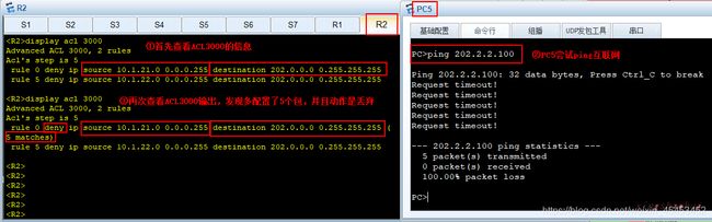
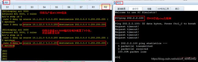
[R2]display acl all
 Total quantity of nonempty ACL number is 2

Basic ACL 2000, 2 rules
Acl's step is 5
 rule 0 permit source 10.1.0.0 0.0.15.255
 rule 10 permit source 10.1.100.0 0.0.0.255

Advanced ACL 3000, 2 rules
Acl's step is 5
 rule 0 deny ip source 10.1.21.0 0.0.0.255 destination 202.0.0.0 0.255.255.255
 rule 5 deny ip source 10.1.22.0 0.0.0.255 destination 202.0.0.0 0.255.255.255

[R2]
对应的Cisco命令为show access list
三、实验结果验证
完成上述实验步骤后,可以从以下几个方面进行验证:
1.验证以太通道配置
在S1上查看:
[S1]display eth-trunk 12
Eth-Trunk12's state information is:
Local:
LAG ID: 12                  WorkingMode: STATIC
Preempt Delay: Disabled     Hash arithmetic: According to DA
System Priority: 1000       System ID: 4c1f-ccbf-5f02
Least Active-linknumber: 1  Max Active-linknumber: 8
Operate status: up          Number Of Up Port In Trunk: 2
--------------------------------------------------------------------------------
ActorPortName          Status   PortType PortPri PortNo PortKey PortState Weight
GigabitEthernet0/0/11  Selected 1GE      32768   12     3121    10111100  1
GigabitEthernet0/0/12  Selected 1GE      32768   13     3121    10111100  1

Partner:
--------------------------------------------------------------------------------
ActorPortName          SysPri   SystemID        PortPri PortNo PortKey PortState
GigabitEthernet0/0/11  32768    4c1f-cc2c-138d  32768   12     3121    10111100
GigabitEthernet0/0/12  32768    4c1f-cc2c-138d  32768   13     3121    10111100

[S1]
2.验证VLAN间路由
在PC1上尝试ping内网所有的VLAN均可以通信。
PC>ping 10.1.12.100

Ping 10.1.12.100: 32 data bytes, Press Ctrl_C to break
From 10.1.12.100: bytes=32 seq=1 ttl=127 time=78 ms
From 10.1.12.100: bytes=32 seq=2 ttl=127 time=94 ms
From 10.1.12.100: bytes=32 seq=3 ttl=127 time=93 ms
From 10.1.12.100: bytes=32 seq=4 ttl=127 time=78 ms
From 10.1.12.100: bytes=32 seq=5 ttl=127 time=94 ms

--- 10.1.12.100 ping statistics ---
  5 packet(s) transmitted
  5 packet(s) received
  0.00% packet loss
  round-trip min/avg/max = 78/87/94 ms

PC>ping 10.1.13.100

Ping 10.1.13.100: 32 data bytes, Press Ctrl_C to break
From 10.1.13.100: bytes=32 seq=1 ttl=126 time=94 ms
From 10.1.13.100: bytes=32 seq=2 ttl=126 time=93 ms
From 10.1.13.100: bytes=32 seq=3 ttl=126 time=109 ms
From 10.1.13.100: bytes=32 seq=4 ttl=126 time=110 ms
From 10.1.13.100: bytes=32 seq=5 ttl=126 time=79 ms

--- 10.1.13.100 ping statistics ---
  5 packet(s) transmitted
  5 packet(s) received
  0.00% packet loss
  round-trip min/avg/max = 79/97/110 ms

PC>ping 10.1.14.100

Ping 10.1.14.100: 32 data bytes, Press Ctrl_C to break
From 10.1.14.100: bytes=32 seq=1 ttl=126 time=109 ms
From 10.1.14.100: bytes=32 seq=2 ttl=126 time=109 ms
From 10.1.14.100: bytes=32 seq=3 ttl=126 time=110 ms
From 10.1.14.100: bytes=32 seq=4 ttl=126 time=140 ms
From 10.1.14.100: bytes=32 seq=5 ttl=126 time=110 ms

--- 10.1.14.100 ping statistics ---
  5 packet(s) transmitted
  5 packet(s) received
  0.00% packet loss
  round-trip min/avg/max = 109/115/140 ms

PC>ping 10.1.21.100

Ping 10.1.21.100: 32 data bytes, Press Ctrl_C to break
Request timeout!
From 10.1.21.100: bytes=32 seq=2 ttl=124 time=94 ms
From 10.1.21.100: bytes=32 seq=3 ttl=124 time=109 ms
From 10.1.21.100: bytes=32 seq=4 ttl=124 time=78 ms
From 10.1.21.100: bytes=32 seq=5 ttl=124 time=110 ms

--- 10.1.21.100 ping statistics ---
  5 packet(s) transmitted
  4 packet(s) received
  20.00% packet loss
  round-trip min/avg/max = 0/97/110 ms

PC>ping 10.1.22.100

Ping 10.1.22.100: 32 data bytes, Press Ctrl_C to break
Request timeout!
From 10.1.22.100: bytes=32 seq=2 ttl=124 time=78 ms
From 10.1.22.100: bytes=32 seq=3 ttl=124 time=94 ms
From 10.1.22.100: bytes=32 seq=4 ttl=124 time=93 ms
From 10.1.22.100: bytes=32 seq=5 ttl=124 time=63 ms

--- 10.1.22.100 ping statistics ---
  5 packet(s) transmitted
  4 packet(s) received
  20.00% packet loss
  round-trip min/avg/max = 0/82/94 ms

PC>ping 10.1.100.100

Ping 10.1.100.100: 32 data bytes, Press Ctrl_C to break
From 10.1.100.100: bytes=32 seq=1 ttl=250 time=78 ms
From 10.1.100.100: bytes=32 seq=2 ttl=250 time=94 ms
From 10.1.100.100: bytes=32 seq=3 ttl=250 time=187 ms
From 10.1.100.100: bytes=32 seq=4 ttl=250 time=47 ms
From 10.1.100.100: bytes=32 seq=5 ttl=250 time=93 ms

--- 10.1.100.100 ping statistics ---
  5 packet(s) transmitted
  5 packet(s) received
  0.00% packet loss
  round-trip min/avg/max = 47/99/187 ms

PC>
3.验证RIP和OSPF
在R3上,既可以看到OSPF学习到的路由,也可以看到RIP学习的路由。
[R3]display ip routing-table
Route Flags: R - relay, D - download to fib
------------------------------------------------------------------------------
Routing Tables: Public
         Destinations : 22       Routes : 22

Destination/Mask    Proto   Pre  Cost      Flags NextHop         Interface

        0.0.0.0/0   O_ASE   150  1           D   10.1.113.1      GigabitEthernet
0/0/0
      10.1.11.0/24  OSPF    10   3           D   10.1.113.1      GigabitEthernet
0/0/0
      10.1.12.0/24  OSPF    10   3           D   10.1.113.1      GigabitEthernet
0/0/0
      10.1.13.0/24  OSPF    10   3           D   10.1.113.1      GigabitEthernet
0/0/0
      10.1.14.0/24  OSPF    10   3           D   10.1.113.1      GigabitEthernet
0/0/0
      10.1.21.0/24  RIP     100  1           D   10.1.134.4      GigabitEthernet
0/0/1
      10.1.22.0/24  RIP     100  1           D   10.1.134.4      GigabitEthernet
0/0/1
     10.1.100.0/24  RIP     100  2           D   10.1.134.4      GigabitEthernet
0/0/1
     10.1.111.0/24  OSPF    10   2           D   10.1.113.1      GigabitEthernet
0/0/0
     10.1.112.0/24  OSPF    10   2           D   10.1.113.1      GigabitEthernet
0/0/0
     10.1.113.0/24  Direct  0    0           D   10.1.113.3      GigabitEthernet
0/0/0
     10.1.113.3/32  Direct  0    0           D   127.0.0.1       GigabitEthernet
0/0/0
   10.1.113.255/32  Direct  0    0           D   127.0.0.1       GigabitEthernet
0/0/0
     10.1.122.0/24  OSPF    10   3           D   10.1.113.1      GigabitEthernet
0/0/0
     10.1.134.0/24  Direct  0    0           D   10.1.134.3      GigabitEthernet
0/0/1
     10.1.134.3/32  Direct  0    0           D   127.0.0.1       GigabitEthernet
0/0/1
   10.1.134.255/32  Direct  0    0           D   127.0.0.1       GigabitEthernet
0/0/1
     10.1.145.0/24  RIP     100  1           D   10.1.134.4      GigabitEthernet
0/0/1
      127.0.0.0/8   Direct  0    0           D   127.0.0.1       InLoopBack0
      127.0.0.1/32  Direct  0    0           D   127.0.0.1       InLoopBack0
127.255.255.255/32  Direct  0    0           D   127.0.0.1       InLoopBack0
255.255.255.255/32  Direct  0    0           D   127.0.0.1       InLoopBack0

[R3]
4.验证重分发
在R3上执行重分发后,应该可以在R2上学习到RIP区域的路由,也可以在R5上学习到OSPF区域的路信息。
R2上的路由重分发:
[R2]display ospf routing

	 OSPF Process 110 with Router ID 10.1.113.1
		  Routing Tables

 Routing for Network
 Destination        Cost  Type       NextHop         AdvRouter       Area
 10.1.111.0/24      1     Transit    10.1.111.1      10.1.113.1      0.0.0.0
 10.1.112.0/24      1     Transit    10.1.112.1      10.1.113.1      0.0.0.0
 10.1.113.0/24      1     Transit    10.1.113.1      10.1.113.1      0.0.0.0
 10.1.11.0/24       2     Stub       10.1.111.11     10.1.11.1       0.0.0.0
 10.1.12.0/24       2     Stub       10.1.111.11     10.1.11.1       0.0.0.0
 10.1.13.0/24       2     Stub       10.1.112.12     10.1.13.1       0.0.0.0
 10.1.14.0/24       2     Stub       10.1.112.12     10.1.13.1       0.0.0.0
 10.1.122.0/24      2     Transit    10.1.112.12     10.1.11.1       0.0.0.0
 10.1.122.0/24      2     Transit    10.1.111.11     10.1.11.1       0.0.0.0

 Routing for ASEs
 Destination        Cost      Type       Tag         NextHop         AdvRouter
 10.1.21.0/24       1         Type2      1           10.1.113.3      10.1.113.3
 10.1.22.0/24       1         Type2      1           10.1.113.3      10.1.113.3
 10.1.100.0/24      1         Type2      1           10.1.113.3      10.1.113.3
 10.1.134.0/24      1         Type2      1           10.1.113.3      10.1.113.3
 10.1.145.0/24      1         Type2      1           10.1.113.3      10.1.113.3

 Total Nets: 14
 Intra Area: 9  Inter Area: 0  ASE: 5  NSSA: 0

[R2]

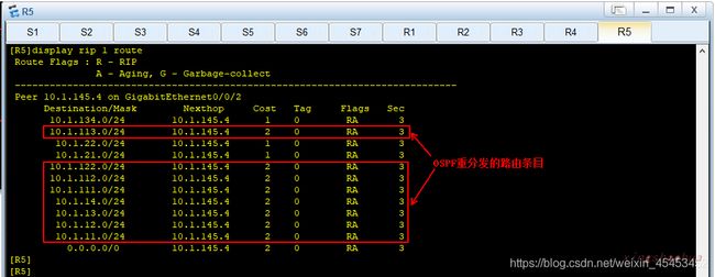
R5上的路由重分发:
[R5]display rip 1 route
 Route Flags : R - RIP
               A - Aging, G - Garbage-collect
 ----------------------------------------------------------------------------
 Peer 10.1.145.4 on GigabitEthernet0/0/2
      Destination/Mask        Nexthop     Cost   Tag     Flags   Sec
       10.1.134.0/24        10.1.145.4      1    0        RA       3
       10.1.113.0/24        10.1.145.4      2    0        RA       3
        10.1.22.0/24        10.1.145.4      1    0        RA       3
        10.1.21.0/24        10.1.145.4      1    0        RA       3
       10.1.122.0/24        10.1.145.4      2    0        RA       3
       10.1.112.0/24        10.1.145.4      2    0        RA       3
       10.1.111.0/24        10.1.145.4      2    0        RA       3
        10.1.14.0/24        10.1.145.4      2    0        RA       3
        10.1.13.0/24        10.1.145.4      2    0        RA       3
        10.1.12.0/24        10.1.145.4      2    0        RA       3
        10.1.11.0/24        10.1.145.4      2    0        RA       3
          0.0.0.0/0         10.1.145.4      2    0        RA       3
[R5]
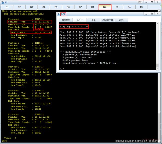
5.验证NAT转换
在PC1上尝试ping互联网,然后在R2上查看转换条目.可以看到源地址10.1.11.100转换为202.2.12.100。如图所示。
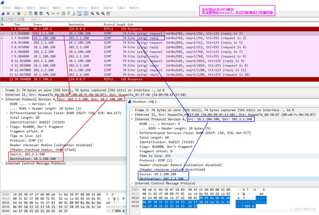
在PC7上尝试ping服务器映射后的地址202.2.12.200,在R5 和 Server1之间抓包可以抓到该流量,说明该流量到达R2之后,被重定向到内部服务器,如图所示。

6.验证PC5不能访问互联网
实验目标是VLAN21 和VLAN22 不能访问互联网。在本案例中,不管是通过在应用NAT的ACL 2000上排除网段,还是在ACL 3000中拒绝流量都可以实现这个目标,结果如图所示。
PC5(VLAN21)尝试访问外网:
PC6(VLAN22)尝试访问外网:
这只是我的一些浅薄的见解,望多指教!