2、单目相机外参标定(camera_calibration_external)
*外参标定即为相机坐标系和系统世界坐标系关系的旋转和平移矩阵;可以简化理解为一个3*3的矩阵
ImgPath := '3d_machine_vision/calib/'
dev_close_window ()
dev_open_window (0, 0, 652, 494, 'black', WindowHandle)
dev_update_off ()
dev_set_draw ('margin')
dev_set_line_width (1)
set_display_font (WindowHandle, 14, 'courier', 'true', 'false')
* Read the internal camera parameters from file
*读取刚刚得到的相机内参;ps:外参标定必须先标定好相机的内参
read_cam_par ('camera_parameters.dat', CamParam)
*
* Determine the external camera parameters and world coodinates from image points
*
*这个外参相机参数能通过图像来获得,如果这个标定板直接放置下测量平面上的话
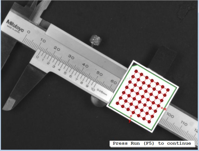
* The external camera parameters can be determined from an image, where the
* calibration plate is positioned directly on the measurement plane
read_image (Image, ImgPath + 'calib_11')
dev_display (Image)
CaltabName := 'caltab_30mm.descr'
create_calib_data ('calibration_object', 1, 1, CalibDataID)
* Here, the final camera parameters are already known and can be used instead
* of the starting values used in the program 'camera_calibration_internal.hdev'
set_calib_data_cam_param (CalibDataID, 0, 'area_scan_division', CamParam)
set_calib_data_calib_object (CalibDataID, 0, CaltabName)
find_calib_object (Image, CalibDataID, 0, 0, 1, [], [])
get_calib_data_observ_contours (Caltab, CalibDataID, 'caltab', 0, 0, 1)
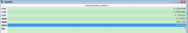 PoseForCalibrationPlate(这个表示这张图片中相机对应的相机外参为多少)
get_calib_data_observ_points (CalibDataID, 0, 0, 1, RCoord, CCoord, Index, PoseForCalibrationPlate)
dev_set_color ('green')
dev_display (Caltab)
dev_set_color ('red')
disp_caltab (WindowHandle, CaltabName, CamParam, PoseForCalibrationPlate, 1)
dev_set_line_width (3)
disp_circle (WindowHandle, RCoord, CCoord, gen_tuple_const(|RCoord|,1.5))
* caltab_points (CaltabName, X, Y, Z)
* calibrate_cameras (CalibDataID, Error)
* To take the thickness of the calibration plate into account, the z-value
* of the origin given by the camera pose has to be translated by the
* thickness of the calibration plate.
* Deactivate the following line if you do not want to add the correction.
*加上标定板的厚度(0.00075)得到最终的该标定板下的相机参数
set_origin_pose (PoseForCalibrationPlate, 0, 0, 0.00075, PoseForCalibrationPlate)
disp_continue_message (WindowHandle, 'black', 'true')
stop ()
* Alternatively, the external camera parameters can be determined from
* at least three point correspondances between the WCS and the pixel coordinate system
read_image (Image, ImgPath + 'caliper_01')
dev_display (Image)
* Set the world coordinates of three points on the rule
X := [0,50,100,80]
Y := [5,0,5,0]
Z := [0,0,0,0]
* Set the respective image plane coordinates of the three points
RCoord := [414,227,85,128]
CCoord := [119,318,550,448]
*
disp_cross (WindowHandle, RCoord, CCoord, 6, 0)
*利用vector_to_pose求得FinalPose
vector_to_pose (X, Y, Z, RCoord, CCoord, CamParam, 'iterative', 'error', FinalPose, Errors)
write_pose (FinalPose, 'pose_from_three_points.dat')
* Now, transform a point measured interactively into the WCS
dev_update_window ('on')
dev_display (Image)
while (1)
disp_message (WindowHandle, 'Measure one point: left mouse button', 'window', 12, 12, 'red', 'false')
disp_message (WindowHandle, 'Exit measure mode: right mouse button', 'window', 36, 12, 'red', 'false')
get_mbutton (WindowHandle, Row, Column, Button)
if (Button == 4)
break
endif
dev_display (Image)
dev_set_color ('green')
disp_cross (WindowHandle, Row, Column, 6, 0)
image_points_to_world_plane (CamParam, FinalPose, Row, Column, 1, X1, Y1)
disp_message (WindowHandle, 'X = ' + X1, 'window', 320, 400, 'red', 'false')
disp_message (WindowHandle, 'Y = ' + Y1, 'window', 340, 400, 'red', 'false')
endwhile
*建立一个测量工具进行世界坐标的标定测量
* Apply the measure tool and transform the resulting point coordinates
* into the WCS
dev_set_color ('red')
dev_display (Image)
* Set the world coordinates of four points defining a ROI for the measure tool
*设置区域(世界坐标的区域)
ROI_X_WCS := [-2,-2,112,112]
ROI_Y_WCS := [0,0.5,0.5,0]
ROI_Z_WCS := [0,0,0,0]
* Determine the transformation matrix from the WCS into the CCS
*转换PS:这个转换以后会常用到
pose_to_hom_mat3d (FinalPose, CCS_HomMat_WCS)
* Transform the point coordintes into the image coordinate system
*转换成图像坐标的参数roi,CCS_HomMat_WCS(4*4矩阵),转换成CCS的坐标转换中心
affine_trans_point_3d (CCS_HomMat_WCS, ROI_X_WCS, ROI_Y_WCS, ROI_Z_WCS, CCS_RectangleX, CCS_RectangleY, CCS_RectangleZ)
*通过相机内参转换成图像坐标
project_3d_point (CCS_RectangleX, CCS_RectangleY, CCS_RectangleZ, CamParam, RectangleRow, RectangleCol)
gen_region_polygon_filled (ROI, RectangleRow, RectangleCol)
smallest_rectangle2 (ROI, RowCenterROI, ColCenterROI, PhiROI, Length1ROI, Length2ROI)
* Create a measure
gen_measure_rectangle2 (RowCenterROI, ColCenterROI, PhiROI, Length1ROI, Length2ROI, 652, 494, 'bilinear', MeasureHandle)
measure_pairs (Image, MeasureHandle, 0.4, 5, 'all_strongest', 'all', RowEdgeFirst, ColumnEdgeFirst, AmplitudeFirst, RowEdgeSecond, ColumnEdgeSecond, AmplitudeSecond, IntraDistance, InterDistance)
close_measure (MeasureHandle)
dev_display (Image)
disp_message (WindowHandle, 'Measuring the position of the pitch lines', 'window', 450, 25, 'red', 'false')
dev_set_color ('green')
RowPitchLine := (RowEdgeFirst + RowEdgeSecond) / 2.0
ColPitchLine := (ColumnEdgeFirst + ColumnEdgeSecond) / 2.0
disp_cross (WindowHandle, RowPitchLine, ColPitchLine, 6, 0)
image_points_to_world_plane (CamParam, FinalPose, RowPitchLine, ColPitchLine, 1, X1, Y1)
for i := 1 to |X1| by 1
set_tposition (WindowHandle, RowEdgeFirst[i - 1] + 5, ColumnEdgeFirst[i - 1] - 20)
if (i == |X1|)
set_tposition (WindowHandle, RowEdgeFirst[i - 1], ColumnEdgeFirst[i - 2])
endif
write_string (WindowHandle, X1[i - 1]$'.3f' + 'mm')
endfor
disp_continue_message (WindowHandle, 'black', 'true')
stop ()
dev_display (Image)
* Apply a line extraction and transform the resulting XLD contours
* into the WCS
* Set the world coordinates of four points defining a ROI
ROI_X_WCS := [11,11,13,13]
ROI_Y_WCS := [4,6,6,4]
ROI_Z_WCS := [0,0,0,0]
* Transform the point coordinates into the image coordinate system
affine_trans_point_3d (CCS_HomMat_WCS, ROI_X_WCS, ROI_Y_WCS, ROI_Z_WCS, CCS_RectangleX, CCS_RectangleY, CCS_RectangleZ)
project_3d_point (CCS_RectangleX, CCS_RectangleY, CCS_RectangleZ, CamParam, RectangleRow, RectangleCol)
* Visualize the square in the original image
disp_polygon (WindowHandle, [RectangleRow,RectangleRow[0]], [RectangleCol,RectangleCol[0]])
dev_display (Image)
* create the ROI
gen_region_polygon_filled (ROI, RectangleRow, RectangleCol)
reduce_domain (Image, ROI, ImageReduced)
* Extract the lines
lines_gauss (ImageReduced, Lines, 1, 3, 8, 'dark', 'true', 'bar-shaped', 'true')
* Adapt the pose of the measurement plane to the tilted plane of the vernier
RelPose := [0,3.2,0,-14,0,0,0]
pose_to_hom_mat3d (FinalPose, HomMat3D)
pose_to_hom_mat3d (RelPose, HomMat3DRel)
hom_mat3d_compose (HomMat3D, HomMat3DRel, HomMat3DAdapted)
* Alternatively, the adaption can be done using the operators
* hom_mat3d_translate_local and hom_mat3d_rotate_local
* as shown in the following two lines
hom_mat3d_translate_local (HomMat3D, 0, 3.2, 0, HomMat3DTranslate)
hom_mat3d_rotate_local (HomMat3DTranslate, rad(-14), 'x', HomMat3DAdapted)
hom_mat3d_to_pose (HomMat3DAdapted, PoseAdapted)
* Transform the XLD contour to the WCS using the adapted pose
contour_to_world_plane_xld (Lines, ContoursTrans, CamParam, PoseAdapted, 1)
get_contour_xld (ContoursTrans, YOfContour, XOfContour)
tuple_mean (XOfContour, MeterReading)
dev_display (Lines)
disp_message (WindowHandle, 'Meter reading: ' + MeterReading$'.3f' + 'mm', 'window', 400, 180, 'green', 'false')
disp_continue_message (WindowHandle, 'black', 'true')
stop ()
dev_close_inspect_ctrl (YOfContour)
dev_close_inspect_ctrl (XOfContour)
* Now, transform the whole image
WidthMappedImage := 652
HeightMappedImage := 494
dev_display (Image)
* First, determine the scale for the mapping
* (here, the scale is determined such that in the
* surroundings of the points P0 and P1, the image scale of the
* mapped image is similar to the image scale of the original image)
distance_pp (X[0], Y[0], X[1], Y[1], DistP0P1WCS)
distance_pp (RCoord[0], CCoord[0], RCoord[1], CCoord[1], DistP0P1PCS)
Scale := DistP0P1WCS / DistP0P1PCS
* Then, determine the parameter settings for set_origin_pose such
* that the point given via get_mbutton will be in the center of the
* mapped image
dev_display (Image)
disp_message (WindowHandle, 'Define the center of the mapped image', 'window', 12, 12, 'red', 'false')
get_mbutton (WindowHandle, CenterRow, CenterColumn, Button1)
image_points_to_world_plane (CamParam, FinalPose, CenterRow, CenterColumn, 1, CenterX, CenterY)
set_origin_pose (FinalPose, CenterX - Scale * WidthMappedImage / 2.0, CenterY - Scale * HeightMappedImage / 2.0, 0, PoseNewOrigin)
gen_image_to_world_plane_map (Map, CamParam, PoseNewOrigin, 652, 494, WidthMappedImage, HeightMappedImage, Scale, 'bilinear')
map_image (Image, Map, ImageMapped)
dev_clear_window ()
dev_display (ImageMapped)
* In the case that only one image has to be mapped, the operator
* image_to_world_plane can be used instead of the operators
* gen_image_to_world_plane_map and map_image.
image_to_world_plane (Image, ImageMapped, CamParam, PoseNewOrigin, WidthMappedImage, HeightMappedImage, Scale, 'bilinear')