单片机 TM4C123GXL 学习 例程
文章目录
- 1 板子资源
- 2 开发环境
- 3 例程
- 3.1 PLL FPU 延时
- 3.1.1 PLL
- 3.1.2 FPU
- 3.1.3 延时
- 3.2 GPIO中,LED,KEY
- 3.3 按键外部中断控制灯
- 3.4 串口收发
- 3.5 Flash写入与读取
- 3.6 定时器 定时中断
- 3.7 定时器 PWM输出
- 3.8 定时器 计数捕获
- 3.9 定时器 时间捕获
- 3.10 读取模拟输入
- 3.11 两个按键+定时器 实验
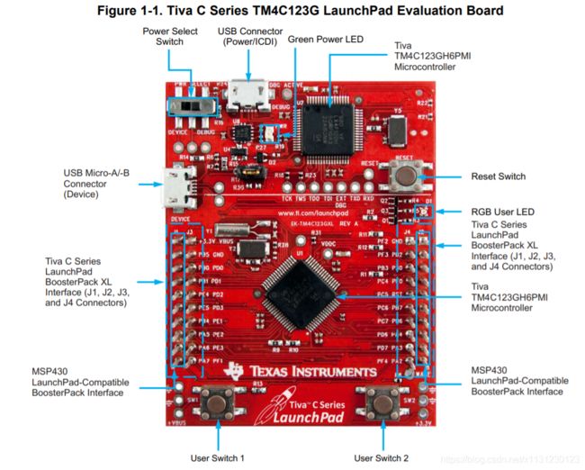
1 板子资源
板子用户手册
https://www.ti.com/lit/ug/spmu296/spmu296.pdf


2 开发环境
https://blog.csdn.net/x1131230123/article/details/103263355
3 例程
芯片手册
库函数包
3.1 PLL FPU 延时
外设编程教程
http://shukra.dese.iisc.ernet.in/edwiki/EmSys:Lab_Practicals_Using_TivaC_LaunchPad_Board
本节程序概览
#include 3.1.1 PLL
TM4C123GH6PM MCU具有四个不同的时钟源:
精密内部振荡器(PIOSC): 16 MHz。
主振荡器(MOSC):它可以使用外部时钟源或外部晶体。
低频内部振荡器(LFIOSC):片上内部30 kHz振荡器,用于深度睡眠节能模式。
休眠RTC振荡器(RTCOSC):可以配置为来自休眠(HIB)模块或HIB低频时钟源(HIB LFIOSC)的32.768 KHz外部振荡器源,旨在为系统提供实际的时钟源。

系统时钟由PLL产生,该PLL可以由5至25 MHz之间运行的任何晶体或振荡器驱动。PLL的输出频率始终为400 MHz,并且与输入时钟源无关。
两个时钟源,主OSC(MOSC)和精密内部osc(PIOSC)16 MHz,可以用作PLL的时钟源,并且可以通过MUX选择该时钟源。两个多路复用器(MUX)用于选择不同的时钟源,并且可以使用两种方法来创建要由CPU使用的系统时钟:
一种方法是使用锁相环(PLL)时钟发生器,该时钟发生器需要一个时钟源作为输入源来创建此系统时钟。
另一种方法是直接使用四个时钟源中的任何一个,并且可以通过MUX选择。一种简单的方法是使用精密内部OSC(16 MHz)除以4得到4 MHz的系统时钟。
库函数
#include "driverlib/sysctl.h"   /* 时钟 宏 */
SysCtlClockSet(SYSCTL_SYSDIV_5 | SYSCTL_USE_PLL | SYSCTL_OSC_MAIN | SYSCTL_XTAL_16MHZ);//设置为80MHZ工作频率
寄存器配置
#include "inc/tm4c123gh6pm.h"
#define SYSCTL_RIS_PLLLRIS      0x00000040  /* PLL Lock Raw Interrupt Status */
#define SYSCTL_RCC_XTAL_M       0x000007C0  /* Crystal Value */
#define SYSCTL_RCC_XTAL_6MHZ    0x000002C0  /* 6 MHz Crystal */
#define SYSCTL_RCC_XTAL_8MHZ    0x00000380  /* 8 MHz Crystal */
#define SYSCTL_RCC_XTAL_16MHZ   0x00000540  /* 16 MHz Crystal */
#define SYSCTL_RCC2_USERCC2     0x80000000  /* Use RCC2 */
#define SYSCTL_RCC2_DIV400      0x40000000  /* Divide PLL as 400 MHz vs. 200 MHz */
#define SYSCTL_RCC2_SYSDIV2_M   0x1F800000  /* System Clock Divisor 2 */
#define SYSCTL_RCC2_SYSDIV2LSB  0x00400000  /* Additional LSB for  SYSDIV2 */
#define SYSCTL_RCC2_PWRDN2      0x00002000  /* Power-Down PLL 2 */
#define SYSCTL_RCC2_BYPASS2     0x00000800  /* PLL Bypass 2 */
#define SYSCTL_RCC2_OSCSRC2_M   0x00000070  /* Oscillator Source 2 */
#define SYSCTL_RCC2_OSCSRC2_MO  0x00000000  /* MOSC */
#define Bus80MHz     4
void PLL_Init(void)
{
    /* 1) configure the system to use RCC2 for advanced features
     such as 400 MHz PLL and non-integer System Clock Divisor */
    SYSCTL_RCC2_R |= SYSCTL_RCC2_USERCC2;
    /* 2) bypass PLL while initializing */
    SYSCTL_RCC2_R |= SYSCTL_RCC2_BYPASS2;
    /* 3) select the crystal value and oscillator source */
    SYSCTL_RCC_R &= ~SYSCTL_RCC_XTAL_M; /* clear XTAL field */
    SYSCTL_RCC_R += SYSCTL_RCC_XTAL_16MHZ; /* configure for 16 MHz crystal */
    SYSCTL_RCC2_R &= ~SYSCTL_RCC2_OSCSRC2_M; /* clear oscillator source field */
    SYSCTL_RCC2_R += SYSCTL_RCC2_OSCSRC2_MO; /* configure for main oscillator source */
    /* 4) activate PLL by clearing PWRDN */
    SYSCTL_RCC2_R &= ~SYSCTL_RCC2_PWRDN2;
    /* 5) set the desired system divider and the system divider least significant bit */
    SYSCTL_RCC2_R |= SYSCTL_RCC2_DIV400; /* use 400 MHz PLL */
    SYSCTL_RCC2_R = (SYSCTL_RCC2_R & ~0x1FC00000) /* clear system clock divider field */
    + (Bus80MHz << 22); /* configure for 80 MHz clock */
    /* 6) wait for the PLL to lock by polling PLLLRIS */
    while ((SYSCTL_RIS_R & SYSCTL_RIS_PLLLRIS) == 0)
    {
        ;
    }
    /* 7) enable use of PLL by clearing BYPASS */
    SYSCTL_RCC2_R &= ~SYSCTL_RCC2_BYPASS2;
}
3.1.2 FPU
下面说一下开启FPU的方法:
首先,需要在编译器上开启FPU功能。CCS:默认为开启状态。可以在propertise——bulid——arm compiler——processor options 里的specify floating point support里配置,默认为FPv4SPD16 ,即开启状态。
其次,需要在代码里加上这两句 FPUEnable();FPULazyStackingEnable();(最好加在main函数入口处,具体原因我也不清楚。)
https://blog.csdn.net/chun_1959/article/details/50946392
http://home.eeworld.com.cn/my/space-uid-525682-blogid-242407.html
总而言之,单片机核心不是和运算符点运算,设计了FPU专门应用于浮点运算,这需要编译器的支持,编译器将程序中所有浮点运算都放置于FPU模块,这样可以减少CPU的负担,从而提升整体性能。
3.1.3 延时
#include "driverlib/sysctl.h"                                   /* 时钟 宏 */
void delay_ms( int ms )
{
    while ( ms-- )
        SysCtlDelay( SysCtlClockGet() / 3000 );         /* 延时1ms */
}
3.2 GPIO中,LED,KEY
#include 3.3 按键外部中断控制灯
#include 3.4 串口收发
#include 3.5 Flash写入与读取
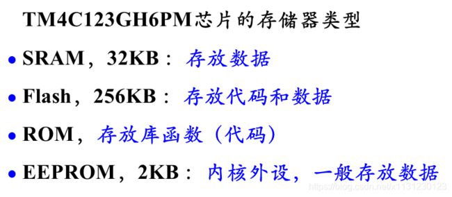
SRAM存临时数据,当CPU缓存。
EEPROM 一般操作这个存储系统数据,而不是操作Flash,操作Flash需要知道自己写的代码的大小占了多少,从而去写入没用到的Flash区域。
FLASH按块(BLOCK)操作,EEPROM按字节操作。FLASH成本低。
ROM 存储固化了的数据,比如一些固定指令和固定变量。
flash读写
#include 3.6 定时器 定时中断
#include 3.7 定时器 PWM输出
#include 3.8 定时器 计数捕获
#include 3.9 定时器 时间捕获
#include 3.10 读取模拟输入
3.11 两个按键+定时器 实验
//实验考试要求:定时0.8S,初始状态红灯闪烁,亮灭各0.8S; 按左键RGB轮流亮;按右键,三灯闪烁
#include