EA&UML日拱一卒-活动图::14.2 Behavior StateMachines (10)
英文原文来自UML2.5,作者提供中文翻译。
14.2.4 Notation(记法)
14.2.4.1 StateMachine Diagrams(状态机图)
StateMachine diagrams specify StateMachines. This Clause outlines the graphic elements that may be shown in StateMachine diagrams, and provides cross references where detailed information about the semantics and concrete notation for each element can be found. It also furnishes examples that illustrate how the graphic elements can be assembled into diagrams.
状态机图用于定义状态机。本节概括状态机图中可能出现的图形元素,并且提供相互对照,在这里可以找到关于每个元素语义和具体记法的信息。也会提供说明图形元素如何被组入状态机图中的例子。
A StateMachine diagram is a graph that represents a StateMachine. States and various other types of Vertices in the StateMachine graph are rendered by appropriate State and Pseudostate symbols, while Transitions are generally rendered by directed arcs that connect them, or by control symbols representing the actions of the Behavior on the Transition.
状态机图用来表现状态机。状态机图中的状态和各种类型的顶点通过适当的状态和伪状态记号来表示,而迁移通常表现为连接它们的有向弧线,还有通过控制记号表示迁移行为的动作。
14.2.4.2 StateMachine(状态机)
When depicting StateMachine redefinition in a class diagram, the default rectangle notation for Classifier can be used, with the keyword «statemachine» inside the name compartment above or before the name of the StateMachine.
如果在类图中表示状态机的重新定义,可以使用类目的默认矩形记号,但需要在名称区间中状态机名称的前面或上面加上关键词«statemachine»。
The association between a StateMachine and its context Classifier or BehavioralFeatures does not have a special graphical representation.
不存在特别的图形表达方式用于表现状态机和它的上下文类目或行为特征之间的关联。
14.2.4.3 Region(区域)
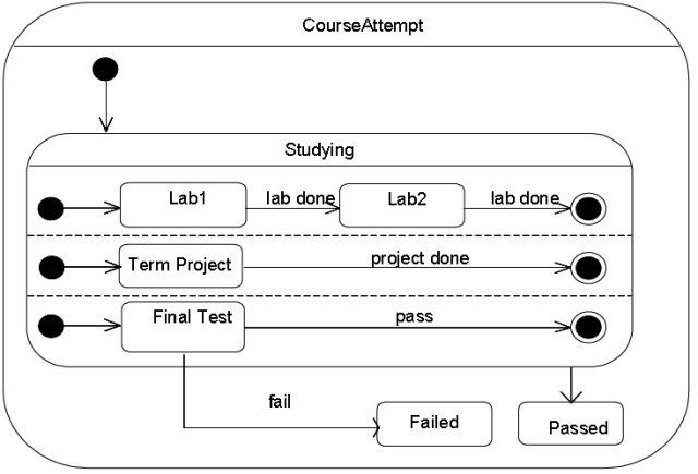
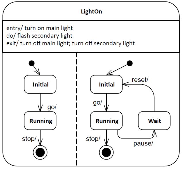
A composite State or StateMachine with Regions is shown by tiling the graph Region of the State/StateMachine using dashed lines to divide it into Regions (Figure 14.3). Each Region may have an optional name and contains the nested disjoint States and the Transitions between these. The text compartments of the entire State are separated from the orthogonal Regions by a solid line.
带有区域的组合状态或状态机的表示是通过将状态/状态机的图形区域平行排列来实现的,中间通过虚线分割(图14.3)。每个区域可以有可选的名称,嵌套的分离状态和状态之间的迁移。状态全体的文字分区通过实线和正交区域分离。
14.2.4.4 A composite State or StateMachine with just one Region is shown by showing a nested state diagram within the graph Region.
只有一个区域的组合状态或状态机表示为图形区域中的嵌套状态图。
Figure 14.3 Notation for a composite State with Regions
14.2.4.5 State(状态)
State is shown as a rectangle with rounded corners, with the State name shown within (Figure 14.4).
状态表示为圆角矩形,里面包含状态名。
Figure 14.4 State notation
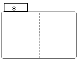
Optionally, it may have an attached name tab (Figure 14.5). The name tab is a rectangle, usually resting on the outside of the top side of a State and it contains the name of that State. It is normally used to keep the name of a composite State that has orthogonal Regions, but may be used in other cases as well.
作为可选项,状态可以有一个附属的名称标签(图14.5)。名称标签为长方形,通常停留在状态上边界的外侧,里面状态的名称。它通常用于保持包含正交区域的组合状态的名称,但也可以用于其他情况。
Figure 14.5 State with a name tab
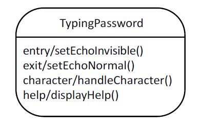
A State may be subdivided into multiple compartments separated from each other by a horizontal line (Figure 14.6).
Figure 14.6 State with compartments
The compartments of a State are:
状态的分区有:
• name compartment
名称分区
• internal Behaviors compartment
内部行为分区
• internal Transitions compartment.
内部迁移分区
A composite State also has a:
组合状态可以有:
• decomposition compartment.
分解分区。
Each of these compartments is described below.
各个分区的介绍如下:
• Name compartment(名称分区)
This compartment holds the (optional) name of the State, as a string. States without names are anonymous and are all distinct. It is undesirable to show the same named State twice in the same diagram, as confusion may ensue, unless control icons are used to show a Transition-oriented view of the StateMachine. Name compartments should not be used if a name tab is used and vice versa.
这个分区以文字列的形式保持(可选的)状态的名称。没有名称的状态是匿名和各不相同的。由于可能导致混淆,所以不希望在一个图中重复出现同样名称的状态。除非是通过控制图标来表示状态机的迁移发源视图。如果用了名称标签,就不应该使用名称分区,反之亦然。
In case of a submachine State, the name of the referenced StateMachine is shown as a string following ‘:’ after the name of the State.
子状态机状态的情况下,被引用状态机的名称作为文字列表示在状态名称和“:”之后。
• Internal activities Behaviors compartment(内部活动行为分区)
This compartment holds a list of internal Behaviors associated with a State. Each entry has the following format:
这个分区保持一个与状态关联的内部行为的列表。项目的格式下:
<行为类型标签> ['/' <行为表达式>]
The
<行为类型标签>用于识别通过<行为表达式>定义的行为的执行环境,可以使用下列中的一个:
o entry — This label identifies a Behavior, specified by the corresponding expression, which is performed upon entry to the State (entry Behavior).
进入-这个标签确定一个对应的表达式定义的行为,这个行为在进入一个状态时被执行(进入行为)。
o exit — This label identifies a Behavior, specified by the corresponding expression, that is performed upon exit from the State (exit Behavior).
退出-这个标签确定一个对应的表达式定义的行为,这个行为在退出一个状态时被执行(退出行为)。
o do — This label identifies an ongoing Behavior (doActivity Behavior) that is performed as long as the modeled element is in the State or until the computation specified by the expression is completed.
执行-这个标签确定一个持续执行的行为(doActivity行为),当建模的元素处于该状态,或者表达式定义的演算结束之前,这个行为都会被执行。
The optional
可选的<行为表达式>以文本形式语言表达,可以是供应商定义的,也可以是某些标准语言(参见16.1小节)
• Internal Transition compartment(内部迁移分区)
This compartment contains a list of internal Transitions, where each item has the following syntax:
这个分区包含内部迁移的列表,项目的语法如下:
{
{<触发条件>}* ['[' <监护条件>']'] [/<行为表达式>]
Where
<触发条件>是触发条件的记法(参见13.3.4小 节),<监护条件>是监护条件布尔型表达式,而可选的<行为表达式>定义了当符合内部迁移触发条件和监护条件的的事件发生时将会 被执行的效应行为。这个表达式以某种文本形式语言记述,可以是供应商定义的,也可以是某些标准语言(参见16.1小节)
Alternatively, in place of a textual behavior expression, the various Behaviors associated with a State or internal Transition can be expressed using the appropriate graphical representation in a separate diagram (e.g., an activity diagram).
也有可能,在记入文本形式行为表达式的位置,与状态或内部迁移关联的不同行为可以以适当的图形化方式表示为单独的图(比如活动图)。
14.2.4.5.1 Composite State(组合状态)
• decomposition compartment(分解分区)
This compartment shows its composition structure in terms of Regions, States, and Transition. In addition to the (optional) name and internal Transition compartments, the State may have an additional compartment that contains a nested diagram. For convenience and appearance, the text compartments may be shrunk horizontally within the graphic Region.
这个分区按照区域,状态,迁移来表示分解结构。除了(可选的)的名称和内部迁移分区,状态可以有追加的包含内嵌图的分区。为了保证便利和外观,该文本本区可以水平折叠到图形区域中。
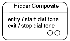
In some cases, it is convenient to hide the decomposition of a composite State. For example, there may be a large number of States nested inside a composite State and they may simply not fit in the graphical space available for the diagram. In that case, the composite State may be represented by a simple State graphic with a special “composite” icon, usually in the lower right-hand corner (see Figure 14.8). This icon, consisting of two horizontally placed and connected States, is an optional visual cue that the State has a decomposition that is not shown in this particular diagram. Instead, the contents of the composite State are shown in a separate diagram.
在某些情况下,隐藏组合状态的细节是便利的。例如组合状态 的内部可能嵌入了大量的状态,而且不能简单地使用图形内部的可用空间。这时,组合状态可以被表示为带有特殊的“组合”图标的简单状态,位置通常是在右下角 (参见图14.8).这个图标由两个水平放置,连接在一起的状态组成。是一种可选的可视化方式,暗示该状态有更多细节没有在该图中表示。相反,组合状态的 内容被表示在另外一个图中。
NOTE. The “hiding” here is purely a matter of graphical convenience and has no semantic significance in terms of access restrictions.
注意:这里的隐藏存粹是为了图形上的便利,它在访问限制方面不具有任何的语义。
A composite State may have one or more entry and exit points on its outside border or in close proximity of that border (inside or outside).
组合状态可以在它的外边界上或者是非常接近外边界(里面或外面)的位置有一个或多个进入和退出点。
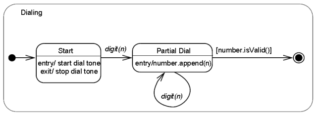
Figure 14.7 Composite State with two States
Figure 14.8 Composite State with a hidden decomposition indicator icon
Figure 14.9 Composite State with Regions
Figure 14.10 Composite State with two Regions and entry, exit, and do Behaviors
14.2.4.5.2 Submachine State(子状态机状态)
The submachine State is depicted as a normal State where the string in the name compartment has the following syntax:
子状态机状态像普通状态一样表示,只是名称分区遵从下面的语法。
<状态名> ‘:’ <引用的状态机名称>
The submachine State symbol may contain the references to one or more entry points and to one or more exit points. The notation for these connection point references comprises entry/exit Pseudostates on the border of the submachine State.The names are the names of the corresponding entry/exit points defined within the referenced StateMachine (see ConnectionPointReference).
子状态机状态记法包含指向一个或多个进入点和一个或多个退出点的引用。这些连接点引用的符号在状态机边界上构成进入/退出伪状态。它们的名称是与之对应的定义在被引用的状态机内部的进入/退出点的名称(参见连接点引用)。
If the submachine StateMachine is entered through its default initial Pseudostate or if it is exited as a result of the completion of the submachine, it is not necessary to use the entry/exit point notation. Similarly, an exit point is not
required if the exit occurs through an explicit group Transition that originates from the boundary of the submachine State (implying that it applies to all the substates of the submachine).
如果子状态机通过默认的初始伪状态进入或者因为动作完成而退出,没有必要使用进入/退出点符号。类似地,当由一组明确的来自子状态机状态边界的迁移所引起的退出发生时也不需要退出点。
Submachine States invoking the same submachine may occur multiple times in the same state diagram with the entry and exit points being part of different Transitions.
入口点和退出点是不同迁移的一部分,子状态机状态对同一个状态机的调用可以在一个状态图中多次发生。
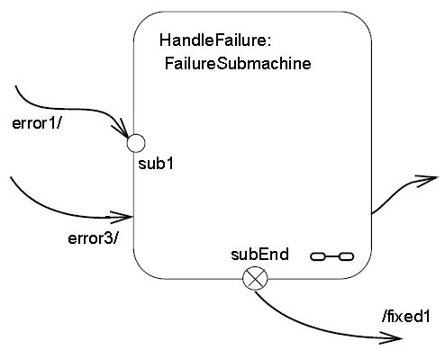
The diagram in Figure 14.11 shows a fragment from a StateMachine diagram in which a submachine State (the FailureSubmachine) is referenced. The actual submachine StateMachine is defined in some enclosing or imported
namespace.
Figure 14.11 Submachine State example
In the above example, the Transition triggered by Event “error1” will terminate on entry point “sub1” of the FailureSubmachine StateMachine. The “error3” Transition implies taking the default Transition of the FailureSubmachine.
The Transition originating from the “subEnd” exit point of the submachine will execute the “fixed1” Behavior in addition to what is executed within the HandleFailure StateMachine. This Transition must have been triggered within the HandleFailure StateMachine. Finally, the Transition originating from the edge of the submachine State is taken as a result of the completion event generated when the FailureSubmachine reaches its FinalState.
在上面的例子中,被事 件"error1"触发的迁移终止于FailureSubmachine状态机的入口点"sub1"。"error3"迁移暗示的是 FailureSubmachine的默认迁移。除了在HandleFailure状态机内部的执行以外,源自"subEnd"退出点的迁移将会执 行"fixed1"行为。这个迁移肯定是在HandleFailure状态机内部被触发的。最后,当FailureSubmachine到达完了状态时, 会发生源自子状态机边界的迁移。
NOTE. The same notation would apply to composite States with the exception that there would be no reference to a StateMachine in the State name.
注意:同样的符号也可以应用到包含异常的状态,这时状态名称中不会包含状态机的引用。
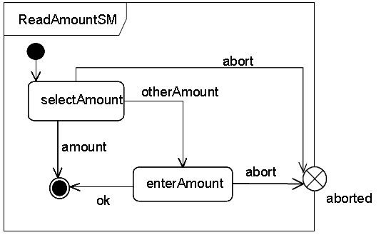
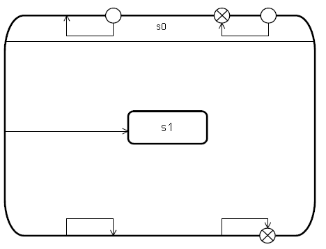
Figure 14.12 is an example of a StateMachine defined with two exit points. Entry and exit points may be shown on the frame or within the state graph. Figure 14.12 is an example of a StateMachine defined with an exit point shown within the state graph. Figure 14.13 shows the same StateMachine using a notation shown on the frame of the StateMachine.
图14.12是一个定义了两个退出点的状态机的例子。进入和退出点可以显示在边框上或者是状态图形的内部。图14.12是一个状态机的退出点显示在状态图形内部的例子。图14.13表示的是同一个状态机,但是使用的符号表示在状态机的边框上。
Figure 14.12 StateMachine with an exit point as part of the StateMachine graph
Figure 14.13 StateMachine with an exit point on the border
In Figure 14.14 the StateMachine shown in Figure 14.13 is referenced in a submachine State, and the presentation option with the exit points on the State symbol is shown.
在图14.14中,图14.13中的状态机在一个子状态机状态中被引用,表示选项为在状态符号中显示退出点。
Figure 14.14 Submachine Sate that uses an exit point
An example of the notation for entry and exit points for composite States is shown in Figure 14.23.
组合状态中的进入和退出点记法的例子是图14.23.
14.2.4.5.3 State list notation(状态列表记法)
State lists provide a graphical shortcut for certain situations that sometimes occur in practice.
状态列表为实际发生的特定情况提供了一种图形化的快捷方式。
NOTE. These are purely notational forms with no corresponding abstract syntax representation. They are interchanged with UML DI, see Annex B.4.4.
注意:这是纯粹的符号形式,不存在与之对应的抽象语法表现。它们通过UML ID实现互换,参见附录B.4.4。
Multiple effect-free Transitions with the same Trigger values originating on different States but all either (a) targeting a common junction Vertex with a single outgoing Transition or (b) terminating on the same target State, may be represented by a Single Transition-like arc originating from a State-like graphic element, labeled with a list of the names of the originating States. This arc terminates on the joint target State. Figure 14.15 shows both possibilities and Figure 14.16 shows the equivalent diagram without using statelists.
多个具有相同监护条件的不包含效应行为的迁移 来自不同的状态,都同样通过一个离开迁移指向共同的汇合顶点,或者终止与同一个状态,可以表现为一个起源于类状态图形元素的类迁移弧线,弧线以源状态名称 的列表标记。图14.15表示了两种可能的情况,而14.16表示了没有使用状态列表时的等价图。
Figure 14.16 Diagram equivalent to Figure 14.15 without using statelists
14.2.4.6 FinalState(完了状态)
A FinalState is shown as a circle surrounding a small solid filled circle (see Figure 14.17). The corresponding completion Transition on the enclosing State has as notation an unlabeled Transition.
完了状态表示为一个被圆形包围一个小的实心填充圆形(参见图14.17).对应的外围状态的完成迁移通过无标记迁移来表示。
Figure 14.17 FinalState notation
Figure 14.7 has an example of a FinalState (the right-most of the States within the composite State).
图14.7中有一个完了状态的例子(组合状态中最右边的状态)。
14.2.4.7 Pseudostate(伪状态)
An initial Pseudostate is shown as a small solid filled circle (see Figure 14.18). In a Region of a ClassifierBehavior StateMachine, the Transition from an initial Pseudostate may be labeled with the Event type of the occurrence that creates the object; otherwise, it must be unlabeled. If it is unlabeled, it represents any Transition from the enclosing State.
初始伪状态表示为一个小的实心圆形(图14.18)。在类目行为状态机的区域中,源于初始伪状态的迁移可以被标记为创建对象的事件发生类型。否则,一定是无标记的。如果是无标记的,那么它表现就是源自外围状态的所有迁移。
Figure 14.18 initial Pseudostate
A shallowHistory Pseudostate is indicated by a small circle containing an ‘H’ (see Figure 14.19). It applies to the State Region that directly encloses it.
浅历史伪状态显示为包含‘H’的小圆形(参见图14.19)。它应用于直接包含它的状态区域。
Figure 14.19 shallowHistory Pseudostate
A deepHistory Pseudostate is indicated by a small circle containing an ‘H*’ (see Figure 14.20). It applies to the State Region that directly encloses it.
深历史伪状态显示为包含‘H*’的小圆形(参见图14.20)。它应用于直接包含它的状态区域。
Figure 14.20 deepHistory Pseudostate
An entry point is shown as a small circle on the border of the StateMachine diagram or composite State, with the name associated with it (see Figure 14.21).
进入点表示为在状态机图或组合状态边界上的一个小圆,带有与之关联的名称(参见图14.21)。
Figure 14.21 entryPoint Pseudostate
Optionally it may be placed both within the StateMachine diagram and outside the border of the StateMachine diagram or composite State.
它既可以放到状态机图的内部,也可以放到状态机图或组合状态的边界上。
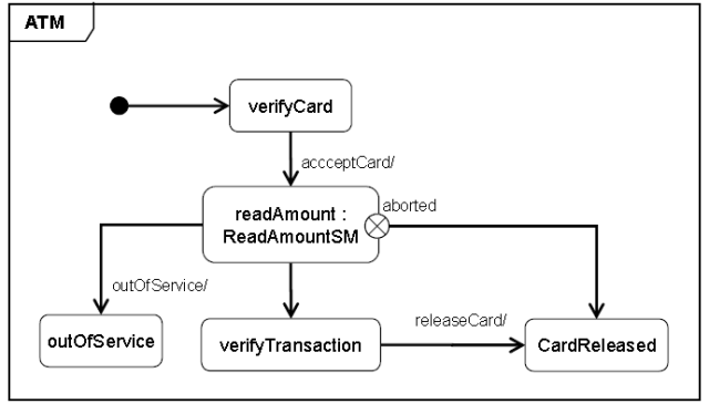
An exit point is shown as a small circle with a cross on the border of the StateMachine diagram or composite State, with the name associated with it (see Figure 14.22).
退出点表示为位于状态机图或组合状态边界上的内部有×的小圆,具有与之相关联的名称(参见图14.22)。
Figure 14.22 exitPoint Pseudostate
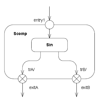
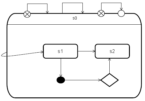
Optionally, an exit point symbol may be placed both within the StateMachine diagram or composite State and outside the border of the StateMachine diagram or composite State. Figure 14.23 illustrates the notation for depicting entry and exit points of composite States.
Figure 14.23 entryPoint and exitPoints on a composite State
Alternatively, the “bracket” notation shown in Figure 14.30 and Figure 14.31 can also be used for the transition-oriented notation.
或者,图14.30,图14.31中的中括号也可以用于面向迁移的记法。
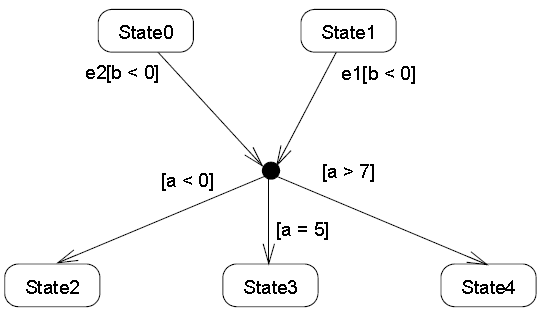
A junction is represented by a small filled circle (see Figure 14.24).
连接点通过一个小的填充圆形来表现(参见图14.24)。
Figure 14.24 junction Pseudostate with incoming and outgoing Transitions
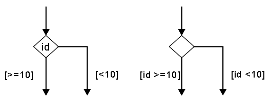
A choice Pseudostate is shown as a diamond-shaped symbol as exemplified shown by the left-hand diagram in Figure 14.25.
如图14.25中左侧图形中举例说明的那样,选择伪状态表示为菱形符号。
Figure 14.25 choice Pseudostates
NOTE. In cases when all guards associated with triggers of Transitions leaving a choice Pseudostate are binary expressions that share a common left operand, then the notation for choice Pseudostate may be simplified. The left operand may be placed inside the diamond-shaped symbol and the rest of the Guard expressions placed on the outgoing Transitions. This is illustrated by the right-hand diagram in Figure 14.25.
注意:如果离开选择伪状态的迁移条件的监护条件都是二元表达式,且拥有共同的左侧操作数,那么选择伪状态的记法可以简化。左侧操作数可以放到菱形符号内部,监控条件的其他操作数可以放到离开迁移上。这种情况表示在图15.25的右侧。
A terminate Pseudostate is shown as a cross, see Figure 14.26.
中止伪状态表示为一个×,参见图14.26。
Figure 14.26 terminate Pseudostate
The notation for a fork and join is a short heavy bar (Figure 14.27). The bar may have one or more arrows from source States to the bar (when representing a join). The bar may have one or more arrows from the bar to States (when representing a fork). A Transition string may be shown near the bar.
分叉和汇合的记法是短粗线条(图14.27)。线条可以有一个或多个来自源状态的箭头(当表示汇合时)。也可以有一个或多个从线条到状态的箭头(当表现分叉时)。在线条附近可以表示迁移文字列。
Figure 14.27 fork and join Pseudostates
14.2.4.8 ConnectionPointReference(连接点引用)
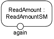
A connection point reference to an entry point has the same notation as an entry Pseudostate. The circle is placed on the border of the State symbol of a submachine State.
指向进入点的连接点引用的记法和进入伪状态相同。圆形符号放置在状态机状态的状态符号的边界上。
Figure 14.28 Entry point ConnectionPointReference notation
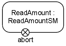
A connection point reference to an exit point has the same notation as an exit Pseudostate. The encircled cross is placed on the border of the State symbol of a submachine State.
指向退出点的连接点引用的记法和退出点伪状态相同。被圆形围绕的X被放置到状态机状态的状态符号的边界上。
Figure 14.29 Exit point ConnectionPointReference notation
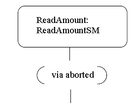
Alternatively, a connection point reference to an entry point can also be visualized using a “bracketed space” symbol as shown in Figure 14.30. The text inside the symbol shall contain ‘via’ followed by the name of the connection point. This notation may only be used if the Transition ending with the connection point is defined using the graphical Transition notation, such as the one shown in Figure 14.32.
Figure 14.30 Alternative entry point ConnectionPointReference notation
A connection point reference to an exit point can also be visualized using a “bracketed space” symbol as shown in Figure 14.31. The text inside the symbol shall contain ‘via’ followed by the name of the connection point. This notation may only be used if the Transition associated with the connection point is defined using the graphical Transition notation such as the one shown in Figure 14.32.
指向退出点的连接点引用也可以表示成一个如图14.31所示的“括号空间”符号。符号内的文字应该包含'var',其后跟着连接点的名称。这种记法应该只有当与连接点关联的迁移是通过像图14.32中那样的图形化迁移记法定义时使用。
Figure 14.31 Alternative exit point ConnectionPointReference notation
14.2.4.9 Transition(迁移)
The default textual notation for a Transition is defined by the following BNF expression:
迁移的默认记法通过下面BNF表达式定义:
[
[<触发条件> [‘,’ <触发条件>]* [‘[‘ <监护条件>’]’] [‘/’ <行为表达式>]]
Where
这里<触发条件>适用触发条件的标准记法(参见13.3.4小 节),
As an alternative, in cases where the effect Behavior can be described as a control-flow based sequence of Actions, there is a graphical representation for Transitions and compound transitions which is similar to the notation used for
Activities.
或者,当效应行为可以被描述成控制流形式的动作序列时,可以用与活动图中用到的记法相似的图形化方式来表达迁移或复合迁移。
NOTE. Although this alternative notation contains graphical elements reminiscent of the notation used for Activities, it is a distinct form applicable only to StateMachines, and its elements map to appropriate StateMachine concepts.
注意:尽管这种变化的记法中包含的元素使人联想到活动中使用的记法,但它是不同的形式,只能在状态机中使用。而且它的元素映射的是状态机中的概念。
This notation is in the form of a directed graph, which consists of one or more graphical symbols interconnected by directed arcs that represent control flow (see Figure 14.32). In all cases except for the Transition originating from the
initial Pseudostate, the starting symbol, which has the form of the standard simple State notation, represents the source State of the Transition. If this Transition has a Signal-based Trigger, then the source state symbol is connected by an arc pointing to a special Signal receipt symbol described below. If there are multiple Triggers for the Transition, they are all listed in the same symbol as explained below.
这是直接表示为图形形式的记法,包含一个或多个由表现控制流的有向弧线连接的图形符号(参见图 14.32)。对于除了源自初始伪状态的迁移以外的所有情况,标准的简单状态的开始符号表现的是迁移的源状态。如果迁移具有信号类的触发条件,那么源状态 符号被一个下面定义的,指向特殊信号接受符号连接。如果迁移有多个触发条件,它们在下面说明的同一个符号中一起列出。
If the Transition originates from the initial Pseudostate, the starting symbol is the initial symbol, which is the same as used for the initial Pseudostate: a filled black circle. In that case, there is no Signal receipt symbol immediately
following the starting symbol.
如果迁移源自初始伪状态,开始符号是初始符号,是和初始伪状态一样的实心圆形。这种情况下,开始符号的后面不会立即跟着一个信号接收符号。
Except for end symbols that terminate the paths, any of the following symbols can appear in the chain as appropriate:
除了结束路径的符号,下面任何的符号都可以出现在符号链中。
· an action symbol(动作符号)
· a choice point symbol(选择点符号)
· a Signal send symbol(信号发送符号)
· a merge symbol(合并符号)
The terminating symbol in these directed graphs is always either a State-like symbol representing the target State of the transition or a final state symbol (which is the same as the symbol for a FinalState).
在这个有向图形中,结束符号要么是表示迁移目标状态的类状态符号,要么是一个完了状态符号(它和完了状态的符号相同)
14.2.4.9.1 Action symbols(动作符号)
Each action symbol is represented by a rectangle with an optional textual specification of the action. It maps either to an OpaqueAction or to a SequenceNode containing one or more Actions executed in sequence (see sub clause 16.11.3) and which are part of the Activity specifying the effect Behavior of the appropriate Transition in the compound transition.
动作符号表示为矩形,该矩形带可选的定义动作内容的文本。动作可以映射到一个OpaqueAction或包含一个或多个按照次序执行的动作的SequenceNode(参见16.11.3),它是定义复合迁移中关联迁移的效应行为的活动的一部分。
14.2.4.9.2 Signal receipt symbol(信号接受符号)
The Signal receipt symbol is shown as a five-pointed polygon that looks like a rectangle with a triangular notch in one of its sides (either one). It maps to the trigger of the Transition and does not map to an Action of the Activity that
specifies the effect Behavior. The names of the Signals of the Trigger as well as any guard are contained within the symbol as follows:
信号接受符号表示为五点多边形,看起来像一个某一边带有三角形切口的矩形。它与迁移的触发条件对应,但不会对应定义了效应行为中的动作。被包含的触发条件和监护条件的信号名称遵从下面的形式:
<触发条件> [‘,’ <触发条件>]* [‘[‘ <监护条件> ‘]’]
Where
像13.3.4小节中描述的那样,<触发条件>的类型只允许信号和变化事件。触发条件符号总是位于符号路径的开头并且复合迁移中最多只允许有一个这样的符号。
14.2.4.9.3 Signal send symbol(信号发送符号)
This represents the special action of sending a signal and maps directly to a SendSignalAction that is part of the Activity that describes the effect Behavior of the corresponding Transition. The notation corresponds to the notation for the SendSignalAction (see sub clause 16.3.4).
这个符号表现发送信号的动作,它直接对应SendSignalAction动作。这个动作是描述对应迁移的效应行为的活动的一部分。它的记法对应与SendSignalAction动作的记法(参见16.3.4小节)。
14.2.4.9.4 Choice point symbol(选择符号)
This symbol maps directly to a choice Pseudostate and uses the same notation.
这个符号直接对应选择伪状态而且使用同样的记法。
NOTE. It is not part of any Activity.
注意:它不是活动的一部分。
14.2.4.9.5 Merge symbol(合并符号)
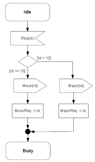
A merge symbol is used to join multiple control-flow arcs and maps directly to a junction Pseudostate and uses the same notation. It is not part of any Activity. Figure 14.32 shows a compound transition consisting of four connected Transitions: one from the Idle State to the choice symbol, one for each of the branches of the choice through the junction symbol, and one from the junction
Pseudostate to the Busy State.
合并符号用于将多个控制流弧线连接在一起,直接对应连接点伪状态并使用相同的记法。它不属于任何活动。图14.32表示了包含4个相连迁移的复合迁移:一个从Idel状态到选择符号,两个通过连接点符号的选择分支,一个从连接点伪状态到Busy状态。
Figure 14.32 Symbols for Signal reception, Sending, and Actions on a Transition
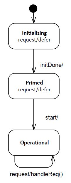
14.2.4.9.6 Deferred triggers(延缓触发条件)
A deferrable trigger is shown by listing it within the State followed by a slash and the label “defer”. An example of this notation is shown in Figure 14.33. In this example, handling of the “request” event occurrence is deferred in States
“Initializing” and “Primed”. However, it will be handled once the “Operational” State is reached.
Figure 14.33 Deferred Trigger notation
14.2.4.10 TransitionKind(迁移种类)
• Transitions of the kind internal are not shown explicitly in diagrams.
图中不会明确地表示内部迁移。
• Transitions of the kind local can originate from the border of the containing composite State, or one of its entry points, or from a Vertex within the composite State. (Alternatively, a Transition of kind local can be shown as a Transition leaving a State symbol containing the text “*.” The Transition is then considered to belong to the enclosing composite State.) Transitions of this kind can only terminate on the border of the composite State, or one of its exit points, or on a Vertex within the composite State. All of the Transitions in Figure 14.34 are local.
局部迁移可以源自包含它的组合状态的边界或某个进入点,或者组合状态内部的顶点。(或者,局部迁移可以表示为包含文字“*”的 离开状态的迁移。该迁移可以看作是属于外围组合状态的。)这种类型的迁移可以终止于组合状态的边界,或某个退出点,或组合状态内的某个顶点。图14.34 中的所有迁移都是局部迁移。
• Transitions of kind external can target any Vertex contained within or external to the source Vertex. The part of the external Transition closest to the source must be drawn outside of the source Vertex border. In the case of an external self Transition where the source is a State or exit point on the State, it may target the State itself or an entry point on the State and it will be drawn completely outside of the State border. All of the Transitions in Figure 14.35 are external.
外部迁移的目标顶点可以是任何源顶点内部或外部的顶点。靠近迁移源的外部迁移必须画在源顶点边界 的外面。在外部自迁移的情况下,如果迁移源是状态或者状态的退出点,迁移目标可以是那个状态本身或者该状态的进入点,而且迁移应该被完全地描画在状态边界 的外边。图14.35中所有的迁移都是外部的。
Figure 14.34 Local Transitions
Figure 14.35 External Transitions
参考资料:
《OMG Unified Modeling Language TM (OMG UML) Version 2.5》
