脉动进位计数器
1,今天学习的是采用数据流建模的方式编程
(数据流建模,采用连续赋值语句的方式,根据数据流在寄存器之间的流动及处理过程对电路进行描述。其中,连续赋值语句有些类似于门级建模)
(1)采用数据流一个带复位端的下降沿D触发器的设计:
module edge_off(q,qbar,d,clk,clear);
input d,clk,clear;
output q,qbar;
wire s,sbar,r,rbar,cbar;
//(连续赋值语句,有点类似于门结构)
assign cbar=~clear;
// and (nsbar,rbar,s); not (sbar,nsbar);
//上面这两个门器件语句 等同于下面这个连续赋值语句; 由此可以类推将数据流建模转换成门级建模
assign sbar=~(rbar&s);
assign s=~(sbar&cbar&~clk);
assign r=~(rbar&s&~clk);
assign rbar=~(r&cbar&d);
assign q=~(s&qbar);
assign qbar=~(cbar&q&r);
endmodule
(2)T触发器的Verilog描述
`include "edge_off.v"
module T_ff(q,clk,clear);
output q;
inout clk,clear;
edge_off off(q,,~q,clk,clear);
endmodule
(3)带异步复位的下降沿脉动计数器:
`include "T_ff.v"
module counter(q,clock,clear);
input clock,clear;
output [3:0]q;
T_ff t1(q[0],clock,clear);
T_ff t2(q[1],q[0],clear);
T_ff t3(q[2],q[1],clear);
T_ff t4(q[3],q[2],clear);
endmodule
(4)testbench模块:
//关键的还是(1)声明输入输出变量;(2)模块实例化,调用模块;(3)变量初始化,并赋值;
`include "counter.v"
module stimulus;
//输入定义为reg类型,输出定义为wire类型
reg CLOCK,CLEAR;
wire [3:0]Q;
//监视输出语句
initial
$monitor($time,"counter Q=%b Clear=%b",Q[3:0],CLEAR);
//模块实例化,调用模块,我总是忘了定义对象名称c
counter c(Q,CLOCK,CLEAR);
//给输入变量初始化赋值
initial
begin
CLEAR=1'b1;
#34 CLEAR=1'b0;
#50 CLEAR=1'b0;
#200 CLEAR=1'b1;
#400 CLEAR=1'b0;
end
initial
begin
CLOCK=1'b0;
forever #10 CLOCK=~CLOCK;
end
/*initial
begin
#400 $finish;
end*/
endmodule
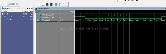
(5)仿真图形:
2,采用行为建模方式,描述电路
//只关注电路要实现一个怎样的功能,而不考虑具体的电路结构以及数据流的流动情况
(1)D触发器的设计
module D_FF(d,q,clk,reset);
inout d,clk,reset;
output q;
reg q;
//行为建模,只关注要实现的功能,程序相对于第一种要简洁的多。
always @(posedge reset or negedge clk)
begin
if(reset)
q=1'b0;
else
q<=d;
end
endmodule
(2)其他模块与方法1中的是类似的。
3,采用UDP编写普通电平敏感的D触发器:
primitive udp_latch(q,d,clock,reset);
output q;
input d,clock,reset;
reg q;
initial
q=0;
table
? ? 1 : ? : 0;
0 1 0 : ? : 0;
1 1 0 : ? : 1;
? 0 0 : ? : -;
endtable
endprimitive
4,采用UDP编写边沿敏感的D触发器:
primitive edge_off(q,d,clock,reset);
output q;
input d,clock,reset;
reg q;
initial
q=0;
table
? ? 1 : ? : 0;
? ? (10) : ? : -;
0 (10) 0 : ? : 0;
1 (10) 0 : ? : 1;
? (1x) 0 : ? : -;
? (0x) 0 : ? : -;
? (x1) 0 : ? : -;
(??) ? 0 : ? : -;
endtable
endprimitive
5、若采用UDP编写脉动计数器,则不需要编写D触发器模块,只需要编写T触发器模块,再调用即可,如下:
(1)、T触发器模块:
primitive T_FF(output reg q,input clk,clear);
table
? 1 : ? :0;
? (10) : ? : -;
(10) 0 : 1 : 0;
(10) 0 : 0 : 1;
(0?) 0 : ? : -;
endtable
endprimitive
(2)、四位脉动计数器模块:
`include "T_FF.v"
module counter(Q,CLOCK,Reset);
output [3:0]Q;
input CLOCK,Reset;
T_FF tff0(Q[0],CLOCK,Reset);
T_FF tff1(Q[1],Q[0],Reset);
T_FF tff2(Q[2],Q[1],Reset);
T_FF tff3(Q[3],Q[2],Reset);
endmodule
(3)仿真图形: