数字电路实现简单CPU
数字电路实现简单CPU
一、设计目的
贯彻以CPU设计为核心,以层次化、模块化设计方法为抓手的组织思路,培养学生设计与实现数字系统的能力。本设计要求在进行了多个单元实验后,综合利用所学的理论知识,并结合在单元实验中所积累的成果(包括已经设计好的功能部件和调试方法),设计出一个简易计算机系统。
二、设计内容
按给定的数据格式和指令系统,使用EDA工具设计一台用硬连线逻辑控制的简易计算机系统;要求灵活运用各方面知识,使得所设计的计算机系统具有较佳的性能;对所做设计的性能指标进行分析,整理出设计报告。
1、数据格式
数据字采用8位二进制定点补码表示,其中最高位(第7位)为符号位,小数点可视为最左或最右,其数值表示范围分别为:-1≤X<1或-128≤X<127。
2、寻址方式
指令的高4位为操作码,低4 位分别用2位表示目的寄存器和源寄存器的编号,或表示寻址方式。本机有2种寻址方式。
(1) 寄存器直接寻址
当R1和R2均不是“11”时,R1和R2分别表示两个操作数所在的寄存器地址,R1为目标寄存器地址,R2为源寄存器。
| 地址R1或R2的值 | 指定的寄存器 |
|---|---|
| 00 | A寄存器 |
| 01 | B寄存器 |
| 10 | C寄存器 |
(2) 寄存器间接寻址
当R1或R2中有一个为“11”时,表示相应操作数的地址在C寄存器中,操作数在RAM
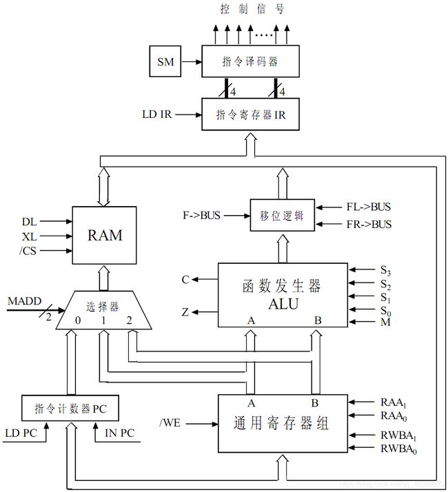
3.数据通路

4.指令系统

三、 详细设计
3.1设计的整体架构
3.2各模块的具体实现
1.8位PC计数器
library ieee;
use ieee.std_logic_1164.all;
use ieee.std_logic_unsigned.all;
entity PC_8 is
 port(CLK:in std_logic;
   IN_PC:in std_logic;
   LD_PC:in std_logic;
   PC_DATA:in std_logic_vector(7 downto 0);
   OUT_PC:out std_logic_vector(7 downto 0));
end PC_8;
architecture test of PC_8 is
signal temp:std_logic_vector(7 downto 0);
begin
 process(PC_DATA,CLK,IN_PC,LD_PC)
 begin
  if((CLK'event and CLK='1')and(IN_PC='1')and(LD_PC='0')) then
   temp<=temp+"00000001";
  elsif((CLK'event and CLK='1')and(IN_PC='0')and(LD_PC='1')) then
   temp<=PC_DATA;
  end if;
 end process;
 OUT_PC<=temp;
end test;
本模块用于对指令进行计数,并用于自增递进与赋地址给RAM。PC_DATA用于接受外部输入地址,IN_PC用于自增,LD_PC表接受外部输入,在上升沿进行操作

2.srg_3_8寄存器组
library ieee;
use ieee.std_logic_1164.all;
use ieee.std_logic_unsigned.all;
entity srg_3_8 is
port(CLK,WE:in std_logic;
  RAA1,RAA2,RWBA1,RWBA2:in std_logic;
  I:in std_logic_vector(7 downto 0);
  AO,BO:out std_logic_vector(7 downto 0));
end srg_3_8;
architecture test of srg_3_8 is
signal A:std_logic_vector(7 downto 0):="00000001";
signal B:std_logic_vector(7 downto 0):="00000010";
signal C:std_logic_vector(7 downto 0):="00000100";
begin
 process(A,B,C,RAA1,RAA2,RWBA1,RWBA2)
 begin
  if(WE='1') then
   if(RAA1='0' and RAA2='0') then
    AO<=A;
   elsif(RAA1='0' and RAA2='1') then
    AO<=B;
   elsif(RAA1='1' and RAA2='0') then
    AO<=C;
   end if;
   if(RWBA1='0' and RWBA2='0') then
    BO<=A;
   elsif(RWBA1='0' and RWBA2='1') then
    BO<=B;
   elsif(RWBA1='1') then--if rwba=0,ALU,else MOVc
    BO<=C;
   end if;
  elsif(WE='0' and (CLK'event and CLK='0')) then
   if(RWBA1='0' and RWBA2='0') then
    A<=I;
   elsif(RWBA1='0' and RWBA2='1') then
    B<=I;
   elsif(RWBA1='1') then--if rwba2=0,ALU,else MOVb
    C<=I;
   end if;
  end if;
 end process;
end test;
通过调节RAA与RWBA的值,来进行寄存器组内值的互相调换与外界的赋值存储

3.三选一多路复用器
library ieee;
use ieee.std_logic_1164.all;
use ieee.std_logic_unsigned.all;
entity three_one is
port(MADD:in std_logic_vector(1 downto 0);
     in_pc,in_a,in_b:in std_logic_vector(7 downto 0);
     out_choice:out std_logic_vector(7 downto 0));
end three_one;
architecture test of three_one is
signal temp:std_logic_vector(7 downto 0);
begin
 process(MADD,in_pc,in_a,in_b)
 begin
 if(MADD = "00") then
 temp<=in_pc;
 elsif(MADD = "01") then
 temp<=in_a;
 elsif(MADD = "10") then
 temp<=in_b;
 end if;
 end process;
 out_choice<= temp;
end test;
用于选择输入端

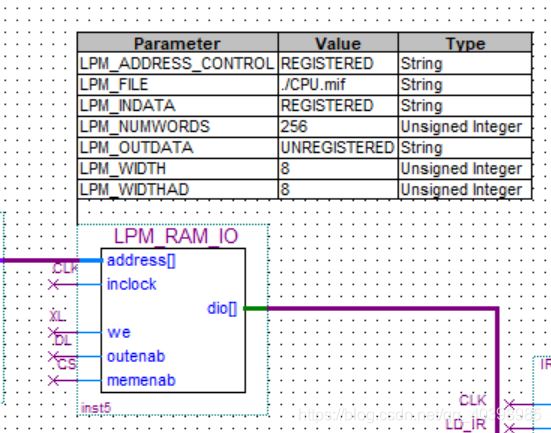
4.RAM

使用库自带RAM,并根据具体功能选择端口,存储并输出各指令码
5.ALU
library ieee;
use ieee.std_logic_1164.all;
use ieee.std_logic_unsigned.all;
entity ALU is
port (IN_A,IN_B:in std_logic_vector(7 downto 0);
      S:in std_logic_vector(3 downto 0);
      M:in std_logic;
      C,Z:out std_logic;
      OUT_ALU:out std_logic_vector(7 downto 0));
end ALU;
architecture test of ALU is
signal temp:std_logic_vector(8 downto 0);
signal final:std_logic_vector(7 downto 0);
signal r1,r2:std_logic_vector(1 downto 0);
begin
 process(IN_A,IN_B,S,M)
 begin
 C<='0';
 Z<='0';
 if(M='1') then
  if(S="1001")then
   temp<=('0'&IN_A)+('0'&IN_B);
   C<=temp(8);
   final<=temp(7 downto 0);
  elsif(S="0110")then
   final<=IN_A-IN_B;
  elsif(S="1011")then
   final<=IN_A or IN_B;
  elsif(S="0101")then
   final<= not IN_A;
  end if;
 elsif(M='0') then
  final<=IN_A;
 end if;
 if(final="00000000") then
  Z<='1';
 end if;
 end process;
 OUT_ALU<=final;
end test;
在ALU中进行加,减,与,否四种运算,并且输出进位与判断是否全0,用于跳转指令。

6. 逻辑移位
library ieee;
use ieee.std_logic_1164.all;
use ieee.std_logic_unsigned.all;
entity logic_move is
port(FL_BUS,FR_BUS,F_BUS:in std_logic;
  IN_ALU:in std_logic_vector(7 downto 0);
  Cf:out std_logic;
  OUT_MOVE:out std_logic_vector(7 downto 0));
end logic_move;
architecture test of logic_move is
begin
 process(IN_ALU,FL_BUS,FR_BUS,F_BUS)
 begin
 OUT_MOVE<="ZZZZZZZZ";
 Cf<='Z';
 if(IN_ALU="ZZZZZZZZ")then
  OUT_MOVE<="ZZZZZZZZ";
 else
  if(FR_BUS='0' and FL_BUS='0' and F_BUS='1') then
   OUT_MOVE<=IN_ALU;
  elsif(FR_BUS='1' and FL_BUS='0' and F_BUS='0') then
   OUT_MOVE<=IN_ALU(0) & IN_ALU(7 downto 1);
   Cf<=IN_ALU(0);
  elsif(FR_BUS='0' and FL_BUS='1' and F_BUS='0')then
   OUT_MOVE<=IN_ALU(6 downto 0) & IN_ALU(7);
   Cf<=IN_ALU(7);
  end if;
 end if;
 end process;
end test;library ieee;
use ieee.std_logic_1164.all;
entity IR is
port(CLK:in std_logic;
LD_IR:in std_logic;
input:in std_logic_vector(7 downto 0);
output:out std_logic_vector(7 downto 0));
end IR;
architecture test of IR is
signal temp:std_logic_vector(7 downto 0):="00000000";
begin
process(CLK,LD_IR)
begin
if((CLK'event and CLK='0')and LD_IR='0') then
temp<=input;
end if;
end process;
output<= temp;
end test;library ieee;
use ieee.std_logic_1164.all;
entity decoder is
port(
SM:in std_logic;
code:in std_logic_vector(7 downto 0);
MOVA:out std_logic;
MOVB:out std_logic;
MOVC:out std_logic;
ADD:out std_logic;
SUB:out std_logic;
ORAB:out std_logic;
NOTA:out std_logic;
RSR:out std_logic;
RSL:out std_logic;
JMP:out std_logic;
JZ:out std_logic;
JC:out std_logic;
INA:out std_logic;
OUTA:out std_logic;
NOP:out std_logic;
HALT:out std_logic);
end decoder;
architecture test of decoder is
signal data:std_logic_vector(3 downto 0);
signal R1,R2:std_logic_vector(1 downto 0);
begin
data<=code(7)&code(6)&code(5)&code(4);
R1<=code(3)&code(2);
R2<=code(1)&code(0);
process(data,code)
begin
ADD<='0';
SUB<='0';
ORAB<='0';
NOTA<='0';
RSR<='0';
RSL<='0';
MOVA<='0';
MOVB<='0';
MOVC<='0';
JMP<='0';
JZ<='0';
JC<='0';
INA<='0';
OUTA<='0';
NOP<='0';
HALT<='0';
if(SM='1') then
if(data="1111") then
if(R1="11") then
MOVB<='1';
elsif (R2="11") then
MOVC<='1';
else
MOVA<='1';
end if;
elsif(data="1001") then
ADD<='1';
elsif(data="0110") then
SUB<='1';
elsif(data="1011") then
ORAB<='1';
elsif(data="0101") then
NOTA<='1';
elsif(data="1010") then
if(R2="00") then
RSR<='1';
elsif(R2="11") then
RSL<='1';
end if;
elsif(data="0001") then
if(R2="00") then
JMP<='1';
elsif(R2="01") then
JZ<='1';
elsif(R2="10") then
JC<='1';
end if;
elsif(data="0010") then
INA<='1';
elsif(data="0100") then
OUTA<='1';
elsif(R1="00" and R2="00") then
if(data="0111" ) then
NOP<='1';
elsif(data="1000") then
HALT<='1';
end if;
end if;
end if;
end process;
end test;
library ieee;
use ieee.std_logic_1164.all;
use ieee.std_logic_unsigned.all;
entity BACK is
port(DATA:in std_logic_vector(7 downto 0);
     MOVA,MOVB,MOVC,ADD,SUB,ORAB,NOTA,RSR,RSL:in std_logic;
  JMP,JZ,JC,INA,OUTA,NOP,HALT,SM:in std_logic;
  LD_PC,IN_PC:out std_logic;
  MADD:out std_logic_vector(1 downto 0);
     RAA1,RAA2,RWBA1,RWBA2:out std_logic;
     WE:out std_logic;
     M:out std_logic;
     S:out std_logic_vector(3 downto 0);
     FL_BUS,FR_BUS,F_BUS:out std_logic;
     LD_IR:out std_logic;
     XL,DL,CS:out std_logic;
     C,Z:in std_logic;
     PC_DATA:out std_Logic_vector(7 downto 0));
end BACK;
architecture test of BACK is
begin
 process(DATA,SM)
 begin--BE CAREFUL TO SM
  if(SM='0') then
   LD_PC<='0';
   IN_PC<='1';
   MADD<="00";
   CS<='1';
   XL<='0';
   DL<='1';
   LD_IR<='1';
   WE<='1';
   RWBA1<='0';
   RWBA2<='0';
   RAA1<='0';
   RAA2<='0';
   M<='0';
   S<="0000";
   F_BUS<='0';
   FL_BUS<='0';
   FR_BUS<='0';
  else
   LD_PC<=(JMP OR (JC AND C) OR (JZ AND Z));
   IN_PC<=NOP OR(JC AND (NOT C)) OR (JZ AND (NOT Z));
   LD_IR<=NOT SM;
   WE<=NOT(MOVA OR MOVC OR ADD OR SUB OR ORAB OR NOTA OR RSL OR RSR OR INA);
   M<=(ADD OR SUB OR ORAB) OR NOTA OR OUTA;
   S<=DATA(7 downto 4);
   RWBA1<=DATA(3);
   RWBA2<=DATA(2);
   RAA1<=DATA(1);
   RAA2<=DATA(0);
   F_BUS<=MOVA OR MOVB OR MOVC OR(ADD OR SUB OR ORAB)OR NOTA;
   FL_BUS<=RSL;
   FR_BUS<=RSR;
   DL<=MOVC OR JMP OR (JC AND C) OR (JZ AND Z);
   XL<=MOVB AND SM;
   CS<='1';
   if(MOVB='1') then
    MADD<="10";
   elsif(MOVC='1') then
    MADD<="01";
   else MADD<="00";
   end if;
   if(JMP='1' OR JC='1' OR JZ='1') then
    PC_DATA<=DATA;
   end if;
  end if;
 end process;
end test;
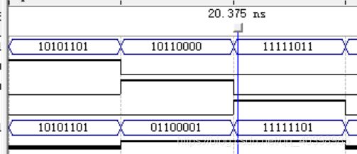
由于该反馈器作用且依赖于于前所有元件的输入端,数据来源复杂庞大,所以此处仿真不予展开。具体仿真波形与下方CPU最终的仿真图形基本一致,可由此进行参考。
四、 系统测试
4.1 测试环境
环境为QuartusII,语言为VHDL。
4.2 测试代码
 顺序为ADD,SUB,OR,NOT,RSR,RSL,MOVE
R1 R2 ,MOVE 11 R2,MOVE R1 11,NOP,(用于过渡NOP的空指令)。
![]()
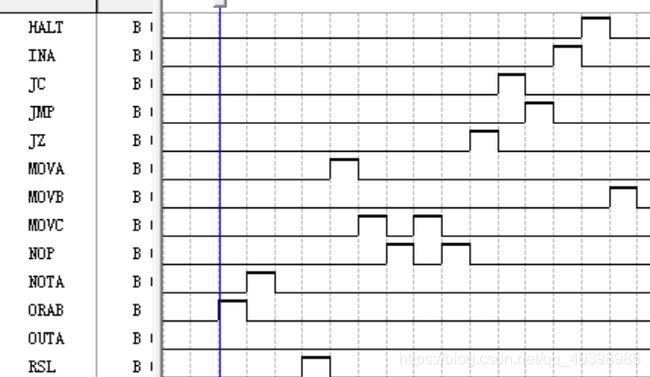
顺序为JMP,(过渡JZ的空指令)JZ,JC,(过渡JC的空指令),IN,OUT,HALT数据存储在mif文件内
4.3 测试结果


五、 总结
本次数电实验难度非常之大,我花了很久的时间才陆陆续续地完成这次实验。所幸平时的实验还是做的挺认真的,所以给这次的实验降低了不少的难度,许多的元器件都是在平时的元件基础上进行修改得出的。但是最难的地方还是在与多个元器件的组合输出,这个之间的各种联系让人费了很多心思。如何调节好时钟周期内各元件的输入与输出是一个很细致的事情,可能错误在于上升下降沿也可能在于信号的赋值。这次实验让我体会到了从简单搭配出发的好处,能很及时地可以发现错误并进行修改,也让我明白了对于波形图仿真验证来讲设置好的数据的重要性所在。虽然这些功能仍比较简陋,但是也确实加深了我对于数电的理解。最让人感觉深刻的经历就是刚开始为了理解CPU的原理花了很久时间,关于哪些是地址哪些是值,传输的路径以及传输时的变化等等,都是花费了大量的时间来思考的。现在看看自己做的CPU,思路感觉比以前要流畅了许多,这也就是这一次实验的魅力所在吧。


