Xilinx LVDS Output——OSERDESE2
Xilinx LVDS Output——OSERDESE2
首先,需要阅读官方提供的使用手册:ug471_7Series_SelectIO.pdf ,Page161 ~ Page173;
先这么理解
LVDS输出,目的是将串行数据,变成时钟频率比较高的串行输出;
可以拆分为两部分:
- 将串行数据的
clock进行倍频; - 将数据排列成倍频之后要输出的顺序;
- 接输出端口,
xdc约束成LVDS输出的电平规格;
读手册
打开手册,翻到161页,可以看到OSERDESE2模块的框图,以及模块的主要信号;
上面为常规8bit的使用框图;该模块最多支持14bit的扩展;
不按照手册上的一句句翻译了,可以说几个吸引眼球的:
- 支持两种并转串的方式
SDR(signal-data rate)和DDR(double-data rate); - 需要两个时钟,
CLK和CLKDIV;CLK为高速串行时钟,CLKDIV为低速分频并行时钟;且二者必须对齐; - 使用之前,必须进行复位;
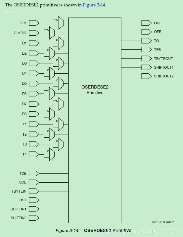
OSERDESE2 Primitive
下图为OSERDESE2的原语示意图:
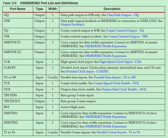
下面是个重点,对上述Port的解释:
后面的手册中,对这些引脚都有详细的介绍,这些引脚的介绍,都比较好理解;咱们还是找几个重要的说;
Reset Input - RST
先看详细介绍:
When asserted, the reset input causes the outputs of all data flip-flops in the CLK and
CLKDIV domains to be driven low asynchronously. When deasserted synchronously with
CLKDIV, internal logic re-times this deassertion to the first rising edge of CLK. Every
OSERDESE2 in a multiple bit output structure should therefore be driven by the same reset
signal, asserted asynchronously, and deasserted synchronously to CLKDIV to ensure that
all OSERDESE2 elements come out of reset in synchronization. The reset signal should
only be deasserted when it is known that CLK and CLKDIV are stable and present.
结论:位信号需要跟CLKDIV同步,且低有效;本案中,使用~ sys_rst_n;
OSERDESE2 Attributes
介绍OSERDESE2模块的属性参数,这个花样比上面说的Port多,见下图属性的总结List:
DATA_RATE_OQ
先看介绍:
The DATA_RATE_OQ attribute defines whether data is processed as single data rate (SDR)
or double data rate (DDR). The allowed values for this attribute are SDR and DDR. The
default value is DDR.
定义输出数据是SDR还是DDR;
DATA_WIDTH
描述:
The DATA_WIDTH attribute defines the parallel data input width of the parallel-to-serial
converter. The possible values for this attribute depend on the DATA_RATE_OQ attribute.
When DATA_RATE_OQ is set to SDR, the possible values for the DATA_WIDTH attribute
are 2, 3, 4, 5, 6, 7, and 8. When DATA_RATE_OQ is set to DDR, the possible values for the
DATA_WIDTH attribute are 4, 6, 8, 10, and 14.
When the DATA_WIDTH is set to widths larger than eight, a pair of OSERDESE2 must be
configured into a master-slave configuration. See OSERDESE2 Width Expansion.
这里使用DDR,参数设置为8;
TRISTATE_WIDTH
这里有一个表格,可以根据前面的使用情况选择:
Clocking Methods
描述:
The phase relationship of CLK and CLKDIV is important in the parallel-to-serial
conversion process. CLK and CLKDIV are (ideally) phase-aligned within a tolerance.
There are several clocking arrangements within the FPGA to help the design meet the
phase relationship requirements of CLK and CLKDIV. The only valid clocking
arrangements for the OSERDESE2 are:
• CLK driven by BUFIO, CLKDIV driven by BUFR
• CLK and CLKDIV driven by CLKOUT[0:6] of the same MMCM or PLL
When using a MMCM to drive the CLK and CLKDIV of the OSERDESE2 the buffer types
suppling the OSERDESE2 can not be mixed. For example, if CLK is driven by a BUFG,
CLKDIV must be driven by a BUFG as well.
第一种,是CLK为BUFIO,CLKDIV为BUFR;对于这二者的解释参考;
第二种,是使用MMCM或PLL的输出时钟;要保证CLK和CLKDIV有同样的buffer类型,不能混(如果CLK是BUFG驱动的,那么CLKDIV也必须是BUFG驱动的);
这里使用的是第二种方式;
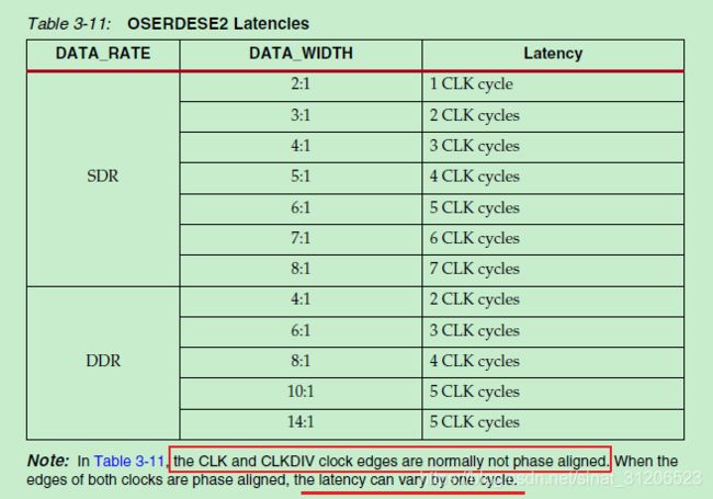
OSERDESE2 Latencies
DATA_RATE和DATA_WIDTH决定了潜伏期为多少,单位为CLK(即为高频时钟),详情见下表:
需要注意红线圈出来的地方,CLK和CLKDIV正常情况下相位不对齐,如果两个时钟的沿对齐了,那么潜伏期就会有一个时钟周期的变化;
时序图
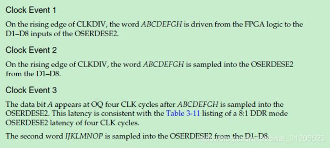
可以根据波形图,来看一下输出潜伏期的周期。
2:1 SDR Serialization
8:1 DDR Serialization
这个波形很清晰的就展示出了,如何将8bit并行输出转为串行输出;
再思考
跟一开始设想的一样,如果连续输入数据1bit:
tx_data0 = {a, b, c, d, e, f, g, h};		// 每个字母代替1bit数据,0或1;
tx_data1 = {i, j, k, l, m, n, o, p};		// 这样比较方便观察;
tx_data2 = {q, r, s, t, u, v, w, x};
就会有输出8bit数据:
ouput0 = {a, i, q};
ouput1 = {b, g, r};
ouput2 = {c, k,s};
ouput3 = {d, l, t};
ouput4 = {e, m, u};
ouput5 = {f, n, v};
ouput6 = {g, o, w};
ouput7 = {h, p, x};
嗯嗯,是想要的样子;仔细阅手册,能获得不少有用的信息。接下来,就是动手用Verilog实现了。
具体方式,下一篇吧。


