ARCore快速入门--使用GLSurfaceView和ARCore绘制3D模型
前言
通过这篇文章读者可以了解:
1. 介绍Android原生代码是如何与ARCore SDK结合在一起使用的
2. ARCore SDK中几个API的功能与使用(主要是Session、Frame、Anchor、Plane)
需知
在读这篇文章之前,读者必须对OpenGL有一定的基础。具体判断自己是否已经掌握了OpenGL的基础,可以根据
以下几个问题来衡量以下,如果是都能快速 清晰的表达出来,则可以继续进行阅读了
- Android的SurfaceView有两种渲染模式,是哪两种以及区别是什么
- OpenGL的绘制流程是什么
- GLSL是什么
- vertex shader和fragment shader的作用分别是什么
知识点
- 如何使用GLSurfaceView绘制
- 如何使用ARCore绘制出系统Camera Preview到GLSurfaceView
- 如何绘制Virtual Object到用户的点击位置
接下来我们就一步一步的实现文章顶部所展示的效果图功能
添加并初始化GLSurfaceView
创建布局xml文件 activity_my_first_ar.xml。如下所示:
<RelativeLayout xmlns:android="http://schemas.android.com/apk/res/android"
    android:layout_width="match_parent"
    android:layout_height="match_parent">

    <android.opengl.GLSurfaceView
        android:id="@+id/glSurfaceView"
        android:layout_width="match_parent"
        android:layout_height="match_parent" />

RelativeLayout>
然后在 MyFirstArActivity.java 中初始化 GLSurfaceView
// 初始化GLSurfaceView
        surfaceView = findViewById(R.id.glSurfaceView);

        // 配置GLSurfaceView基本属性, 并设置renderer.
        surfaceView.setPreserveEGLContextOnPause(true);
        surfaceView.setEGLContextClientVersion(2);
        surfaceView.setEGLConfigChooser(8, 8, 8, 8, 16, 0); // Alpha used for plane blending.
        surfaceView.setRenderer(this);
        surfaceView.setRenderMode(GLSurfaceView.RENDERMODE_CONTINUOUSLY);
因为将 this 传递给了 setRenderer 方法, 因此需要将 MyFirstArActivity.java 实现 GLSurfaceView.Renderer 接口.
并实现接口的抽象方法
public class MyFirstArActivity extends AppCompatActivity implements GLSurfaceView.Renderer {
@Override
public void onSurfaceCreated(GL10 gl, EGLConfig config) {
GLES20.glClearColor(1f, 0f, 0f, 1.0f);
}
@Override
public void onSurfaceChanged(GL10 gl, int width, int height) {
GLES20.glViewport(0, 0, width, height);
}
@Override
public void onDrawFrame(GL10 gl) {
GLES20.glClear(GLES20.GL_COLOR_BUFFER_BIT | GLES20.GL_DEPTH_BUFFER_BIT);
}
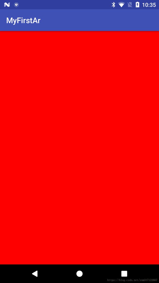
}上述代码中,通过在 onSurfaceCreated 方法中使用 GLES20.glClearColor(1f, 0f, 0f, 1.0f); 这行代码
绘制了一个红色背景。代码到目前为止 GLSurfaceView的基本初始化与配置就已经完成了,看一下运行效果
截止目前的代码可以查看工程的 SurfaceView 分支: https://github.com/McoyJiang/FirstArDemo/tree/SurfaceView
使用ARCore绘制出系统Camera Preview到GLSurfaceView
了解了如何使用GLSurfaceView之后,接下来看一下如何使用ARCore SDK将Camera视图绘制到SurfaceView上。
在这之前需要先对ARCore中的几个API简单描述一下
Session
这个类是ARCore中最重要的一个类,先看一下官方对它的一些介绍
Manages AR system state and handles the session lifecycle. This class is the main entry point to ARCore API. This class allows the user to create a session, configure it, start/stop it, and most importantly receive frames that allow access to camera image and device pose
简单翻译一下:Session管理者AR系统的状态和生命周期. Session是ARCore的入口,用户通过它来创建、配置一个AR场景,或者是启动、停止AR。Session还有一个最重要的功能就是通过Session可以获取Camera的当前帧(Frame), 只要拿到Frame我们就可以访问Camera中的数据
Frame
刚才说了通过Session可以拿到当前帧(Frame), 而这个Frame内部就是封装了Camera的状态已经数据。它有个很重要的方法 getCamera() 返回的就是AR Session所请求到的设备Camera对象。有了Camera之后,就可以通过这个Camera的 getProjectionMatrix 和 getViewMatrix 方法分别初始化ProjectMatrix和ViewMatrix了。而这两个Matrix都是OpenGL绘制时所需要的
了解了这两个类的定义与作用之后,先来看一张ARCore使用简单流程图

简单说明一下:
第一步:一般情况下在Activity的 onCreate 方法中对Session进行创建工作,在 onResume 方法中调用 Session.resume 方法。上图省略了 直接统一在 onCreate 方法中执行了
第二步:在 GLSurfaceView.Renderer 的回调方法 onDrawFrame 中通过调用 Session.update 方法获取 Frame 对象, 然后调用OpenGL的相关方法将Frame绘制到GLSurfaceView上。 这期间有一步非常关键的一步就是调用 frame.transformDisplayUvCoords(quadTexCoord, quadTexCoordTransformed); 这行代码。作用是设置显示Frame的 UV Coordinates(也有叫Texture Coordinates或UV Mapping的)。对UV Coordinates不明白的可以参考维基百科对它的解释https://en.wikipedia.org/wiki/UV_mapping
接下来就看一下代码中的具体实现
首先在 MyFirstArActivity 的 onResume 和 onPause 中添加如下代码
    @Override
    protected void onResume() {
        super.onResume();

        //申请Camera权限的操作
        。。。

        try {
            session = new Session(/* context= */ this);
            session.resume();
        } catch (CameraNotAvailableException e) {
            // 有些情况下,手机Camera正在被其它的App所使用。这种情况下可能会报Camera Not Available异常
            session = null;
            return;
        }

        surfaceView.onResume();
    }

@Override
    public void onPause() {
        super.onPause();
        if (session != null) {
            // 注意:顺序不能改变!必须先暂停GLSurfaceView, 否则GLSurfaceView会继续调用Session的update方法。
            // 但是Session已经pause状态,所以会报SessionPausedException异常
            surfaceView.onPause();
            session.pause();
        }
    }
因为Session需要申请操作系统的Camera摄像头,因此可定需要做一些Camera权限申请的操作,在此处不是讲解的重点所以省略了。
另外在 onPause 中 SurfaceView 和Session 调用pause的顺序不能改变,原因已经写在注释中了.
接下来在 onSurfaceCreated 方法中添加绘制背景Camera视图的Renderer对象
    @Override
    public void onSurfaceCreated(GL10 gl, EGLConfig config) {
        GLES20.glClearColor(0.1f, 0.1f, 0.1f, 1.0f);

        try {
            // 初始化用来画背景以及Virtual Object的OpenGL设置
            // 主要包括各种OpenGL需要使用的textureId, Texture Coordinates, Shader, Program等
            backgroundRenderer.createOnGlThread(this);
        } catch (IOException e) {
            Log.e(TAG, "Failed to read an asset file", e);
        }
    }
需要说明一下,这里为什么会多出一个 backgroundRenderer 对象。因为一会我们需要在onDrawFrame方法中,
写大量的OpenGL代码来绘制Frame对象的内容,但是出于代码重构中 Feature Envy(特性嫉妒) 的原则,我们
最好将这大量的代码封装在一个DATA类中,这就是BackGroundRenderer的来历。在代码结构中的位置如下图所示:

BackgroundRenderer.createOnGlThread方法具体如下:
public void createOnGlThread(Context context) throws IOException {
    // Generate the background texture.
    int[] textures = new int[1];
    GLES20.glGenTextures(1, textures, 0);
    textureId = textures[0];
    int textureTarget = GLES11Ext.GL_TEXTURE_EXTERNAL_OES;
    GLES20.glBindTexture(textureTarget, textureId);
    GLES20.glTexParameteri(textureTarget, GLES20.GL_TEXTURE_WRAP_S, GLES20.GL_CLAMP_TO_EDGE);
    GLES20.glTexParameteri(textureTarget, GLES20.GL_TEXTURE_WRAP_T, GLES20.GL_CLAMP_TO_EDGE);
    GLES20.glTexParameteri(textureTarget, GLES20.GL_TEXTURE_MIN_FILTER, GLES20.GL_NEAREST);
    GLES20.glTexParameteri(textureTarget, GLES20.GL_TEXTURE_MAG_FILTER, GLES20.GL_NEAREST);

    int numVertices = 4;
    if (numVertices != QUAD_COORDS.length / COORDS_PER_VERTEX) {
      throw new RuntimeException("Unexpected number of vertices in BackgroundRenderer.");
    }

    ByteBuffer bbVertices = ByteBuffer.allocateDirect(QUAD_COORDS.length * FLOAT_SIZE);
    bbVertices.order(ByteOrder.nativeOrder());
    quadVertices = bbVertices.asFloatBuffer();
    quadVertices.put(QUAD_COORDS);
    quadVertices.position(0);

    ByteBuffer bbTexCoords =
        ByteBuffer.allocateDirect(numVertices * TEXCOORDS_PER_VERTEX * FLOAT_SIZE);
    bbTexCoords.order(ByteOrder.nativeOrder());
    quadTexCoord = bbTexCoords.asFloatBuffer();
    quadTexCoord.put(QUAD_TEXCOORDS);
    quadTexCoord.position(0);

    ByteBuffer bbTexCoordsTransformed =
        ByteBuffer.allocateDirect(numVertices * TEXCOORDS_PER_VERTEX * FLOAT_SIZE);
    bbTexCoordsTransformed.order(ByteOrder.nativeOrder());
    quadTexCoordTransformed = bbTexCoordsTransformed.asFloatBuffer();

    int vertexShader =
        ShaderUtil.loadGLShader(TAG, context, GLES20.GL_VERTEX_SHADER, VERTEX_SHADER_NAME);
    int fragmentShader =
        ShaderUtil.loadGLShader(TAG, context, GLES20.GL_FRAGMENT_SHADER, FRAGMENT_SHADER_NAME);

    quadProgram = GLES20.glCreateProgram();
    GLES20.glAttachShader(quadProgram, vertexShader);
    GLES20.glAttachShader(quadProgram, fragmentShader);
    GLES20.glLinkProgram(quadProgram);
    GLES20.glUseProgram(quadProgram);

    ShaderUtil.checkGLError(TAG, "Program creation");

    quadPositionParam = GLES20.glGetAttribLocation(quadProgram, "a_Position");
    quadTexCoordParam = GLES20.glGetAttribLocation(quadProgram, "a_TexCoord");

    ShaderUtil.checkGLError(TAG, "Program parameters");
  }
都是一些OpenGL初始化的相关操作,就不做过多介绍了。
最后只要在 onDrawFrame 方法中,添加如下几行代码
@Override
    public void onDrawFrame(GL10 gl) {
        GLES20.glClear(GLES20.GL_COLOR_BUFFER_BIT | GLES20.GL_DEPTH_BUFFER_BIT);

        if (session == null) {
            return;
        }

        try {
            // 将在'createOnGlThread'方法中已经初始化好的Texture Handle(句柄)传给AR Session
            // 如果没有设置此句柄,则会显示黑屏。
            session.setCameraTextureName(backgroundRenderer.getTextureId());

            // 通过AR Session获取当前手机摄像头(Camera)的当前帧(Frame)。
            Frame frame = session.update();

            // 将当前帧Frame当做背景来draw到SurfaceView上,因此我们能在手机屏幕上看到摄像头中的实时内容
            backgroundRenderer.draw(frame);
        } catch (Exception e) {

        }
    }
需要注意的就是需要先将BackgroundRenderer的Texture句柄传递给Session,这样AR Session才知道绘制到哪里。backgroundRenderer.draw 的实现如下
  public void draw(Frame frame) {
    // If display rotation changed (also includes view size change), we need to re-query the uv
    // coordinates for the screen rect, as they may have changed as well.
    if (frame.hasDisplayGeometryChanged()) {
      frame.transformDisplayUvCoords(quadTexCoord, quadTexCoordTransformed);
    }

    // No need to test or write depth, the screen quad has arbitrary depth, and is expected
    // to be drawn first.
    GLES20.glDisable(GLES20.GL_DEPTH_TEST);
    GLES20.glDepthMask(false);

    GLES20.glBindTexture(GLES11Ext.GL_TEXTURE_EXTERNAL_OES, textureId);

    GLES20.glUseProgram(quadProgram);

    // Set the vertex positions.
    GLES20.glVertexAttribPointer(
        quadPositionParam, COORDS_PER_VERTEX, GLES20.GL_FLOAT, false, 0, quadVertices);

    // Set the texture coordinates.
    GLES20.glVertexAttribPointer(
        quadTexCoordParam,
        TEXCOORDS_PER_VERTEX,
        GLES20.GL_FLOAT,
        false,
        0,
        quadTexCoordTransformed);

    // Enable vertex arrays
    GLES20.glEnableVertexAttribArray(quadPositionParam);
    GLES20.glEnableVertexAttribArray(quadTexCoordParam);

    GLES20.glDrawArrays(GLES20.GL_TRIANGLE_STRIP, 0, 4);

    // Disable vertex arrays
    GLES20.glDisableVertexAttribArray(quadPositionParam);
    GLES20.glDisableVertexAttribArray(quadTexCoordParam);

    // Restore the depth state for further drawing.
    GLES20.glDepthMask(true);
    GLES20.glEnable(GLES20.GL_DEPTH_TEST);

    ShaderUtil.checkGLError(TAG, "Draw");
  }
前面已经介绍过了,这个方法中最重要的就是需要调用 frame.transformDisplayUvCoords(quadTexCoord, quadTexCoordTransformed);这行代码。这是设置Frame的UV Coordinate, 将2D事物转为话一个3D的坐标系统。
代码运行到这里,我们就已经实现了将Camera的视图给实时绘制在GLSurfaceView上显示了,效果图如下:
截止目前的代码可以参考 AR_Show_CameraView 分支上的代码https://github.com/McoyJiang/FirstArDemo/tree/AR_Show_CameraView