ESP32学习笔记(4)——UART串口使用
一、概述
通用异步收发送器(UART)是一种硬件特性,它使用广泛适应的异步串行通信接口(如RS 232、RS 422、RS 485)来处理通信(即时序要求和数据帧)。UART提供了一种广泛采用和廉价的方法来实现不同设备之间的全双工或半双工数据交换。
ESP 32芯片有三个UART控制器(UART 0、UART 1和UART 2),它们具有一组相同的寄存器,以便于编程和灵活性。
每个UART控制器都是独立配置的,参数包括波特率、数据比特长度、位序、停止位数、奇偶校验位等。所有控制器都与不同厂商的UART支持设备兼容,还可以支持红外数据关联协议(IRDA)。
ESP-IDF 编程指南——UART
二、API说明
以下 UART 接口位于 driver/include/driver/uart.h。
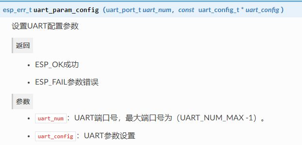
2.1 uart_param_config
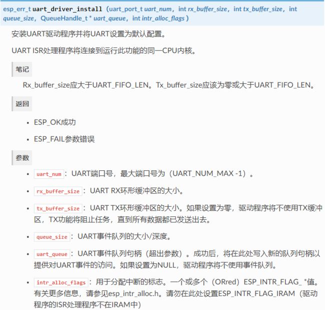
2.2 uart_driver_install
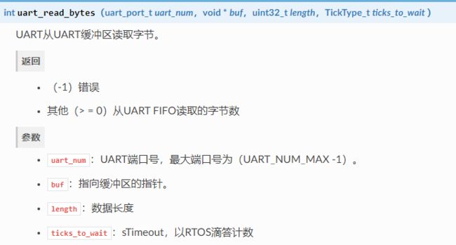
2.3 uart_read_bytes
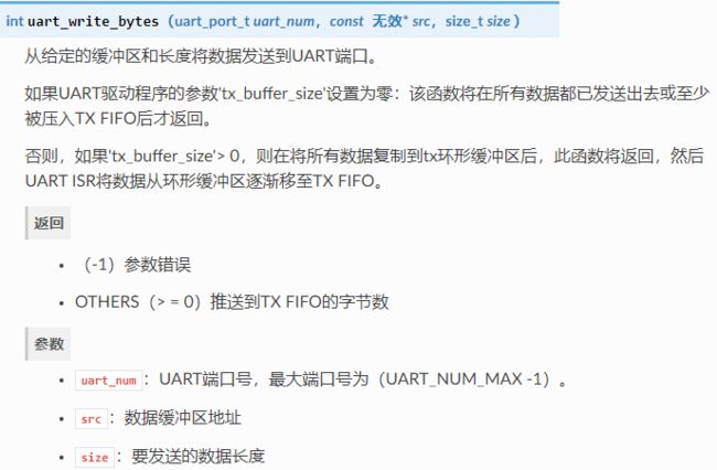
2.4 uart_write_bytes
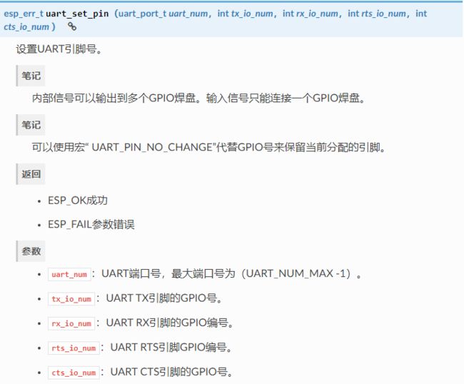
2.5 uart_set_pin
ESP32的串口是支持引脚映射的,比如我的开发板串口一默认的是GPIO9和GPIO10,现在将TX、RX映射到GPIO4和GPIO5上。
三、编程流程
3.1 设置通信参数
如设置波特率、数据位、停止位等
在结构体中进行配置:
typedef struct {

    int baud_rate;                      /*!< UART baud rate*/
    uart_word_length_t data_bits;       /*!< UART byte size*/
    uart_parity_t parity;               /*!< UART parity mode*/
    uart_stop_bits_t stop_bits;         /*!< UART stop bits*/
    uart_hw_flowcontrol_t flow_ctrl;    /*!< UART HW flow control mode (cts/rts)*/
    uint8_t rx_flow_ctrl_thresh;        /*!< UART HW RTS threshold*/
    union {

        uart_sclk_t source_clk;         /*!< UART source clock selection */
        bool use_ref_tick  __attribute__((deprecated)); /*!< Deprecated method to select ref tick clock source, set source_clk field instead */
    };
} uart_config_t;
3.2 设置通信引脚
ESP32的串口是支持引脚映射的,比如我的开发板串口一默认的是GPIO9和GPIO10,现在将TX、RX映射到GPIO4和GPIO5上。
请调用函数uart_set_pin()并指定驱动程序应将Tx,Rx,RTS和CTS信号路由至的GPIO引脚号。
如果要为特定信号保留当前分配的管脚号,请传递宏UART_PIN_NO_CHANGE。
应该为不使用的引脚指定相同的宏。
// Set UART pins(TX: IO17 (UART2 default), RX: IO16 (UART2 default), RTS: IO18, CTS: IO19)
ESP_ERROR_CHECK(uart_set_pin(UART_NUM_2, UART_PIN_NO_CHANGE, UART_PIN_NO_CHANGE, 18, 19));
3.3 驱动程序安装
设置好通信引脚后,通过调用安装驱动程序uart_driver_install()并指定以下参数:
- Tx环形缓冲区的大小
- Rx环形缓冲区的大小
- 事件队列句柄和大小
- 分配中断的标志
该功能将为UART驱动程序分配所需的内部资源。
// Setup UART buffered IO with event queue
const int uart_buffer_size = (1024 * 2);
QueueHandle_t uart_queue;
// Install UART driver using an event queue here
ESP_ERROR_CHECK(uart_driver_install(UART_NUM_2, uart_buffer_size, \
                                        uart_buffer_size, 10, &uart_queue, 0));
3.4 运行UART通信
串行通信由每个UART控制器的有限状态机(FSM)控制。
发送数据的过程涉及以下步骤:
- 将数据写入Tx FIFO缓冲区
- FSM序列化数据
- FSM将数据发送出去
接收数据的过程类似,但是步骤相反:
- FSM处理传入的串行流并将其并行化
- FSM将数据写入Rx FIFO缓冲区
- 从Rx FIFO缓冲区读取数据
因此,应用程序将被限制为分别使用uart_write_bytes()和从相应的缓冲区写入和读取数据uart_read_bytes(),而FSM将完成其余的工作。
3.4.1 发送
准备好要传输的数据后,调用该函数uart_write_bytes()并将数据缓冲区的地址和数据长度传递给该函数。该函数将数据复制到Tx环形缓冲区(立即或在有足够空间可用之后),然后退出。当Tx FIFO缓冲区中有可用空间时,中断服务程序(ISR)将数据从Tx环形缓冲区移至后台的Tx FIFO缓冲区。下面的代码演示了此功能的用法。
// Write data to UART.
char* test_str = "This is a test string.\n";
uart_write_bytes(uart_num, (const char*)test_str, strlen(test_str));
该功能uart_write_bytes_with_break()类似于uart_write_bytes()但在传输结束时添加了一个串行中断信号。意味着它会在发送完数据之后,设置TX低电平一段时间(RTOS任务节拍为单位)。
// Write data to UART, end with a break signal.
uart_write_bytes_with_break(uart_num, "test break\n",strlen("test break\n"), 100);
将数据写入Tx FIFO缓冲区的另一个功能是uart_tx_chars()。不像uart_write_bytes(),此功能在可用空间之前不会阻塞。相反,它将写入可立即放入硬件Tx FIFO中的所有数据,然后返回已写入的字节数。
有一个“陪伴”功能uart_wait_tx_done(),可监视Tx FIFO缓冲区的状态并在其为空时返回。
// Wait for packet to be sent
const int uart_num = UART_NUM_2;
ESP_ERROR_CHECK(uart_wait_tx_done(uart_num, 100)); // wait timeout is 100 RTOS ticks (TickType_t)
3.4.2 接收
UART接收到数据并将其保存在Rx FIFO缓冲区后,需要使用函数进行读出uart_read_bytes()。,这个函数会阻塞待在那里,直到读满需要的字节,或是超时。
在读取数据之前,您可以调用来检查Rx FIFO缓冲区中可用的字节数uart_get_buffered_data_len(),然后再读取相应的内容,这样就不会造成不必要的阻塞。下面给出了使用这些功能的示例。
// Read data from UART.
const int uart_num = UART_NUM_2;
uint8_t data[128];
int length = 0;
ESP_ERROR_CHECK(uart_get_buffered_data_len(uart_num, (size_t*)&length));
length = uart_read_bytes(uart_num, data, length, 100);
如果不再需要Rx FIFO缓冲区中的数据,则可以通过调用清除缓冲区uart_flush()。
四、串口回环输出
这里我将GPIO4、GPIO5改成了GPIO23、GPIO18
#include 五、串口队列接收
/*********************************************************************
* INCLUDES
*/
#include 六、UART1打印日志
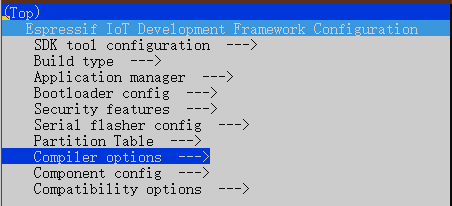
在 ESP-IDF 中任何例程中输入idf.py menuconfig
选择 Component config
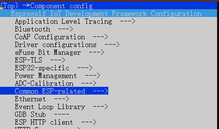
选择 Common ESP-related
选择 UART for console output
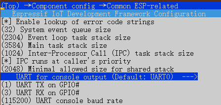
从默认串口0改为 Custom

选择 UART peripheral to use for console output 改为 UART1 输出
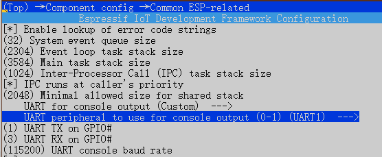
将 UART TX on GPIO 和 UART RX on GPIO 改为你想要的引脚
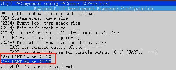
修改完后,变成UART1打印日志

• 由 Leung 写于 2021 年 4 月 16 日
• 参考:[ESP32]UART串口使用
ESP32 ESP-IDF UART使用模式检测中断报告事件实现 收发数据