Arduino ESP32-CAM 学习之旅② ESP32-CAM开发板
文章目录
-
- 基于Arduino的ESP32-CAM开发技术全系列教程
- 1. 前言
- 2.开发板
-
- 2.1 CAMERA_MODEL_WROVER_KIT
- 2.2 CAMERA_MODEL_ESP_EYE(Espressif)
- 2.3 CAMERA_MODEL_M5STACK_PSRAM
- 2.4 CAMERA_MODEL_M5STACK_WIDE
- 2.5 CAMERA_MODEL_AI_THINKER
- 2.6 CAMERA_MODEL_TTGO_T_JOURNAL
基于Arduino的ESP32-CAM开发技术全系列教程
1. 前言
在上一讲中,我们最后运行了一个例子。

#include "esp_camera.h"
#include 我们需要关注一个点就是摄像头模块:
// Select camera model
//#define CAMERA_MODEL_WROVER_KIT // Has PSRAM
//#define CAMERA_MODEL_ESP_EYE // Has PSRAM
//#define CAMERA_MODEL_M5STACK_PSRAM // Has PSRAM
//#define CAMERA_MODEL_M5STACK_WIDE	// Has PSRAM
#define CAMERA_MODEL_AI_THINKER // Has PSRAM
//#define CAMERA_MODEL_TTGO_T_JOURNAL // No PSRAM
国内默认情况下我们是使用 CAMERA_MODEL_AI_THINKER ,也就是安信可摄像头模块。
不同的摄像头模块引脚定义不一样,但是最终对外暴露统一的宏 (camera_pins.h)。
#if defined(CAMERA_MODEL_WROVER_KIT)
#define PWDN_GPIO_NUM    -1
#define RESET_GPIO_NUM   -1
#define XCLK_GPIO_NUM    21
#define SIOD_GPIO_NUM    26
#define SIOC_GPIO_NUM    27

#define Y9_GPIO_NUM      35
#define Y8_GPIO_NUM      34
#define Y7_GPIO_NUM      39
#define Y6_GPIO_NUM      36
#define Y5_GPIO_NUM      19
#define Y4_GPIO_NUM      18
#define Y3_GPIO_NUM       5
#define Y2_GPIO_NUM       4
#define VSYNC_GPIO_NUM   25
#define HREF_GPIO_NUM    23
#define PCLK_GPIO_NUM    22

#elif defined(CAMERA_MODEL_ESP_EYE)
#define PWDN_GPIO_NUM    -1
#define RESET_GPIO_NUM   -1
#define XCLK_GPIO_NUM    4
#define SIOD_GPIO_NUM    18
#define SIOC_GPIO_NUM    23

#define Y9_GPIO_NUM      36
#define Y8_GPIO_NUM      37
#define Y7_GPIO_NUM      38
#define Y6_GPIO_NUM      39
#define Y5_GPIO_NUM      35
#define Y4_GPIO_NUM      14
#define Y3_GPIO_NUM      13
#define Y2_GPIO_NUM      34
#define VSYNC_GPIO_NUM   5
#define HREF_GPIO_NUM    27
#define PCLK_GPIO_NUM    25

#elif defined(CAMERA_MODEL_M5STACK_PSRAM)
#define PWDN_GPIO_NUM     -1
#define RESET_GPIO_NUM    15
#define XCLK_GPIO_NUM     27
#define SIOD_GPIO_NUM     25
#define SIOC_GPIO_NUM     23

#define Y9_GPIO_NUM       19
#define Y8_GPIO_NUM       36
#define Y7_GPIO_NUM       18
#define Y6_GPIO_NUM       39
#define Y5_GPIO_NUM        5
#define Y4_GPIO_NUM       34
#define Y3_GPIO_NUM       35
#define Y2_GPIO_NUM       32
#define VSYNC_GPIO_NUM    22
#define HREF_GPIO_NUM     26
#define PCLK_GPIO_NUM     21

#elif defined(CAMERA_MODEL_M5STACK_WIDE)
#define PWDN_GPIO_NUM     -1
#define RESET_GPIO_NUM    15
#define XCLK_GPIO_NUM     27
#define SIOD_GPIO_NUM     22
#define SIOC_GPIO_NUM     23

#define Y9_GPIO_NUM       19
#define Y8_GPIO_NUM       36
#define Y7_GPIO_NUM       18
#define Y6_GPIO_NUM       39
#define Y5_GPIO_NUM        5
#define Y4_GPIO_NUM       34
#define Y3_GPIO_NUM       35
#define Y2_GPIO_NUM       32
#define VSYNC_GPIO_NUM    25
#define HREF_GPIO_NUM     26
#define PCLK_GPIO_NUM     21

#elif defined(CAMERA_MODEL_AI_THINKER)
#define PWDN_GPIO_NUM     32
#define RESET_GPIO_NUM    -1
#define XCLK_GPIO_NUM      0
#define SIOD_GPIO_NUM     26
#define SIOC_GPIO_NUM     27

#define Y9_GPIO_NUM       35
#define Y8_GPIO_NUM       34
#define Y7_GPIO_NUM       39
#define Y6_GPIO_NUM       36
#define Y5_GPIO_NUM       21
#define Y4_GPIO_NUM       19
#define Y3_GPIO_NUM       18
#define Y2_GPIO_NUM        5
#define VSYNC_GPIO_NUM    25
#define HREF_GPIO_NUM     23
#define PCLK_GPIO_NUM     22

#elif defined(CAMERA_MODEL_TTGO_T_JOURNAL)
#define PWDN_GPIO_NUM      0
#define RESET_GPIO_NUM    15
#define XCLK_GPIO_NUM     27
#define SIOD_GPIO_NUM     25
#define SIOC_GPIO_NUM     23

#define Y9_GPIO_NUM       19
#define Y8_GPIO_NUM       36
#define Y7_GPIO_NUM       18
#define Y6_GPIO_NUM       39
#define Y5_GPIO_NUM        5
#define Y4_GPIO_NUM       34
#define Y3_GPIO_NUM       35
#define Y2_GPIO_NUM       17
#define VSYNC_GPIO_NUM    22
#define HREF_GPIO_NUM     26
#define PCLK_GPIO_NUM     21

#else
#error "Camera model not selected"
#endif
这里分别定义了几种常用摄像头模块,超出这些范围的,需要自己自定义映射。
- CAMERA_MODEL_WROVER_KIT
- CAMERA_MODEL_ESP_EYE
- CAMERA_MODEL_M5STACK_PSRAM
- CAMERA_MODEL_M5STACK_WIDE
- CAMERA_MODEL_AI_THINKER
- CAMERA_MODEL_TTGO_T_JOURNAL
https://diyprojects.io/esp32-cam-pins-and-equipment-esp-eye-ai-thinker-ttgo-t-camera-m5stack-timer-camera/#.YKRdsshLE6g
2.开发板
Even though all ESP32-CAM development boards share the
same C ++ (Arduino) code, each manufacturer has connected the camera module to the pins of the ESP32 differently. This article summarizes the pinout of the main ESP32-CAM development boards currently available. ESP-EYE by Espressif, ESP32-CAM Ai Thinker, M5Stack Timer Camera, TTGO T-Camera, T-Camera Plus and T-Journal.
2.1 CAMERA_MODEL_WROVER_KIT
暂时没找到。。。
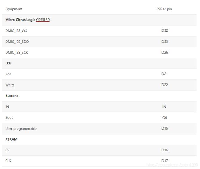
2.2 CAMERA_MODEL_ESP_EYE(Espressif)


The ESP-EYE is equipped with an ESP32 chip (ESP32-D0WD version), a 3D WiFi antenna of a 2MP camera, a Cirrus Logic CS53L30 microphone, 2 LEDs (red and white), 8Mo of PSRAM usable to increase the RAM of the ESP32 and 4MB of flash memory (program and user data storage). Programming is done via a micro USB connector.
引脚映射(Pins assigned to the OmniVision OV2640, OV3660 or OV5640 camera module.):
#define PWDN_GPIO_NUM    -1
#define RESET_GPIO_NUM   -1
#define XCLK_GPIO_NUM    4
#define SIOD_GPIO_NUM    18
#define SIOC_GPIO_NUM    23

#define Y9_GPIO_NUM      36
#define Y8_GPIO_NUM      37
#define Y7_GPIO_NUM      38
#define Y6_GPIO_NUM      39
#define Y5_GPIO_NUM      35
#define Y4_GPIO_NUM      14
#define Y3_GPIO_NUM      13
#define Y2_GPIO_NUM      34
#define VSYNC_GPIO_NUM   5
#define HREF_GPIO_NUM    27
#define PCLK_GPIO_NUM    25
2.3 CAMERA_MODEL_M5STACK_PSRAM
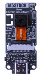
The M5Stack Timer Camera has
8MBof PSRAM, an OmniVisionOV3660sensor equipped with a lens with a field of view of 66.5 ° which offers a resolution of 2048×1536 pixels, an RTC clock (BM8563), a PH2.0- connector. 4P (Grove connector), a white LED (IO2) and a connector for LiPo battery. The battery charge can be measured on the pin (IO33)
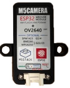
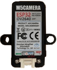
而在demo中,这个对应了 M5Camera, model A
#define PWDN_GPIO_NUM     -1
#define RESET_GPIO_NUM    15
#define XCLK_GPIO_NUM     27
#define SIOD_GPIO_NUM     25
#define SIOC_GPIO_NUM     23
#define Y9_GPIO_NUM       19
#define Y8_GPIO_NUM       36
#define Y7_GPIO_NUM       18
#define Y6_GPIO_NUM       39
#define Y5_GPIO_NUM        5
#define Y4_GPIO_NUM       34
#define Y3_GPIO_NUM       35
#define Y2_GPIO_NUM       32
#define VSYNC_GPIO_NUM    22
#define HREF_GPIO_NUM     26
#define PCLK_GPIO_NUM     21
2.4 CAMERA_MODEL_M5STACK_WIDE
对应 M5Camera model B,
#define PWDN_GPIO_NUM     -1
#define RESET_GPIO_NUM    15
#define XCLK_GPIO_NUM     27
#define SIOD_GPIO_NUM     22
#define SIOC_GPIO_NUM     23
#define Y9_GPIO_NUM       19
#define Y8_GPIO_NUM       36
#define Y7_GPIO_NUM       18
#define Y6_GPIO_NUM       39
#define Y5_GPIO_NUM        5
#define Y4_GPIO_NUM       34
#define Y3_GPIO_NUM       35
#define Y2_GPIO_NUM       32
#define VSYNC_GPIO_NUM    25
#define HREF_GPIO_NUM     26
#define PCLK_GPIO_NUM     21
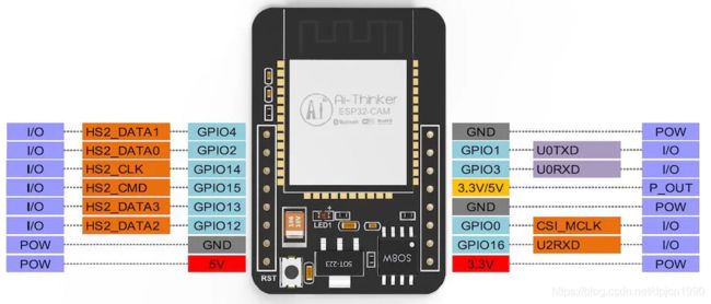
2.5 CAMERA_MODEL_AI_THINKER
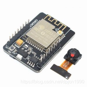
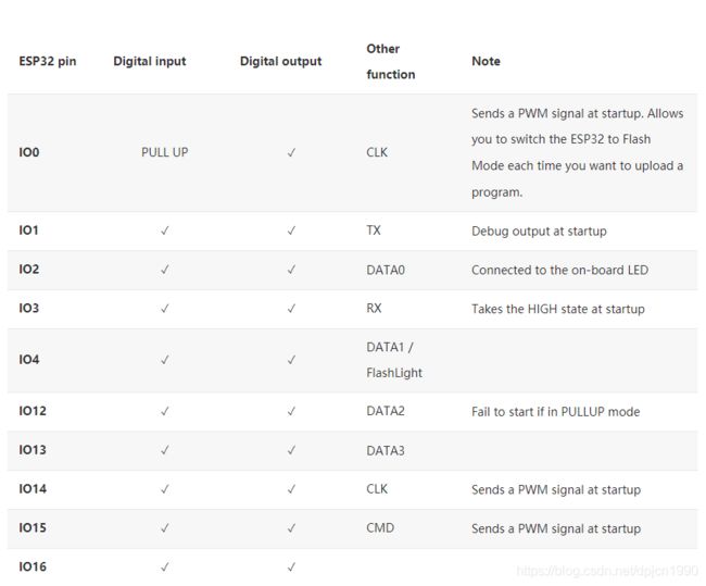
- Pins 2 4 12 13 14 and 15 are shared with the
micro SD card reader. Therefore, it is strongly advised not to use these pins for any other purpose if you want to store pictures or videos.- Pins 2 4 12 13 14 and 15 are RTC compatible and support the Analog to Digital Converter (
ADC) of the ESP32.
If your application uses the micro SD card reader, only pins 2 3 and 16 are available. However, the following constraints must be taken into account:
- The
GPIO16pin not being RTC, it will not be possible to wake up the ESP32-CAM using a PIR motion detector for example.- You will need to make pins 1 and 3 (
RX / TX serial port) available each time you need to update the program. By integrating wireless update (OTA), you can downsize to one time.
闪光灯(Flash Light, LED lighting):
A white lighting LED is connected to the
IO4pin of the ESP32. You can use it as an accent light only if you are not using the micro SD card to store photos or videos.
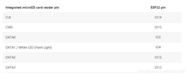
sd卡引脚映射(Pin identification of the micro SD card reader):
The
IO4pin is shared between the white LED and theDATA1pin of the integrated microSD card reader. This causes the LED to blink with each write to the SD card.
引脚映射(Pins assigned to the OmniVision OV2640, OV3660 or OV5640 camera module.):
#define PWDN_GPIO_NUM 32
#define RESET_GPIO_NUM -1
#define XCLK_GPIO_NUM 0
#define SIOD_GPIO_NUM 26
#define SIOC_GPIO_NUM 27
#define Y9_GPIO_NUM 35
#define Y8_GPIO_NUM 34
#define Y7_GPIO_NUM 39
#define Y6_GPIO_NUM 36
#define Y5_GPIO_NUM 21
#define Y4_GPIO_NUM 19
#define Y3_GPIO_NUM 18
# define Y2_GPIO_NUM 5
#define VSYNC_GPIO_NUM 25
#define HREF_GPIO_NUM 23
#define PCLK_GPIO_NUM 22
2.6 CAMERA_MODEL_TTGO_T_JOURNAL
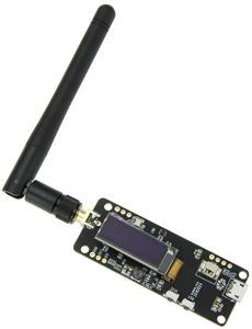
- The TTGO T-Journal is directly fitted with an SMA connector. An IPEX connector (uFL) is also present at the base of the SMA connector. Good idea ! No antenna is engraved on the PCB, so you must
use an external antenna.- Pins 2, 4, 14 and 13 as well as the 3.3V and GND power pins are exposed on the board. You will need to solder a 2.54mm pitch connector directly to the board. The holes are already pre-drilled.
Pins assigned to the OmniVision OV2640 camera module.
#define PWDN_GPIO_NUM     32
#define RESET_GPIO_NUM    -1
#define XCLK_GPIO_NUM     27
#define SIOD_GPIO_NUM     25
#define SIOC_GPIO_NUM     23
#define Y9_GPIO_NUM       19
#define Y8_GPIO_NUM       36
#define Y7_GPIO_NUM       18
#define Y6_GPIO_NUM       39
#define Y5_GPIO_NUM       5
#define Y4_GPIO_NUM       34
#define Y3_GPIO_NUM       35
#define Y2_GPIO_NUM       17
#define VSYNC_GPIO_NUM    22
#define HREF_GPIO_NUM     26
#define PCLK_GPIO_NUM     21