ESP32学习笔记(20)——SPI(从机)接口使用

一、SPI简介

SPI(Serial Peripheral Interface) 协议是由摩托罗拉公司提出的通讯协议,即串行外围设备接口,是一种高速全双工的通信总线。它被广泛地使用在 ADC、LCD 等设备与 MCU 间,要求通讯速率较高的场合。

芯片的管脚上只占用四根线。
MISO: 主器件数据输出,从器件数据输入。
MOSI:主器件数据输入,从器件数据输出。
SCK: 时钟信号,由主设备控制发出。
NSS(CS): 从设备选择信号,由主设备控制。当NSS为低电平则选中从器件。

1.1 ESP32中SPI

ESP32集成了两个通用SPI控制器,可用作片外SPI主设备驱动的从节点

  • SPI2,有时也称为HSPI
  • SPI3,有时也称为VSPI
    SPI2和SPI3具有独立的信号总线,分别具有相同的名称。

SPI从驱动程序允许将SPI外设用作全双工设备。驱动程序可以发送/接收最长64个字节的数据,或者使用DMA发送/接收更长的数据。但是,存在一些与DMA相关的已知问题。

  • 启用DMA时应当将收发缓存设定为字对齐模式(是4字节的倍数)。
  • 从机模式的DMA需要主机时钟的保持时间足够长才能工作,如果主机无法满足只能放弃使用DMA。

ESP-IDF 编程指南——SPI从驱动

1.2 SPI传输

当主机置位CS线并开始在SCLK线上发送时钟脉冲时,将开始全双工SPI传输。每个时钟脉冲,数据位都从主机移到MOSI线上的设备,同时又移回到MISO线上。在传输结束时,主机将断开CS线路。

使用spi_slave_interface_config_t结构体来设置SPI从模式的物理接口

//用于配置SPI从机接口的spi_slave_interface_config_t结构体
spi_slave_interface_config_t slvcfg={
     
	.mode,//SPI模式,配置为0-3
	.spics_io_num,//片选信号线复用IO
	.queue_size,//传输队列大小,设置同时最多有多少挂起的传输
	.flags,//接口属性,使用位或运算符|连接各属性参数
	.post_setup_cb,//SPI寄存器加载新数据时调用的回调函数
	.post_trans_cb//传输完成回调函数
};

使用spi_slave_transaction_t结构体设置从模式下的数据格式和数据缓冲区大小等

//描述一次SPI传输的结构体
spi_slave_transaction_t
{
     
    .length,//总数据长度
    .trans_len,//传输数据长度
    .tx_buffer,//数据发送缓冲区指针
    .rx_buffer,//数据接收缓冲区指针
	.user//用户定义变量,一般用于存储本次传输的ID
}
//注意:上述长度的单位是比特

使用spi_transaction_t结构体配置单独收取/单独发送等特殊情况的传输数据格式

/**
 * This structure describes one SPI transaction. The descriptor should not be modified until the transaction finishes.
 */
struct spi_transaction_t {
     
    uint32_t flags;                 ///< Bitwise OR of SPI_TRANS_* flags
    uint16_t cmd;                   /**< Command data, of which the length is set in the ``command_bits`` of spi_device_interface_config_t.
                                      *
                                      *  NOTE: this field, used to be "command" in ESP-IDF 2.1 and before, is re-written to be used in a new way in ESP-IDF 3.0.
                                      *
                                      *  Example: write 0x0123 and command_bits=12 to send command 0x12, 0x3_ (in previous version, you may have to write 0x3_12).
                                      */
    uint64_t addr;                  /**< Address data, of which the length is set in the ``address_bits`` of spi_device_interface_config_t.
                                      *
                                      *  NOTE: this field, used to be "address" in ESP-IDF 2.1 and before, is re-written to be used in a new way in ESP-IDF3.0.
                                      *
                                      *  Example: write 0x123400 and address_bits=24 to send address of 0x12, 0x34, 0x00 (in previous version, you may have to write 0x12340000).
                                      */
    size_t length;                  ///< Total data length, in bits
    size_t rxlength;                ///< Total data length received, should be not greater than ``length`` in full-duplex mode (0 defaults this to the value of ``length``).
    void *user;                     ///< User-defined variable. Can be used to store eg transaction ID.
    union {
     
        const void *tx_buffer;      ///< Pointer to transmit buffer, or NULL for no MOSI phase
        uint8_t tx_data[4];         ///< If SPI_TRANS_USE_TXDATA is set, data set here is sent directly from this variable.
    };
    union {
     
        void *rx_buffer;            ///< Pointer to receive buffer, or NULL for no MISO phase. Written by 4 bytes-unit if DMA is used.
        uint8_t rx_data[4];         ///< If SPI_TRANS_USE_RXDATA is set, data is received directly to this variable
    };
} ;        //the rx data should start from a 32-bit aligned address to get around dma issue.

如果spi_slave_interface_config_t::rx_buffer=NULL,则跳过读取数据段;
如果spi_slave_interface_config_t::tx_buffer=NULL,则跳过写入数据段。

传输开始前,应当配置好一个或以上的spi_slave_transaction_t结构体。

注意:如果传输的数据大于32字节,需要使能DMA通道1或通道2,如果不使用DMA,应将dma_chan参数设置为0。

1.3 GPIO矩阵和IO_MUX

ESP32的大多数外设信号都直接连接到其专用的IO_MUX引脚。但是,也可以使用GPIO矩阵将信号转换到任何其他可用的引脚。如果至少一个信号通过GPIO矩阵转换,则所有信号都将通过GPIO矩阵转换。

GPIO矩阵引入了转换灵活性,但也带来了以下缺点:

  • 增加了MISO信号的输入延迟,这更可能违反MISO设置时间。如果SPI需要高速运行,请使用专用的IO_MUX引脚。
  • 如果使用IO_MUX引脚,则允许信号的时钟频率最多为40 MHz,而时钟频率最高为80 MHz。

SPI总线的IO_MUX引脚如下所示

引脚对应的GPIO SPI2 SPI3
CS0 * 15 5
SCLK 14 18
MISO 12 19
MOSI 13 23
QUADWP 2 22
QUADHD 4 21
  • 仅连接到总线的第一个设备可以使用CS0引脚。

二、API说明

以下 SPI 主机接口位于 driver/include/driver/spi_slave.h

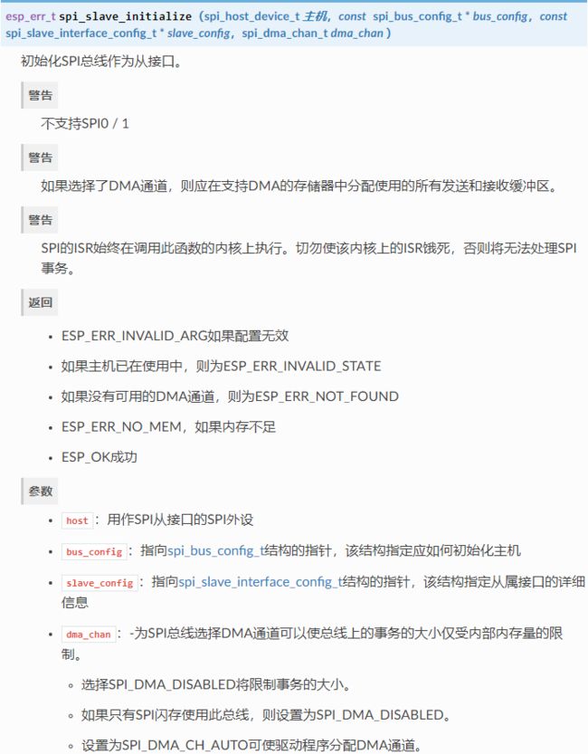
2.1 spi_slave_initialize

ESP32学习笔记(20)——SPI(从机)接口使用_第1张图片
注意:如果使用了DMA,需要保证使用pvPortMallocCaps(size, MALLOC_CAP_DMA)为缓冲区开辟内存,这样可以保障DMA能够访问到这些缓冲区

2.2 spi_slave_free

ESP32学习笔记(20)——SPI(从机)接口使用_第2张图片

2.3 spi_slave_queue_trans

ESP32学习笔记(20)——SPI(从机)接口使用_第3张图片

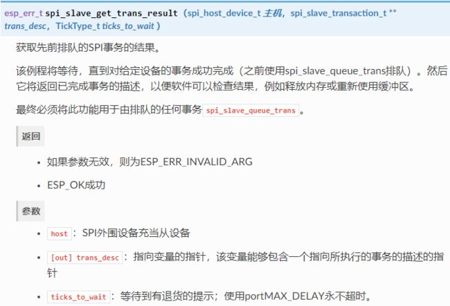
2.4 spi_slave_get_trans_result

ESP32学习笔记(20)——SPI(从机)接口使用_第4张图片

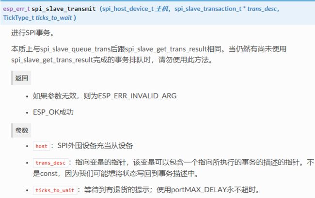
2.5 spi_slave_transmit

ESP32学习笔记(20)——SPI(从机)接口使用_第5张图片

三、编程流程

3.1 设置通信参数

通过调用函数初始化SPI总线spi_slave_initialize()。确保在struct中设置正确的I / O引脚bus_config。将不需要的信号设置为-1

如果传输长于32个字节,则通过将参数分别设置dma_chan1或来允许DMA通道1或2。否则,设置dma_chan0

3.2 运行SPI通信

在启动传输之前,请spi_slave_transaction_t使用所需的通信参数填充一个或多个结构。通过调用该函数将所有传输排队spi_slave_queue_trans(),然后在以后使用该函数查询结果spi_slave_get_trans_result(),或者通过将所有请求馈入来单独处理所有请求spi_slave_transmit()。后两个功能将被阻塞,直到主机启动并完成传输,从而导致发送和接收的数据排队。

(可选)要卸载SPI从驱动程序,请调用spi_slave_free()

四、SPI从机接收代码

使用 esp-idf\examples\peripherals\spi_slave\receiver 中的例程

/* SPI Slave example, receiver (uses SPI Slave driver to communicate with sender)

   This example code is in the Public Domain (or CC0 licensed, at your option.)

   Unless required by applicable law or agreed to in writing, this
   software is distributed on an "AS IS" BASIS, WITHOUT WARRANTIES OR
   CONDITIONS OF ANY KIND, either express or implied.
*/
#include 
#include 
#include 
#include 

#include "freertos/FreeRTOS.h"
#include "freertos/task.h"
#include "freertos/semphr.h"
#include "freertos/queue.h"

#include "lwip/sockets.h"
#include "lwip/dns.h"
#include "lwip/netdb.h"
#include "lwip/igmp.h"

#include "esp_wifi.h"
#include "esp_system.h"
#include "esp_event.h"
#include "nvs_flash.h"
#include "soc/rtc_periph.h"
#include "driver/spi_slave.h"
#include "esp_log.h"
#include "esp_spi_flash.h"
#include "driver/gpio.h"


/*
SPI receiver (slave) example.

This example is supposed to work together with the SPI sender. It uses the standard SPI pins (MISO, MOSI, SCLK, CS) to
transmit data over in a full-duplex fashion, that is, while the master puts data on the MOSI pin, the slave puts its own
data on the MISO pin.

This example uses one extra pin: GPIO_HANDSHAKE is used as a handshake pin. After a transmission has been set up and we're
ready to send/receive data, this code uses a callback to set the handshake pin high. The sender will detect this and start
sending a transaction. As soon as the transaction is done, the line gets set low again.
*/

/*
Pins in use. The SPI Master can use the GPIO mux, so feel free to change these if needed.
*/
#define GPIO_HANDSHAKE 2
#define GPIO_MOSI 12
#define GPIO_MISO 13
#define GPIO_SCLK 15
#define GPIO_CS 14

#ifdef CONFIG_IDF_TARGET_ESP32
#define RCV_HOST    HSPI_HOST
#define DMA_CHAN    2

#elif defined CONFIG_IDF_TARGET_ESP32S2
#define RCV_HOST    SPI2_HOST
#define DMA_CHAN    RCV_HOST

#endif


//Called after a transaction is queued and ready for pickup by master. We use this to set the handshake line high.
void my_post_setup_cb(spi_slave_transaction_t *trans) {
     
    WRITE_PERI_REG(GPIO_OUT_W1TS_REG, (1<<GPIO_HANDSHAKE));
}

//Called after transaction is sent/received. We use this to set the handshake line low.
void my_post_trans_cb(spi_slave_transaction_t *trans) {
     
    WRITE_PERI_REG(GPIO_OUT_W1TC_REG, (1<<GPIO_HANDSHAKE));
}

//Main application
void app_main(void)
{
     
    int n=0;
    esp_err_t ret;

    //Configuration for the SPI bus
    spi_bus_config_t buscfg={
     
        .mosi_io_num=GPIO_MOSI,
        .miso_io_num=GPIO_MISO,
        .sclk_io_num=GPIO_SCLK,
        .quadwp_io_num = -1,
        .quadhd_io_num = -1,
    };

    //Configuration for the SPI slave interface
    spi_slave_interface_config_t slvcfg={
     
        .mode=0,
        .spics_io_num=GPIO_CS,
        .queue_size=3,
        .flags=0,
        .post_setup_cb=my_post_setup_cb,
        .post_trans_cb=my_post_trans_cb
    };

    //Configuration for the handshake line
    gpio_config_t io_conf={
     
        .intr_type=GPIO_INTR_DISABLE,
        .mode=GPIO_MODE_OUTPUT,
        .pin_bit_mask=(1<<GPIO_HANDSHAKE)
    };

    //Configure handshake line as output
    gpio_config(&io_conf);
    //Enable pull-ups on SPI lines so we don't detect rogue pulses when no master is connected.
    gpio_set_pull_mode(GPIO_MOSI, GPIO_PULLUP_ONLY);
    gpio_set_pull_mode(GPIO_SCLK, GPIO_PULLUP_ONLY);
    gpio_set_pull_mode(GPIO_CS, GPIO_PULLUP_ONLY);

    //Initialize SPI slave interface
    ret=spi_slave_initialize(RCV_HOST, &buscfg, &slvcfg, DMA_CHAN);
    assert(ret==ESP_OK);

    WORD_ALIGNED_ATTR char sendbuf[129]="";
    WORD_ALIGNED_ATTR char recvbuf[129]="";
    memset(recvbuf, 0, 33);
    spi_slave_transaction_t t;
    memset(&t, 0, sizeof(t));

    while(1) {
     
        //Clear receive buffer, set send buffer to something sane
        memset(recvbuf, 0xA5, 129);
        sprintf(sendbuf, "This is the receiver, sending data for transmission number %04d.", n);

        //Set up a transaction of 128 bytes to send/receive
        t.length=128*8;
        t.tx_buffer=sendbuf;
        t.rx_buffer=recvbuf;
        /* This call enables the SPI slave interface to send/receive to the sendbuf and recvbuf. The transaction is
        initialized by the SPI master, however, so it will not actually happen until the master starts a hardware transaction
        by pulling CS low and pulsing the clock etc. In this specific example, we use the handshake line, pulled up by the
        .post_setup_cb callback that is called as soon as a transaction is ready, to let the master know it is free to transfer
        data.
        */
        ret=spi_slave_transmit(RCV_HOST, &t, portMAX_DELAY);

        //spi_slave_transmit does not return until the master has done a transmission, so by here we have sent our data and
        //received data from the master. Print it.
        printf("Received: %s\n", recvbuf);
        n++;
    }
}

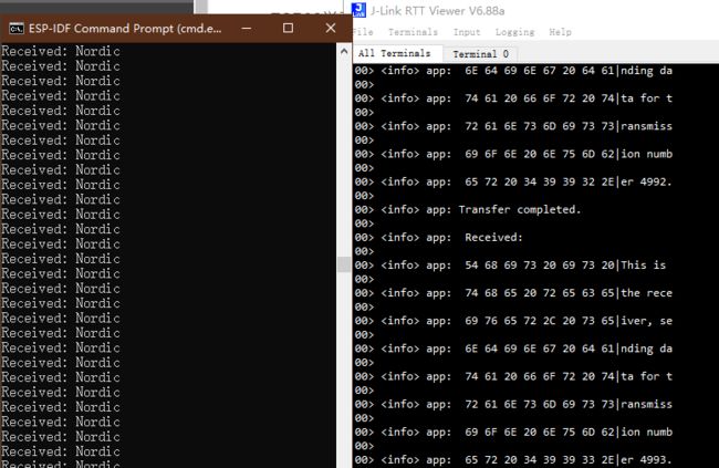
ESP32做从机,NRF52832做主机,查看打印:
ESP32学习笔记(20)——SPI(从机)接口使用_第6张图片


• 由 Leung 写于 2021 年 5 月 27 日

• 参考:ESPIDF开发ESP32学习笔记【SPI与片外FLASH基础】

你可能感兴趣的:(ESP32,ESP32,SPI,SPI从机,spi,slave)