- 模拟输入输出串口:读取一个模拟输入引脚,返回结果,然后用这个数据使LED灯变暗或者变亮
- 模拟输入:使用一个电压计来控制LED灯的闪烁
- 模拟写入Mega:使用Arduino Mega 开发板使12个LED灯一个接一个,逐渐变亮然后变暗
- 校准:对于超出模拟传感器范围的数值,定义一个最大值和最小值
- 渐变:用一个模拟输出引脚(PWM引脚)来使一个LED灯褪色。
- 使光滑:使多个模拟引脚的读取值变得顺滑
模拟输入输出串口
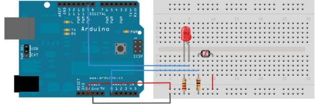
该例子展示怎么读取一个模拟输入引脚,并把结果按0-255的范围分配。用那个结果来设置一个输出引脚的脉冲宽度(PWM)来变暗或者变亮一个LED等,并打印这个值到Arduino IDE软件的串口监视器。
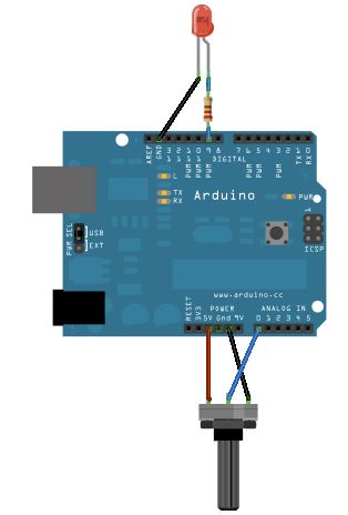
连接一个电位计的引脚到5V,中间的引脚到模拟引脚pin0,最后的引脚接地。然后串联一个LED灯()和一个220 ohm电流限制电阻到数字引脚pin9。LED灯的长,正极的引脚连接到电阻的输出端,而短,负极的引脚接地。
示例代码:
声明两个引脚的分配(电位计的模拟引脚pin0和LED的数字引脚pin9)和两个变量,传感值和输出值。你唯一要在setup()函数里做的就是开始串口通讯。
然后,在主循环里,传感值用来保存从电位计读取的未处理的模拟值。Arduino的模拟读取范围是0到1023,而模拟写入范围是0到255,因此从电位计出来的数据需要在使LED灯变暗之前转化成小范围的对应值。
为了转化这个值,使用一个叫map()的函数:
outputValue = map(sensorValue, 0, 1023, 0, 255);
输出值用来匹配从电位计出来的换算值。map()包括5个argument:映射值,输入的最低最高值,映射的最低最高值。在这种情况下,传感数据从它的0-1023初始范围映射到0-225范围。
最新的映射后的传感数据输出到模拟输出引脚来使LED变亮或变暗,就好像电位计在调节那样。最后未处理值和已换算值都发送到Arduino IDE软件的串口监视窗口里。
// These constants won't change. They're used to give names to the pins used:
const int analogInPin = A0;  // Analog input pin that the potentiometer is attached to
const int analogOutPin = 9; // Analog output pin that the LED is attached to

int sensorValue = 0;        // value read from the pot
int outputValue = 0;        // value output to the PWM (analog out)

void setup() {
  // initialize serial communications at 9600 bps:
  Serial.begin(9600);
}

void loop() {
  // read the analog in value:
  sensorValue = analogRead(analogInPin);
  // map it to the range of the analog out:
  outputValue = map(sensorValue, 0, 1023, 0, 255);
  // change the analog out value:
  analogWrite(analogOutPin, outputValue);

  // print the results to the Serial Monitor:
  Serial.print("sensor = ");
  Serial.print(sensorValue);
  Serial.print("\t output = ");
  Serial.println(outputValue);

  // wait 2 milliseconds before the next loop for the analog-to-digital
  // converter to settle after the last reading:
  delay(2);
}
模拟输入
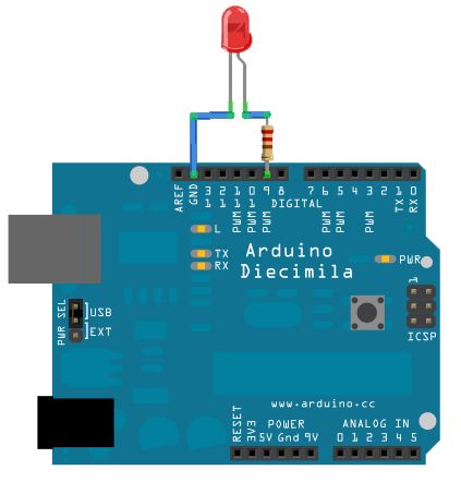
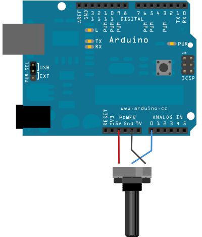
在这个例子里我们用一个变化电阻(一个电位计或者光敏电阻),我们通过Arduino或者Genuino开发板的一个模拟输入引脚读取它的值,并且根据这个值改变内置LED灯闪烁的速率。这个电阻的模拟值是作为电压读取,因为这是模拟输入的工作方式。
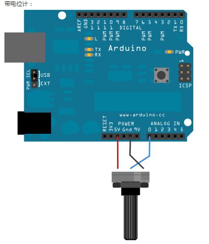
连接三根线到开发板。第一根从地到电位计的一个引脚。第二根从5V到电位计的另一个引脚。第三跟从模拟输入引脚A0到电位计的中间引脚。
这个例子里,可以使用开发板的连接到pin13的内置LED灯。如果用外加的LED灯,把它的长脚(正极或者阳极)串联一个220 ohm电阻,再连接到数字引脚pin13,而它的短脚(负极或者阴极)连接到pin13旁边的GND引脚(地)
这个电路基于光敏电阻,用一个分压器来使高阻抗模拟输入引脚来测量电压值。这些输入引脚不吸取任何电流,因而根据欧姆定律,这些在电阻的一端连接到5V的被测量的电压等于5V,而不管这些电阻值。为了获得按光敏电阻值匹配的电压值,一个电阻分压器是很有必要的。这个电路用一个可变电阻器,一个固定电阻,而测量点是在这些电阻值的中间。测量的电压(VOUT)符合以下公式:
Vout=Vin*(R2/(R1+R2))
其中Vin为5V,R2为10kohm和R1为光敏电阻值(范围从在黑暗的1M ohm到在亮处(10lumen)的10k ohm,再到光亮处(>100lumen)的1k ohm)。
示例代码
在程序开始部分,变量感应引脚被设置为模拟引脚A0,那个地方连接着电位计。ledPin被设置为数字引脚pin13.你也可以创建另外的变量,sensorValue来保存从你传感器里读到的值。
用 analogRead() 命令转化输入电压范围(0-5V)到数字值(0-1023)。这个可以用叫模拟数字转换器或者ADC的微控制器来实现。
通过转动电位计的轴,你可以改变电位计的电阻值。这会改变在中间引脚和其他两个外接引脚之间的电阻值,在模拟输入引脚处产生一个电压差。当轴转向一个方向,中间引脚和地引脚没有阻抗。中间引脚的电压值为0V,并且analogRead()返回0.当轴转向另一个方向,中间引脚和5V引脚没有阻抗。中间引脚的电压值为5V,并且analogRead()返回1023。转轴在之间时,analogRead()返回0-1023之间的一个数。
这个值,保存到sensorValue,用来为你的闪烁周期设置 delay() 。这个值越高,周期越长;越低,周期越短。在周期循环之前读取这个值,因此每次开/关的时间总是一样的。
int sensorPin = A0;    // select the input pin for the potentiometer
int ledPin = 13;      // select the pin for the LED
int sensorValue = 0;  // variable to store the value coming from the sensor

void setup() {
  // declare the ledPin as an OUTPUT:
  pinMode(ledPin, OUTPUT);
}

void loop() {
  // read the value from the sensor:
  sensorValue = analogRead(sensorPin);
  // turn the ledPin on
  digitalWrite(ledPin, HIGH);
  // stop the program for  milliseconds:
  delay(sensorValue);
  // turn the ledPin off:
  digitalWrite(ledPin, LOW);
  // stop the program for for  milliseconds:
  delay(sensorValue);
}
模拟写入Mega
这个例子利用板上的数字引脚的PWM数目优势,使在Arduino或者Genuino Mega开发板上的12个LED灯一个接一个变暗和变亮。
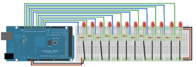
把12个LED灯的长脚(正极或者阳极)通过220 ohm限流电阻连接到数字引脚pin2-13。连接短腿(负极或阴极)到地。
代码示例:
在以下程序的setup()函数里,for()循环用来分配Mega板上的数字引脚pin2-13的输出。
然后,在下面的loop()函数里,用上for()循环三重嵌套。
三个循环的第一个循环
for (int thisPin =lowestPin; thisPin <= highestPin; thisPin++)
LED灯从最低位到最高一个接一个地移动。在这个循环允许从一个引脚移到下一个前,两件事必须完成。第一件是你使特定的LED灯通过这些代码变亮:
for (int brightness = 0; brightness < 255; brightness++) {
    analogWrite(thisPin, brightness);
    delay(2);
}
伴随上面的每次循环,变量brightness增加到一点,然后这个值写入到主循环里被选中当前引脚。当引脚达到PWM值(255),进入到下面的循环:
for (int brightness = 255; brightness >= 0; brightness--) {
    analogWrite(thisPin, brightness);
    delay(2);
}
这个循环使brightness变量每次减去一点,使LED灯逐渐变暗直至0。一旦达到0,就会进入主循环的for循环,并且程序会移动到下一个LED灯,重复上面的步骤。
// constants won't change. They're used here to set pin numbers:
const int buttonPin = 2;    // the number of the pushbutton pin
const int ledPin = 13;      // the number of the LED pin

// Variables will change:
int ledState = HIGH;         // the current state of the output pin
int buttonState;             // the current reading from the input pin
int lastButtonState = LOW;   // the previous reading from the input pin

// the following variables are unsigned longs because the time, measured in
// milliseconds, will quickly become a bigger number than can be stored in an int.
unsigned long lastDebounceTime = 0;  // the last time the output pin was toggled
unsigned long debounceDelay = 50;    // the debounce time; increase if the output flickers

void setup() {
  pinMode(buttonPin, INPUT);
  pinMode(ledPin, OUTPUT);

  // set initial LED state
  digitalWrite(ledPin, ledState);
}

void loop() {
  // read the state of the switch into a local variable:
  int reading = digitalRead(buttonPin);

  // check to see if you just pressed the button
  // (i.e. the input went from LOW to HIGH), and you've waited long enough
  // since the last press to ignore any noise:

  // If the switch changed, due to noise or pressing:
  if (reading != lastButtonState) {
    // reset the debouncing timer
    lastDebounceTime = millis();
  }

  if ((millis() - lastDebounceTime) > debounceDelay) {
    // whatever the reading is at, it's been there for longer than the debounce
    // delay, so take it as the actual current state:

    // if the button state has changed:
    if (reading != buttonState) {
      buttonState = reading;

      // only toggle the LED if the new button state is HIGH
      if (buttonState == HIGH) {
        ledState = !ledState;
      }
    }
  }

  // set the LED:
  digitalWrite(ledPin, ledState);

  // save the reading. Next time through the loop, it'll be the lastButtonState:
  lastButtonState = reading;
}
校准
这个例子展示一种矫正传感输入的技巧。这个开发板在启动时让传感器读取5秒钟,记录最高和最低值的轨迹。这些在程序里执行5秒的传感读取数定义为循环下一次读取的期望值的最小值和最大值。
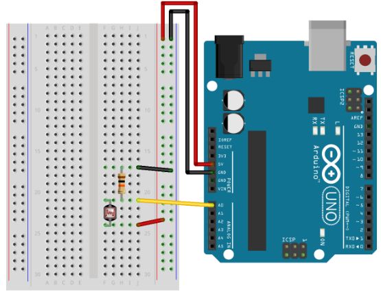
模拟传感器(如电位计,光传感器)在模拟输入A2上。LED在数字引脚pin9上。
把一个LED灯通过220 ohm限流电阻连接到数字引脚pin9。把一个光敏电阻的一端连接到5V。另一端连接到pin0,并通过10k ohm电阻下拉到地。
示例代码:
在启动函数前,你要为最大值和最小值设置初始值,如:
int sensorMin = 1023;        // minimum sensor value
int sensorMax = 0;           // maximum sensor value
这些可能看起来反了。开始时,你设置最大的高电平,然后读取任何比它低的值,将它作为新的最小值保存。同样地,你设置最小的低电平,然后读取任何比它高的值,将它作为新的最大值保存。就像这样:
 // calibrate during the first five seconds
 while (millis() < 5000) {
   sensorValue = analogRead(sensorPin);

   // record the maximum sensor value
   if (sensorValue > sensorMax) {
     sensorMax = sensorValue;
   }

   // record the minimum sensor value
   if (sensorValue < sensorMin) {
     sensorMin = sensorValue;
   }
 }
这种方式下,你做的更多读取可能会根据这个最大值和最小值按比例分配。就像这样:
// apply the calibration to the sensor reading
sensorValue = map(sensorValue, sensorMin, sensorMax, 0, 255);
全部代码:
// These constants won't change:
const int sensorPin = A0;    // pin that the sensor is attached to
const int ledPin = 9;        // pin that the LED is attached to

// variables:
int sensorValue = 0;         // the sensor value
int sensorMin = 1023;        // minimum sensor value
int sensorMax = 0;           // maximum sensor value


void setup() {
  // turn on LED to signal the start of the calibration period:
  pinMode(13, OUTPUT);
  digitalWrite(13, HIGH);

  // calibrate during the first five seconds
  while (millis() < 5000) {
    sensorValue = analogRead(sensorPin);

    // record the maximum sensor value
    if (sensorValue > sensorMax) {
      sensorMax = sensorValue;
    }

    // record the minimum sensor value
    if (sensorValue < sensorMin) {
      sensorMin = sensorValue;
    }
  }

  // signal the end of the calibration period
  digitalWrite(13, LOW);
}

void loop() {
  // read the sensor:
  sensorValue = analogRead(sensorPin);

  // apply the calibration to the sensor reading
  sensorValue = map(sensorValue, sensorMin, sensorMax, 0, 255);

  // in case the sensor value is outside the range seen during calibration
  sensorValue = constrain(sensorValue, 0, 255);

  // fade the LED using the calibrated value:
  analogWrite(ledPin, sensorValue);
}
渐变
这个例子示范了怎样用模拟输出(PWM)来使LED灯变亮或者变暗。PWM是一种技巧,可以使数字引脚通过快速开关和不同的开关时间来表现出一种类似模拟的动作。
一个LED灯通过一个220 ohm电阻连接到数字引脚pin9
示例代码:
在这个例子里,两个循环一个接一个地执行来增加然后减少pin9的输出值
int ledPin = 9;    // LED connected to digital pin 9

void setup() {
  // nothing happens in setup
}

void loop() {
  // fade in from min to max in increments of 5 points:
  for (int fadeValue = 0 ; fadeValue <= 255; fadeValue += 5) {
    // sets the value (range from 0 to 255):
    analogWrite(ledPin, fadeValue);
    // wait for 30 milliseconds to see the dimming effect
    delay(30);
  }

  // fade out from max to min in increments of 5 points:
  for (int fadeValue = 255 ; fadeValue >= 0; fadeValue -= 5) {
    // sets the value (range from 0 to 255):
    analogWrite(ledPin, fadeValue);
    // wait for 30 milliseconds to see the dimming effect
    delay(30);
  }
}
使光滑
该程序重复读取一个模拟输入,分析一个运行均值,并且打印到电脑。这个例子用在你想使跳动的不规则的传感值变得光滑的时候,示范了怎么用保存数组。
把电位计的一个引脚连接到5V,中间引脚连接到模拟引脚A0,最后的引脚连接到地。
示例代码:
下面的代码顺序保存10个模拟引脚的读取值,一个接一个放进一个数组里。每一次有新的值,把所有值加起来,然后取平均值,把这个平均值用作顺滑输出的数据。因为这种平均每次加一个新的值到数组里(好过一次等够10个新值),分析运行的均值之间并没有滞后时间。
改变数组的大小,通过改变 numReadings 为一个更大的值将会使保存数据变得比之前光滑。
// Define the number of samples to keep track of. The higher the number, the
// more the readings will be smoothed, but the slower the output will respond to
// the input. Using a constant rather than a normal variable lets us use this
// value to determine the size of the readings array.
const int numReadings = 10;

int readings[numReadings];      // the readings from the analog input
int readIndex = 0;              // the index of the current reading
int total = 0;                  // the running total
int average = 0;                // the average

int inputPin = A0;

void setup() {
  // initialize serial communication with computer:
  Serial.begin(9600);
  // initialize all the readings to 0:
  for (int thisReading = 0; thisReading < numReadings; thisReading++) {
    readings[thisReading] = 0;
  }
}

void loop() {
  // subtract the last reading:
  total = total - readings[readIndex];
  // read from the sensor:
  readings[readIndex] = analogRead(inputPin);
  // add the reading to the total:
  total = total + readings[readIndex];
  // advance to the next position in the array:
  readIndex = readIndex + 1;

  // if we're at the end of the array...
  if (readIndex >= numReadings) {
    // ...wrap around to the beginning:
    readIndex = 0;
  }

  // calculate the average:
  average = total / numReadings;
  // send it to the computer as ASCII digits
  Serial.println(average);
  delay(1);        // delay in between reads for stability
}